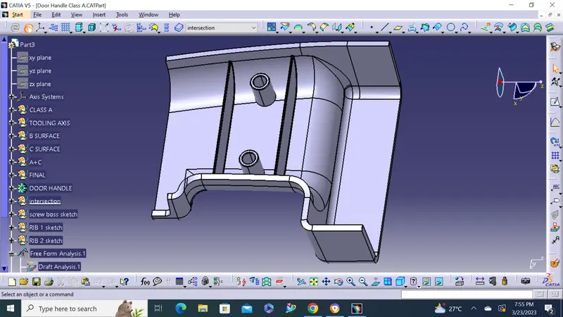
Week 10 - Challenge 1- Attachment Feature Creation (Ribs & Screw Boss)
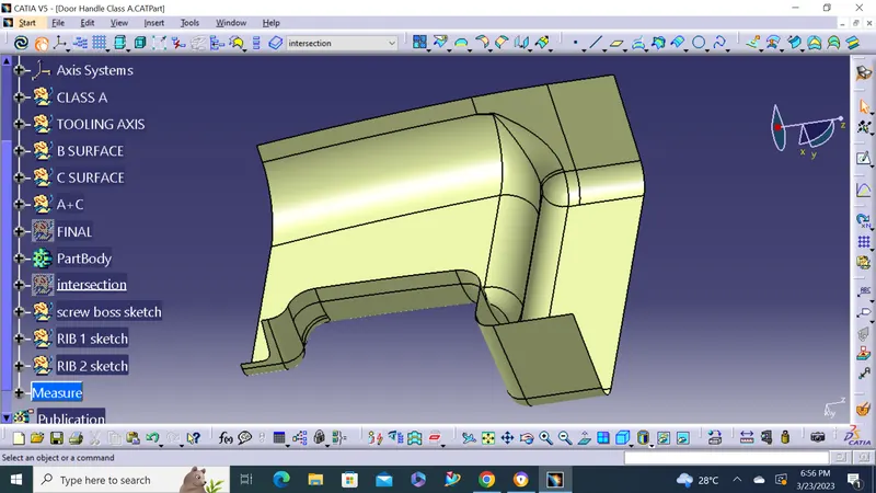
CLASS A SURFACE:
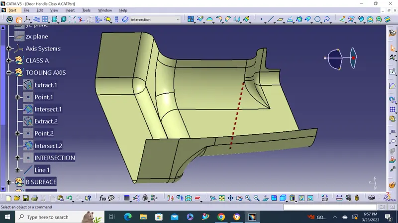
TOOLING AXIS:
- It is the direction in which the component will be ejecting after the molding process is completed.
- The direction of tooling axis should clear the maximum portion of the part.
- It should be selected in such way that number of side cores will be minimum as it will add more cost to the process.
- For this case as no hole is concerned, so we will try to consider the perpendicular axis of that dented curved surface, for creating the tooling axis.So we will analyse bothe perpendicular plane.
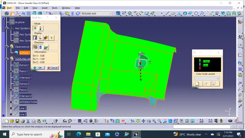
DRAFT ANALYSIS CLASS A SURFACE:
- The part created has to be changed to the material modes in the display frame.
- Compass is enabled aligned light along with the tooling direction.
- Lock command is then applied to fix compass along with tooling axis.
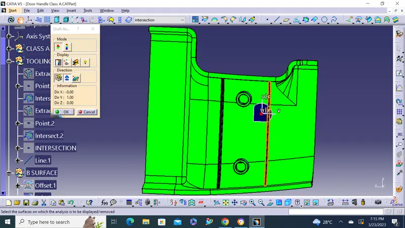
- Color codes are classified and Draft angle is applied.
- Running point analysis is used to display permissible draft and angles
CLASS B SURFACE:
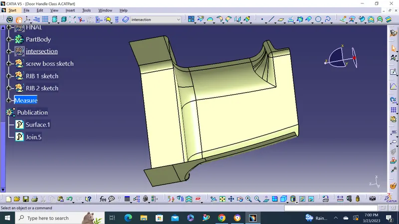
CLASS C SURFACE:
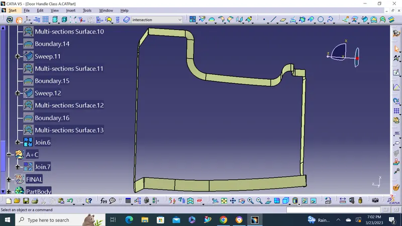
A+B+C SURFACE:
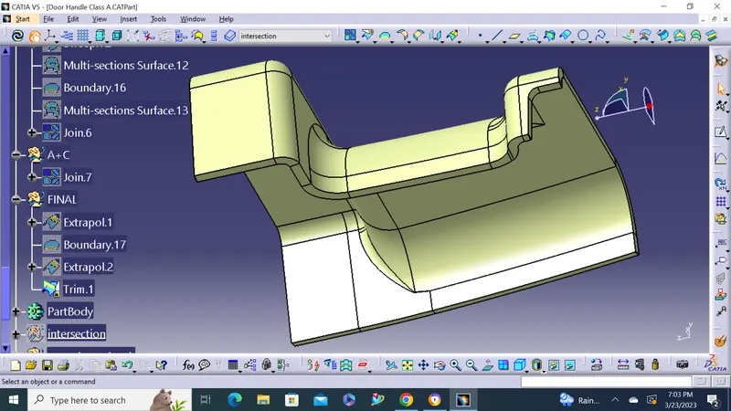
CLOSED SOLID SURFACE:
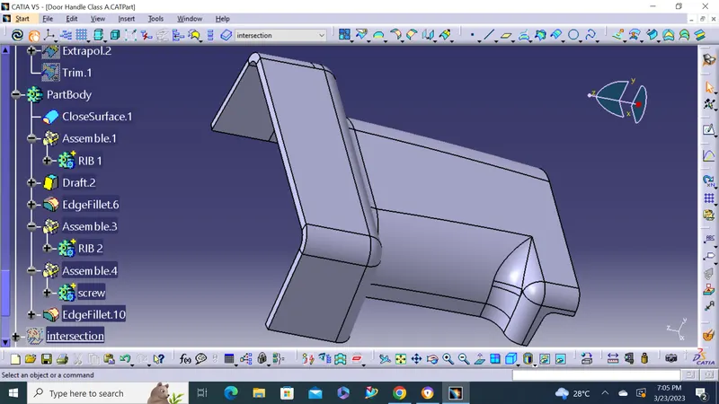
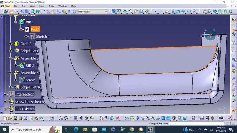
RIB 1:
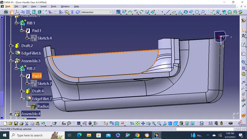
Design rules to follow while creating ribs
- Min draft: 0.5mm per side
- Rib thickness-: 0.4*t
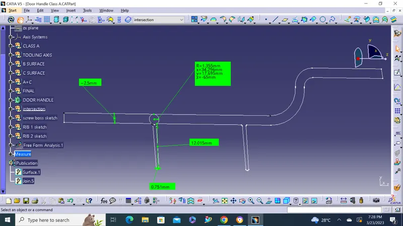
- Min thk on tip of rib: 0.75mm
- Max Rib fillet radius: 0.25mm
- Rib height: less than 5* nominal wall thickness
- Rib should be spaced with a height to width ratio: 3:1 or 2:1
RIB 2:
SCREW BOSS:
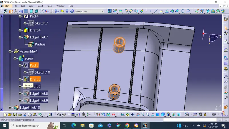
Screw Boss features are commonly found in injection molding designs. They are used to aid in the assembly of molded parts by providing a channel for a screw.
Their primary use is to strengthen holes or slots in the surface present in the part model.
Design rules consider while creating a screw boss
• Thickness
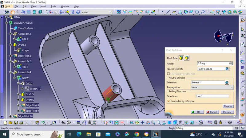
• Draft
• optional radii
• Boss gussets
•Type of ejection
The construction process of creating the screw boss is explained below:
For thickness, the design rule is as follows,
Thickness,w=0.6*T
=0.6*2.5
=1.5 mm
Therefore, the thickness of the boss can be 1.5 mm per side.
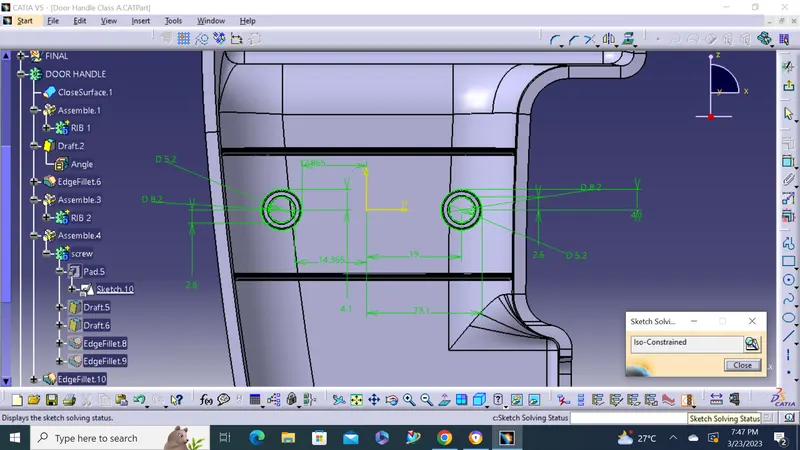
In this case, we have considered the size of the screw boss as M06.
DRAFT & SKETCH ISO_CONSTRAIN:
FINAL DRAFT ANALYSIS:
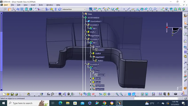
INTERSECTION:
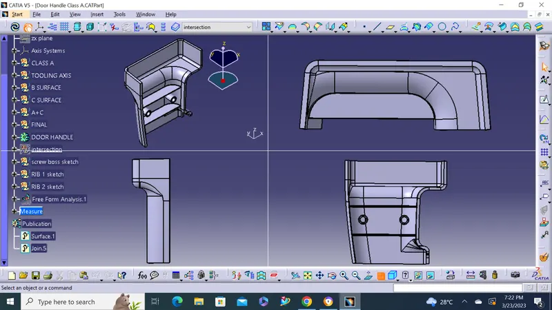
ISOMETRIC, FRONT, SIDE, AND TOP VIEW:
TREE STRUCTURE:
Challenge 1- Attachment Feature Creation (Ribs & Screw Boss)