Week 10 - Challenge 1- Attachment Feature Creation (Ribs & Screw Boss)
OBJECTIVE
To create the Rib and Screw Boss for the Door Handle part body in CATIA considering the design rules and dimensions. Also perform draft analysis for the model.
DESIGN METHODOLOGY
Door Handle
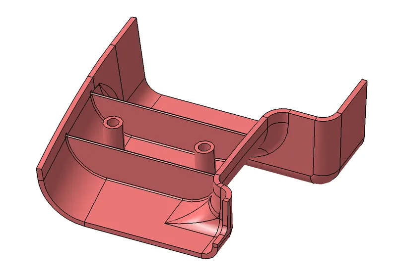
From the given Class A Surface of Door Handle is supposed to create Class B Surface, Class C Surface and Final part model for the Door Handle. Create Tooling axis from Class A Surface using bisecting line method.
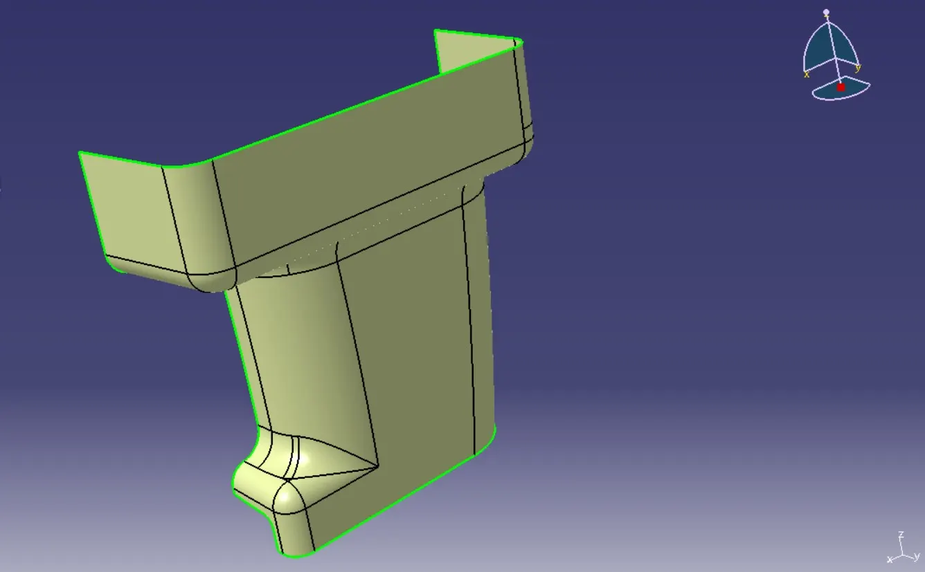
Commands Used to create Class A Surface, Class B Surface, Class C Surface and Final Surface in Generative shape design, CATIA are:
- Join
- Intersect
- Point
- Line
- Extract
- Surface Untrim
- Offset
- Extrapolate
- Boundary
- Split
- Trim
- Curve Smooth
- Sweep
- Edge Fillet
Class A Surface
Class A surface is the aesthetic part of the model, which is already created by design engineer as input Class A Surface. Class B Surface is then created by offsetting the Class A Surface according to the thickness of the part and both the surfaces require to clear draft analysis.
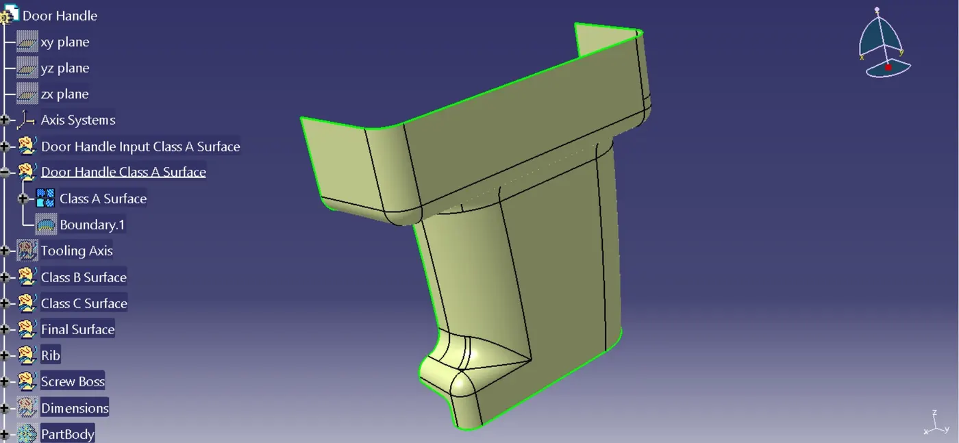
Tooling Axis
The Tooling Axis indicates the direction in which the mold separates from the casting. The mold is divided into two distinct sections: core and cavity. The Tooling Axis is created when the Core separates from the Cavity. The draft angle also determines the part's ejection from the mold. A zero draft may produce shrinkage, resulting in difficult or no ejection. As a result, for all plastic component manufacturability, the draft angle is set to 3 degrees.
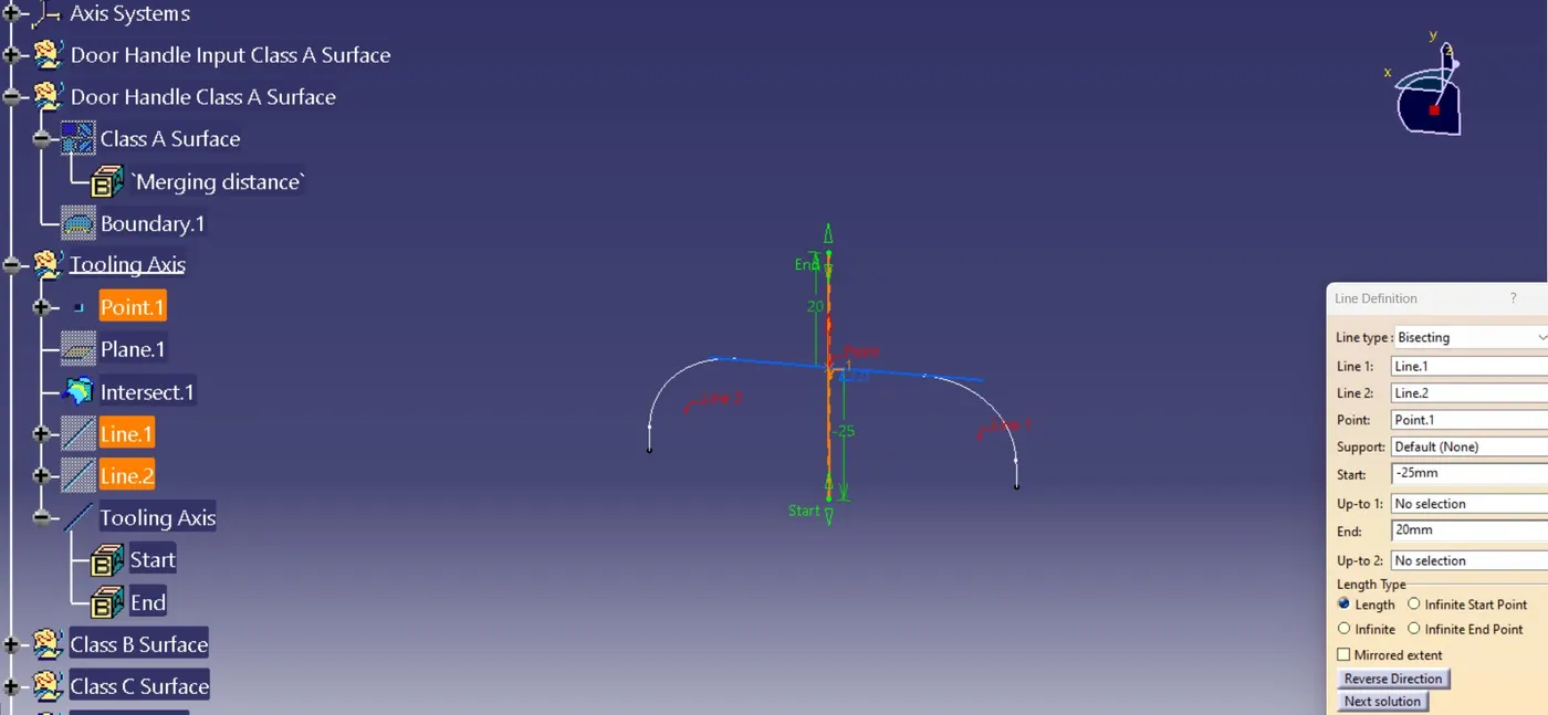
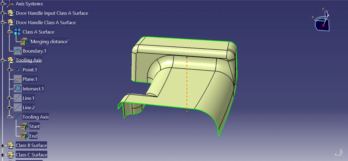
In most cases tooling direction could be along the surface, or by creating bisecting line from the surface profile. For door handle, the tooling direction is created using Bisecting Line method along with the boundary of door handle which itself clears the draft, allowing the component to be made.
Tooling axis of door handle:
Draft Analysis
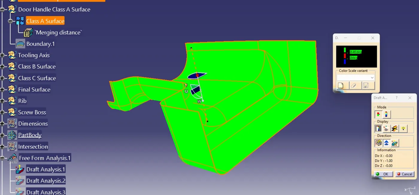
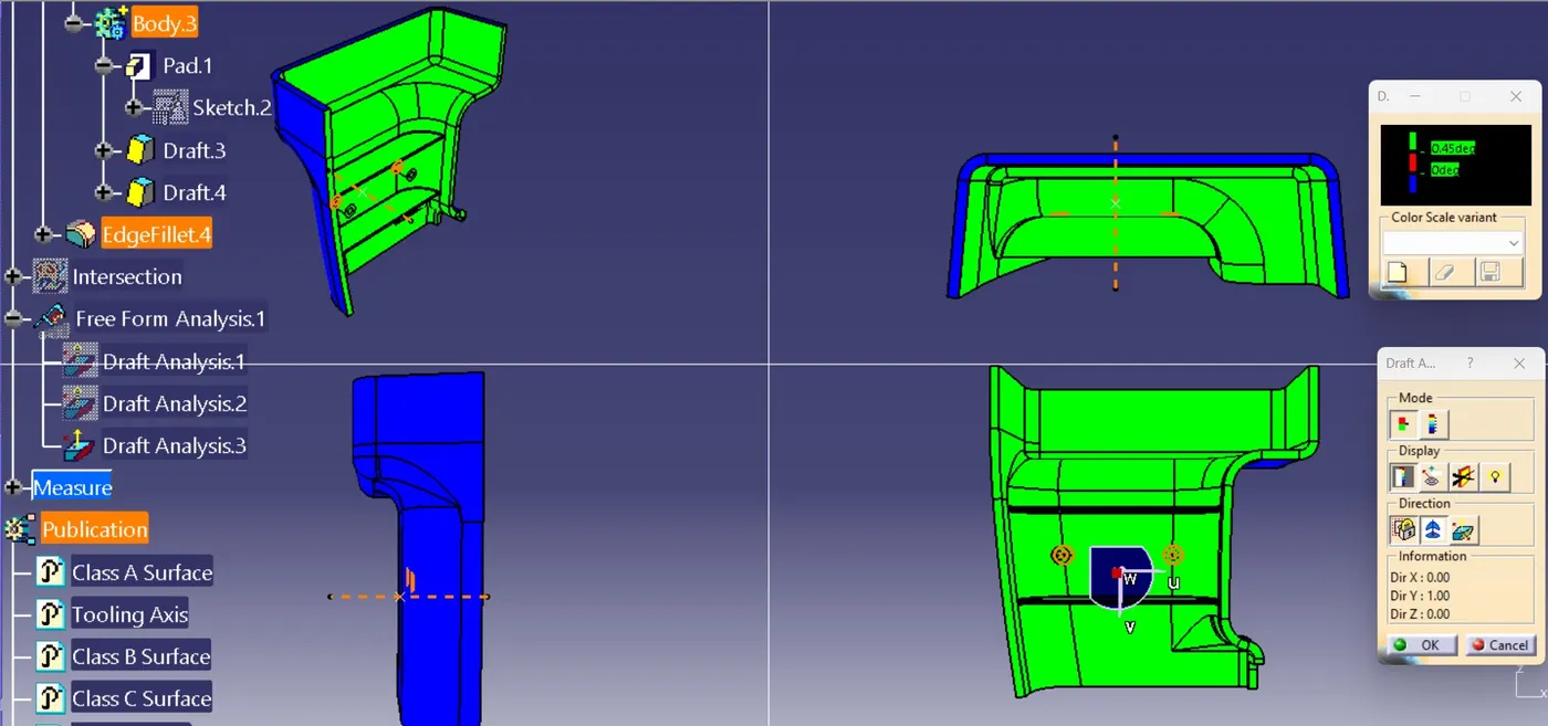
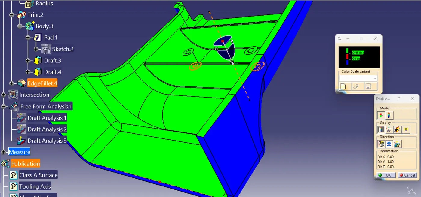
Choosing the class A surface perform Feature Draft Analysis with respect to Tooling Axis. Green colour indicates the surface can be manufactured using core and cavity method.
Class B Surface
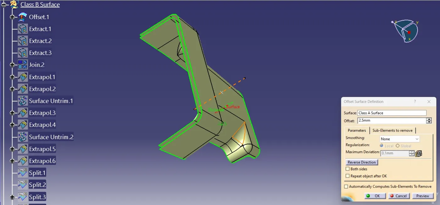
Class B Surface is created by offsetting the Class A Surface with thickness of 2.5mm.
Class C Surface
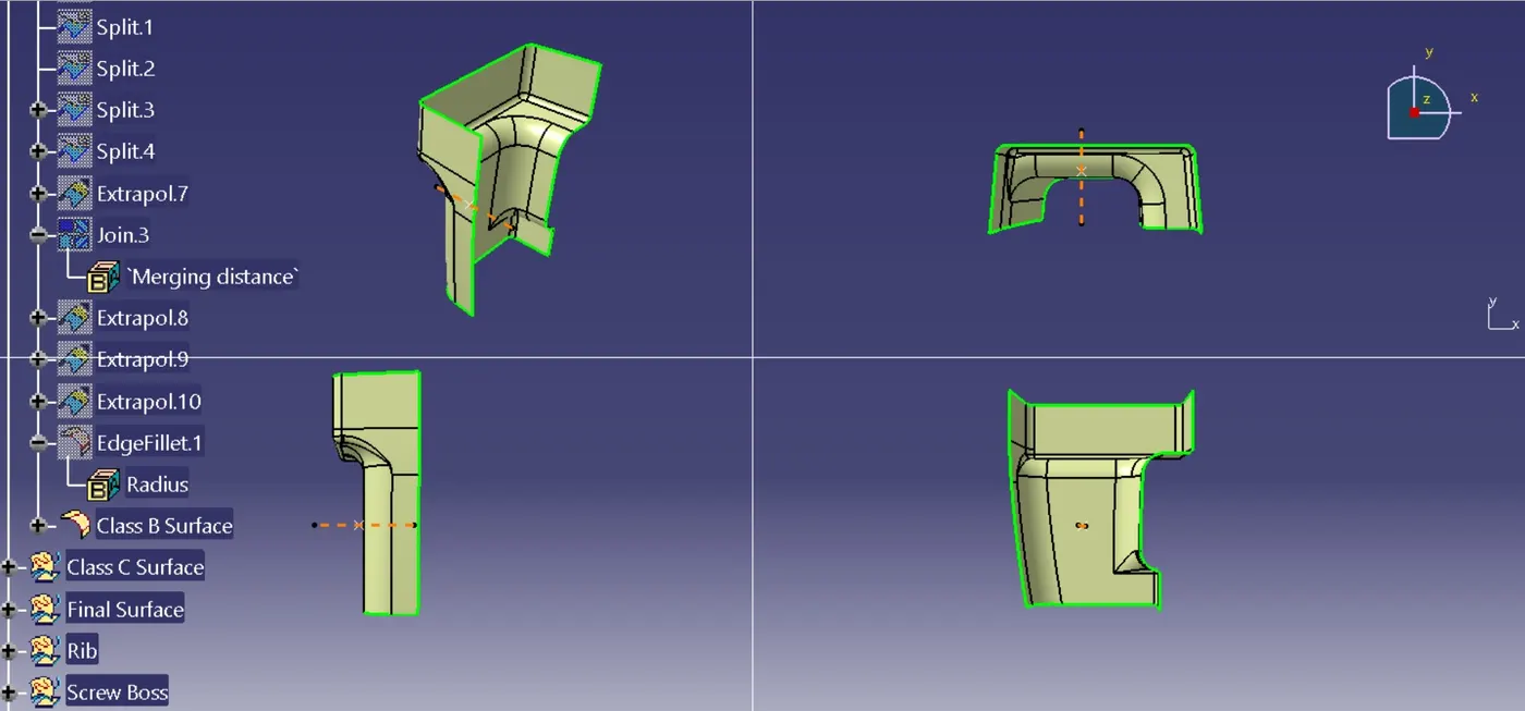
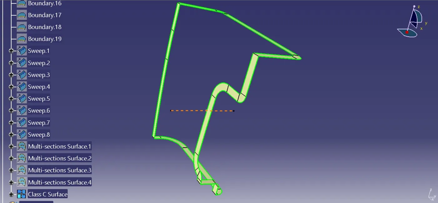
Class C Surface is the joining surface between Class A Surface and Class B Surface to obtain the solid plastic model. It is created using boundary command on Class A Surface and performing Sweep command with reference to Tooling Axis.
Final Surface
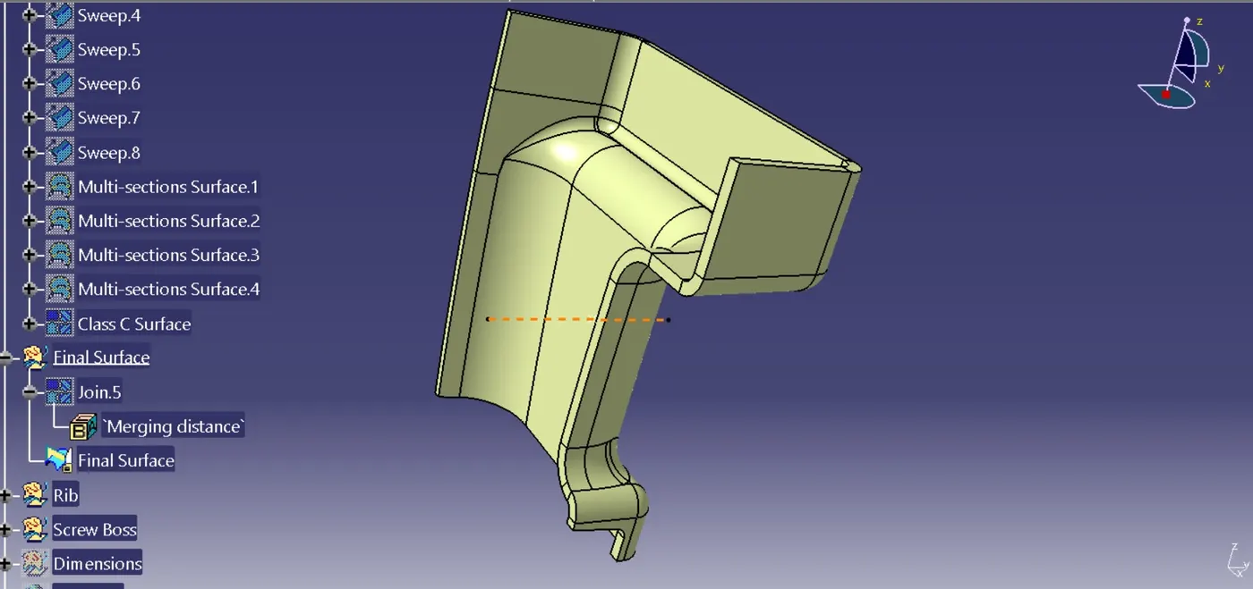
Final Surface is obtained by joining Class A Surface and Class C Surface, then using Trim command with the joined surface and Class B Surface to obtain the closed surface model.
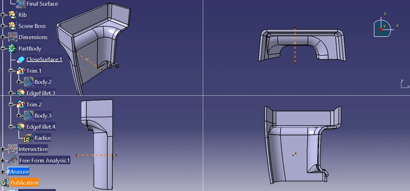
For the final door handle part model, plastic model can be obtained by going to Part Workbench and using command Close Surface.
Rib Design
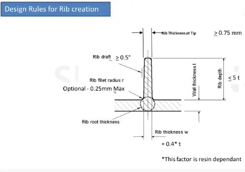
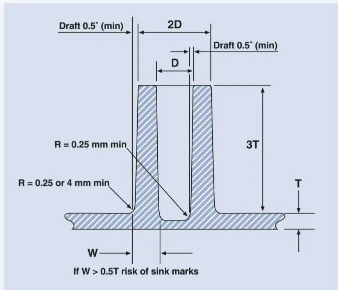
- Thickness of ribs 40% of wall thickness, here the wall thickness refers to the thickness of Door Handle
- Rib root thickness should not be more than 30% of wall thickness
- Height should be ≤ 5 times the wall thickness
- Draft: 0.5 Degree per side (minimum)
- Spacing between the ribs are supposed to be in the ratio of 3:1- steel height/width ratio (maximum).
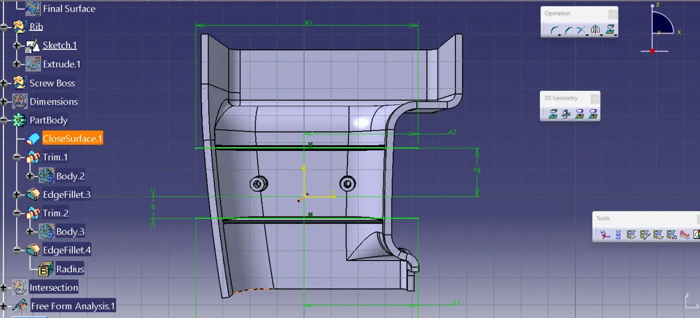
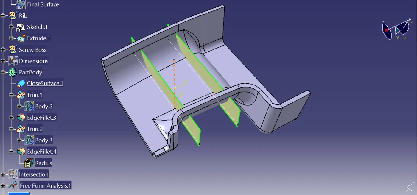
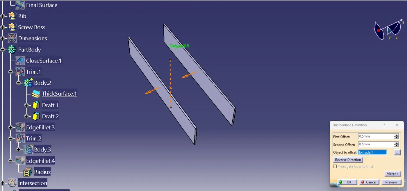
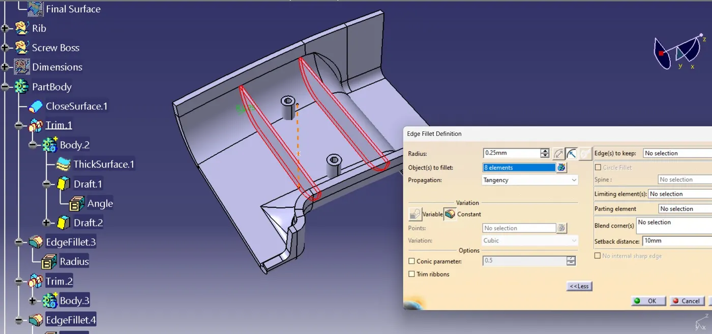
Using Sketch tool Rib length is created and then using Extrude command required rib height along the the part model surface is obtained. Thick Surface command is used for a 0.5mm to both both directions are given and thus obtaining Rib plastic model of 1mm thickness. Rib draft of 0.5 degrees are given and fillets are given to the rib of 0.25mm radii. Here for the door handle two Ribs are created.
Dimensions:
- Rib length = 5*2.5mm =11.489 mm
- Rib thickness = 0.4*2.5mm=1.0mm
- Rib fillet radii = 0.25mm
- Rib draft = 0.5deg
- Rib thickness at tip = 1.004mm
Screw Boss Design
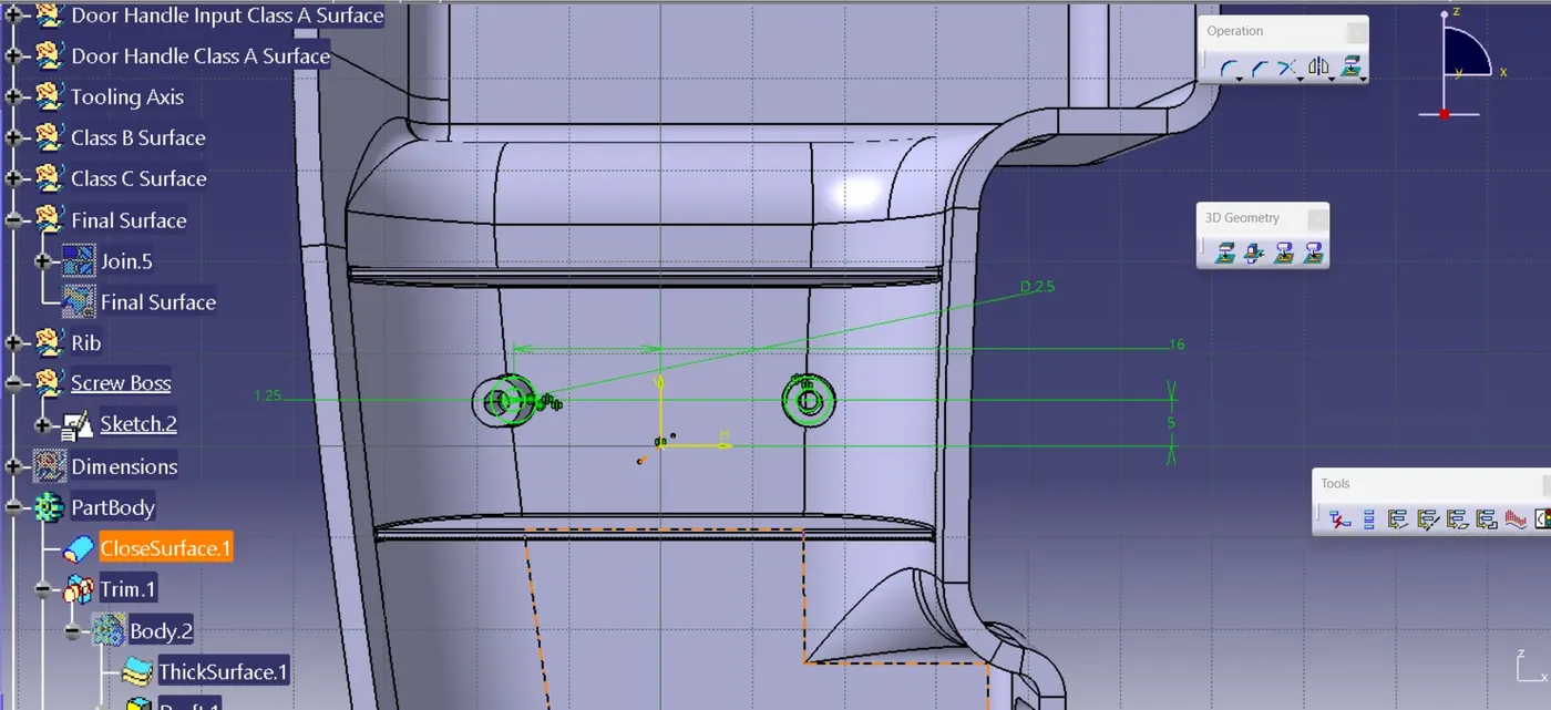
Sketch used for creating screw boss. Here two screw bosses are created.
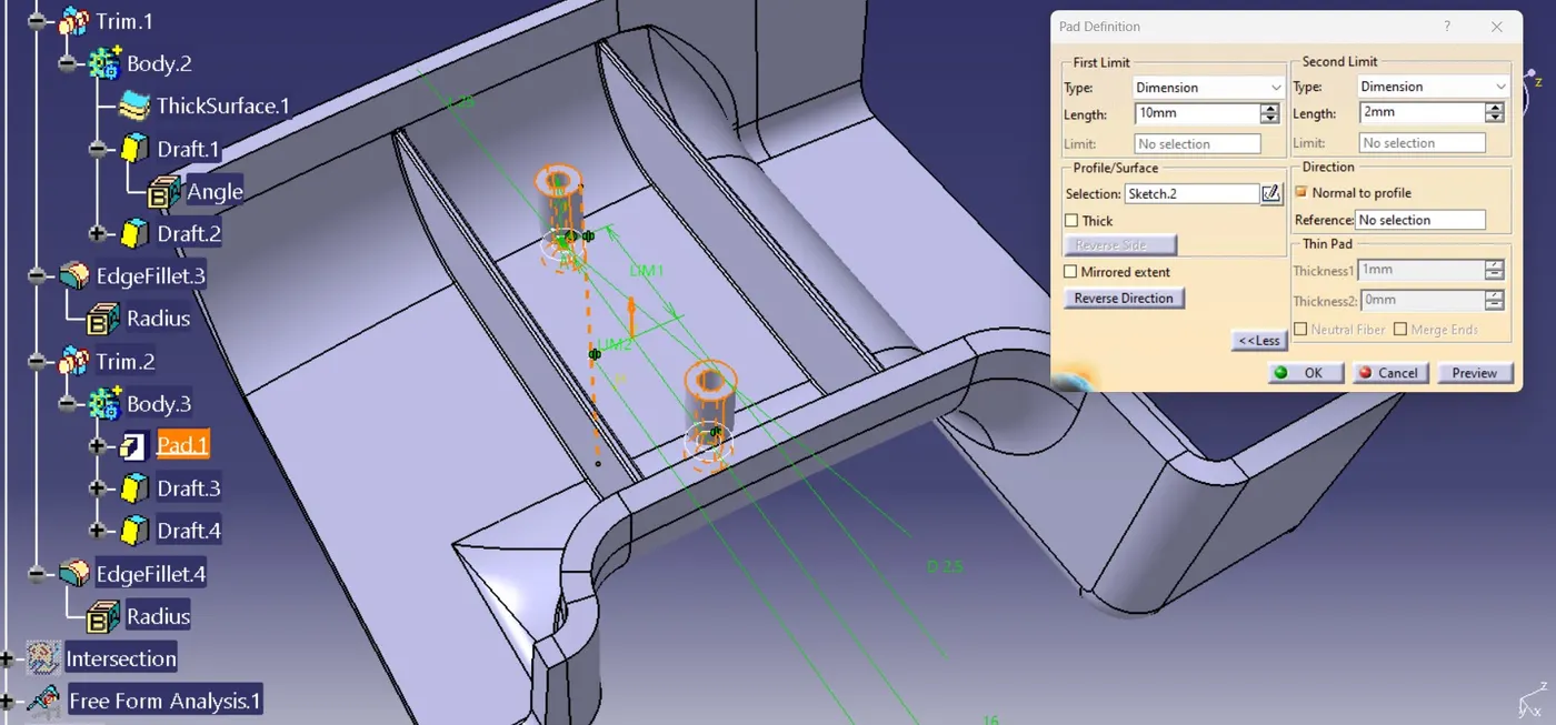
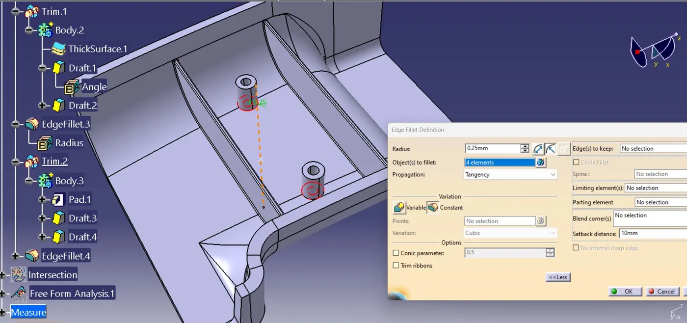
Intersection of door handle with rib and screw boss.
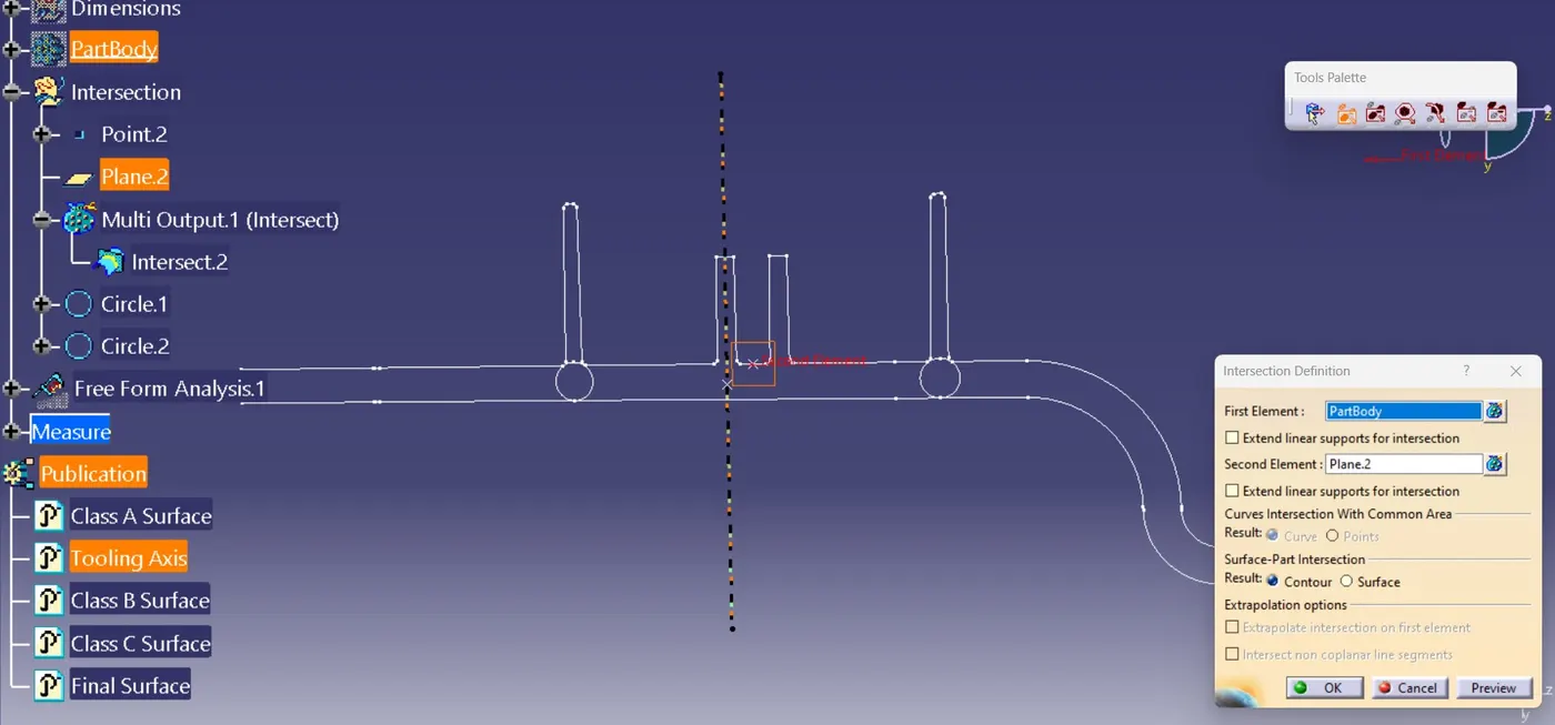
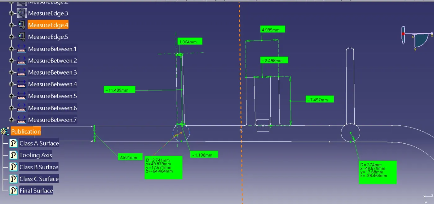
Door handle with attachment features: Ribs and Screw Bosses
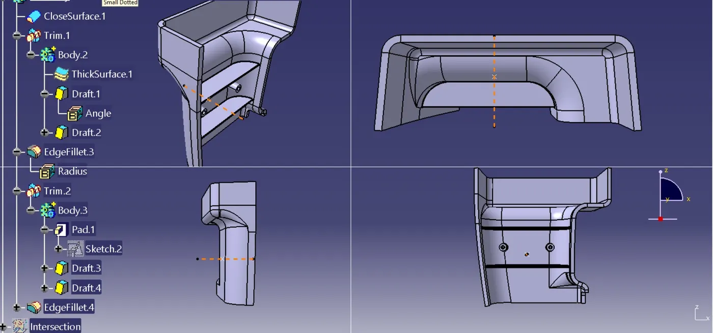
Draft analysis of Final Door Handle
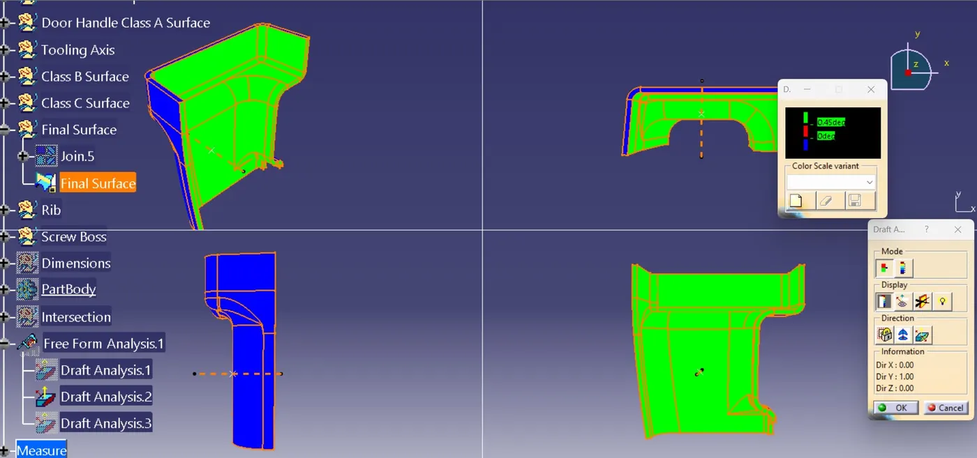
End draft analysis of Door Handle with attachment features
CONCLUSION
From the given input Class A Surface of door handle, the final door handle plastic model with attachment features : Ribs and Screw Bosses are created using CATIA. The draft analysis for door handle with ribs and screw bosses was performed and thus clearing the required draft angle. Publications for Class A Surface, Tooling Axis, Class B Surface, Class C Surface, Final surface of door handle was also created using Publication Tool.