Week 10 - Challenge 1- Attachment Feature Creation (Ribs & Screw Boss)
ATTACHMENT FEATURE CREATION (RIBS & SCREW BOSS)
AIM- Create the attachment features creation of ribs & screw boss on the door handle component by creating Class B & Class C surface with the help of given Class A surface & follow the design parameters.
GENERAL GUIDLINE OF ATTACHMENT FEATURE CREATION
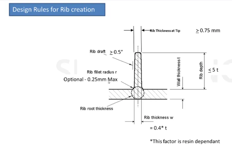
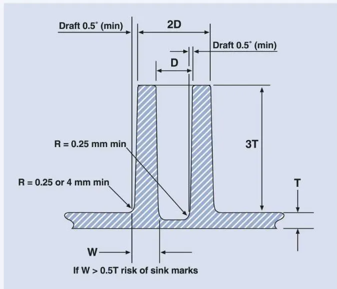
RIBS-
· Minimum thickness at rib tip = 0.75mm
· Optional rib fillet radius = 0.25mm
· Rib height <5 * nominal wall thickness
· W = 0.4*t
· Minimum draft angle per side = 0.5 degree
· Do not want to significantly increase rib thickness must not violate 40% * thickness requirement.
SCREW BOSS
· Minimum draft angle on the walls of boss = 0.5 degree
· Thickness- Typically 40%* of the nominal wall at the base
· Height to diameter ratio=3:1
· Radii-0.25mm maximum radii
INTRODUCTION
CLASS A SURFACE – The outermost skin of a part model which is visibly aesthetic surface/ free-form surface having an optimal shape & high surface quality. Design engineer with help of class A Surface create class B surface & class C surface.
CLASS B SURFACE- A surface below the Class A surface is created by design engineer to give a desirable thickness. This surface is also known as engineering surface.
CLASS C SURFACE- A surface that join Class A Surface & Class B surface.
DESIGN METHODOLOGY
· TOOLING AXIS CREATION
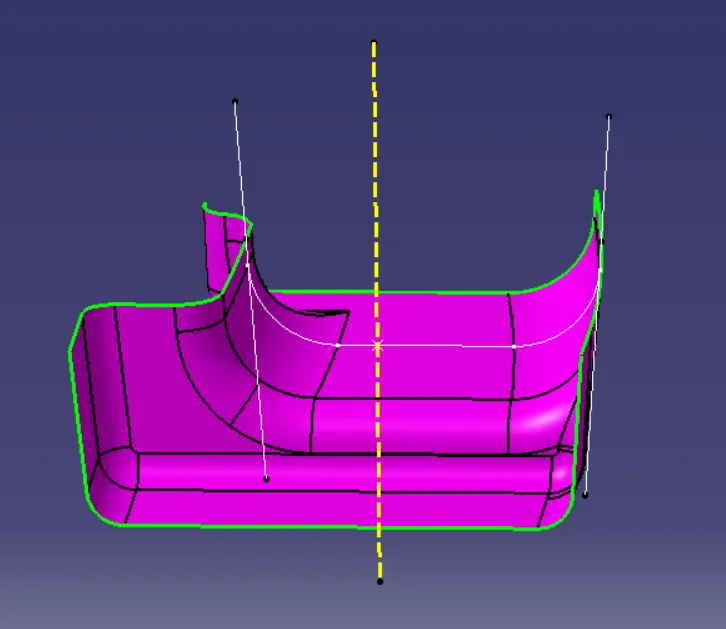
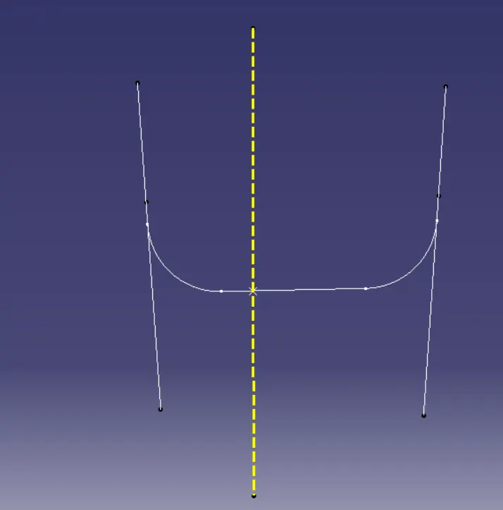
For creating tooling axis for the door handle component, we have to cross check the three directional axis X-Axis, Y-Axis & Z-Axis which suitable to manufacture the component. In this case, Z- axis direction is suitable to manufacture this door handle component. First step, is to extract the surface & create mid- point. Through intersect command, intersect the Class A surface on the component. Go to line command, create two lines from the intersect line. Again, go to line command, change the bisecting mode & select the two line. A bisecting line is generated is consider as tooling axis.
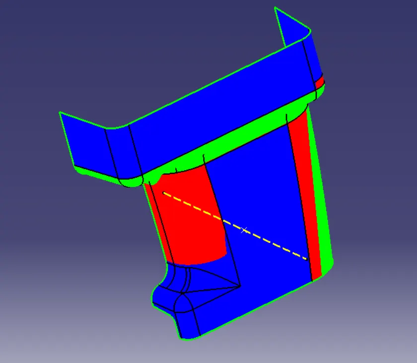
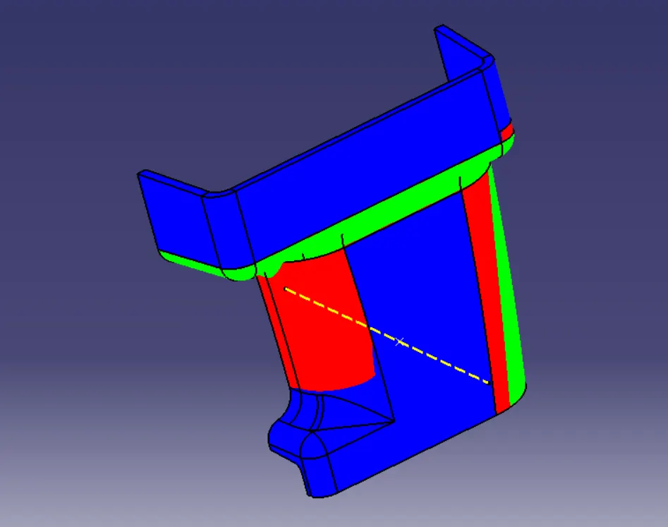
· DRAFT ANALYSIS- Draft analysis is a command which enable to detect the draft angle of the surface. This type of analysis is performed on the colour ranges to identify the zones on the analysis of the element with references to tooling axis.
Draft analysis on plastic material is checked with reference to tooling axis at minimum angle of 3 degree & showing green colour then it is safe.
· CLASS B SURFACE CREATION
First step of creating Class B surface is to offset the Class A surface to 2.5 mm inwards. Check for incomplete patches created in the offset Class B surface. In this case, multi-section surface, command is used to fill up the incomplete patch in the Class B surface. Later, through join command, join the offset surface & multi-section surface to create as single Class B surface.
· CLASS C SECTION
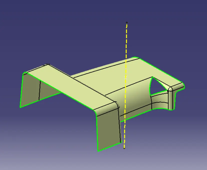
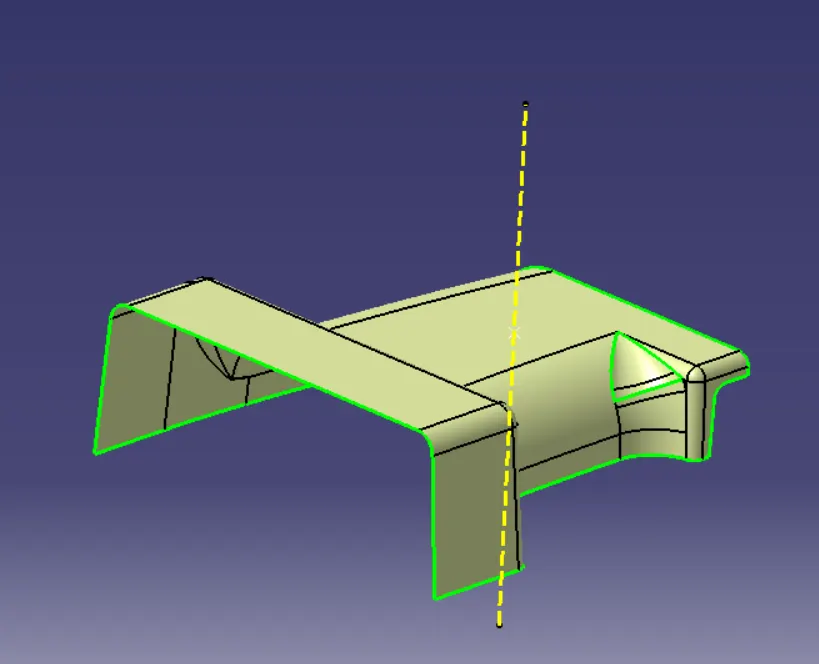
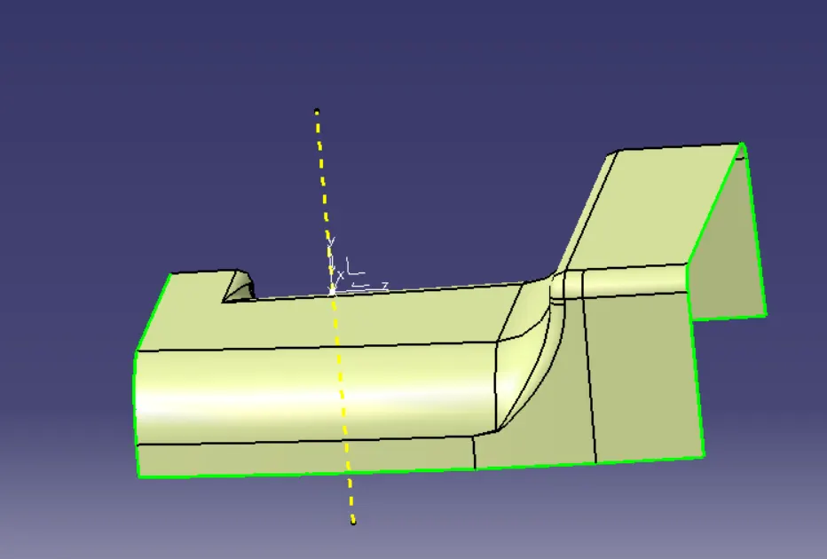
Take the boundary of the Class A surface to create the Class C surface. Go to sweep command, select with refence surface.
If the generated C surface is parallel to the tooling axis create the sweep along the draft direction at angle of 3 degree.
If the surface is perpendicular to the tooling axis, then create the sweep using the reference surface option then extrapolate the connecting surface & trim the surface together & join them all together to form the Class C surface.
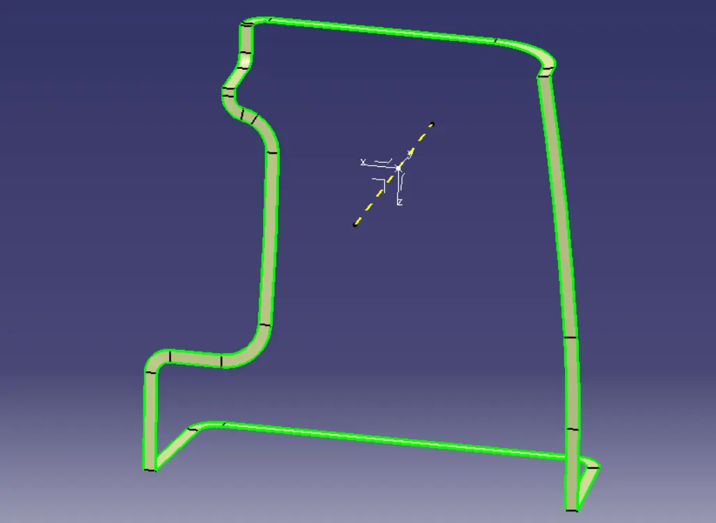
Now, join the class A surface with class C surface
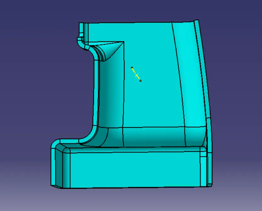
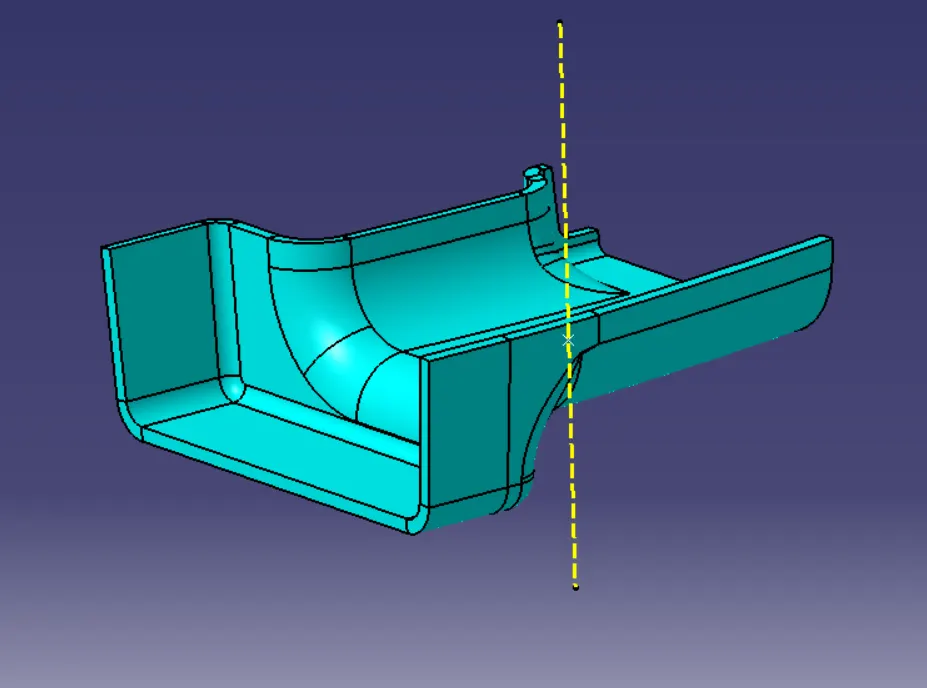
At last step, define to part body & switch to mechanical design mode to made the body solid part by going to closed surface.
Hence, the final surface is created.
RIB CREATION
· Extract the surface & create a plane.
· Select the plane for sketch & draw iso-constraint line.
· Extrude the line to height of
H= 5*2.5= 12.5mm
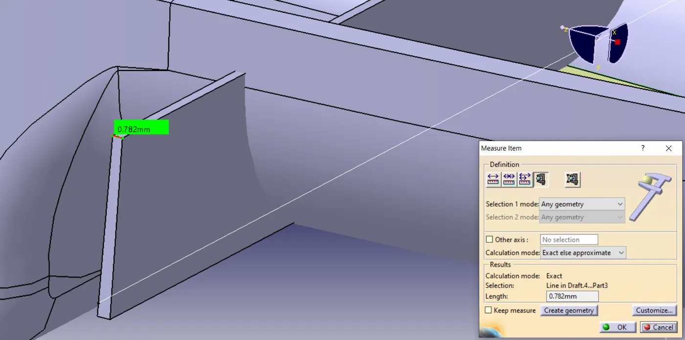
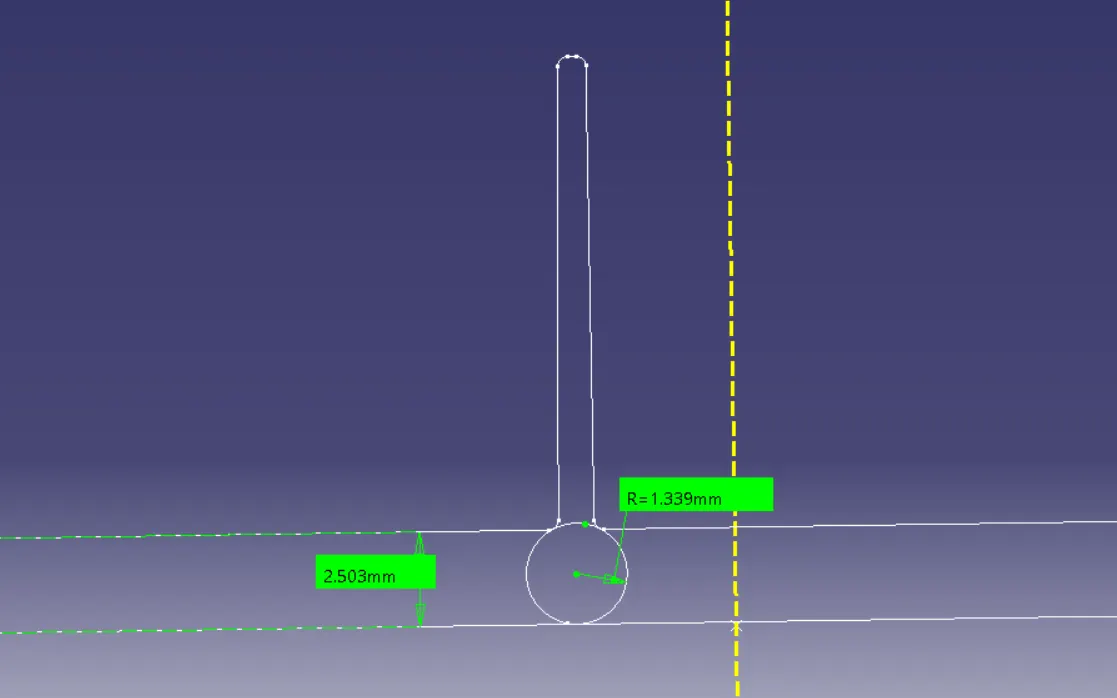
· Now thicken the extrude surface w= 0.4*2.5=1mm
· Now apply the draft to the surface as reference to the plane & the pulling direction as tooling axis to a draft angle of 0.5 degree on each side.
· Apply the fillets of 0.25mm on each side.
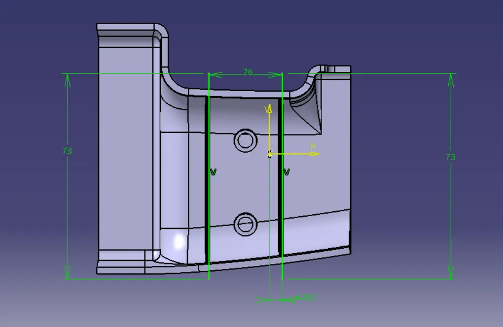
· Find the rib thickness by taking the intersection of the rib & create a Tri tangent circle & find the diameter of the circle which must not be 30% more than wall thickness.
SCREW BOSS
· Extract the surface & create a plane.
· Select the plane for sketch.
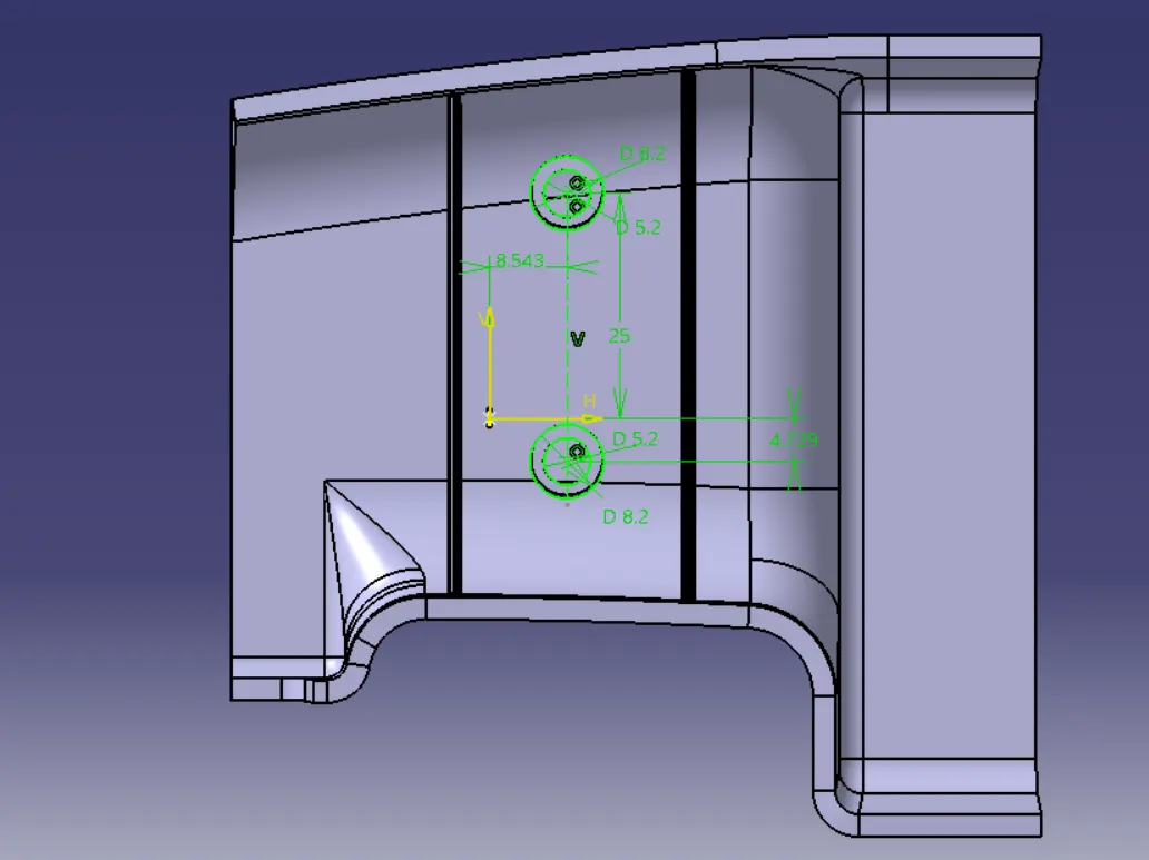
· Sketch the inner circle 5.2mm & outer circle to 8.2mm
· Pad the sketch to a height of H= 5*2.5=12.5mm & extend the pad to 3mm to other side & later using Boolean operation union trim can be used.
· Now apply the draft angle of 0.5 degree.
· Apply the fillets of 0.25mm on each side.
FINAL SOLID BODY
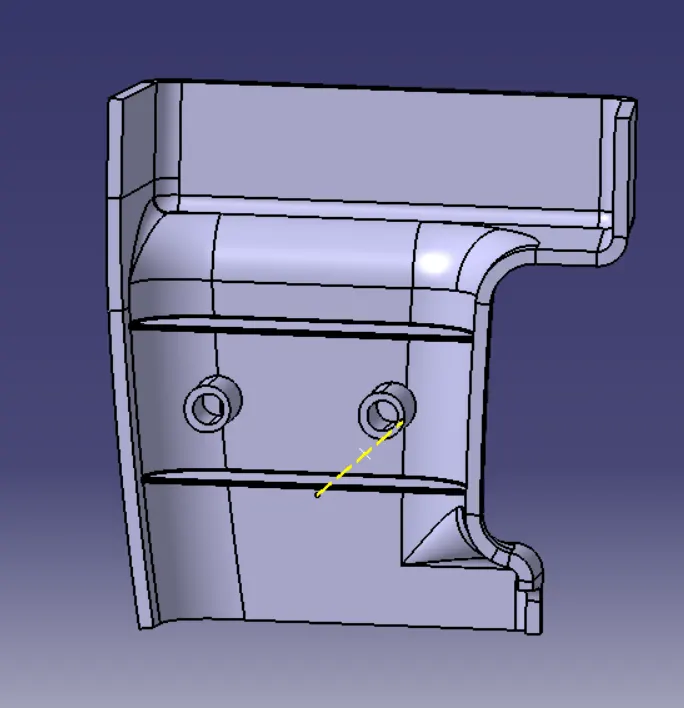
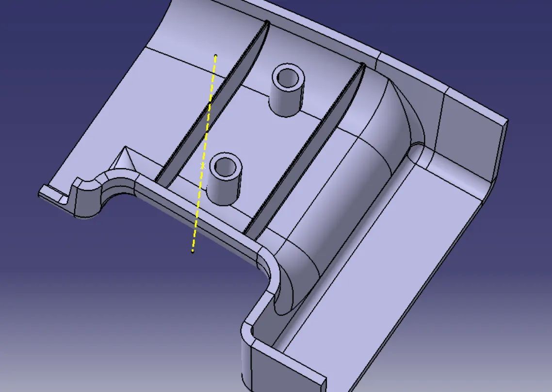
DRAFT ANALISYS OF SOLID BODY
CONCLUSION- I have successfully create Class B & Class C surface of the door handle ribs & screw boss feature attachment. by using the given Class A surface along the tooling axis.