Week 10- Assembly Workbench
Aim: To create assembly of Quick return motion mechanism and CV join mechanism
Procedure:
- Create sketches of the Part of the assembly
- Create all the parts in the Part workbench
- Assemble all the parts in the Assembly workbench with proper constraints.
- Create Drafting of all the individual parts and the assemble
Quick Return motion mechanism:
1. Slot
- Create the sketch of the slot as shown in the figure
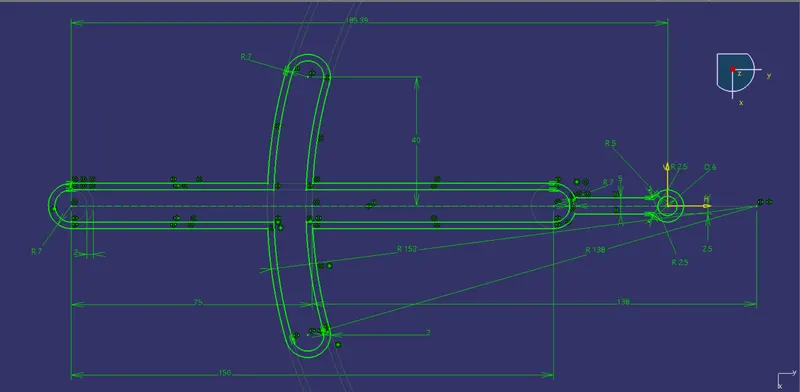
Figure: Sketch of Slot
- Further the sketch using the Pad command is padded to the thickness of 4mm.
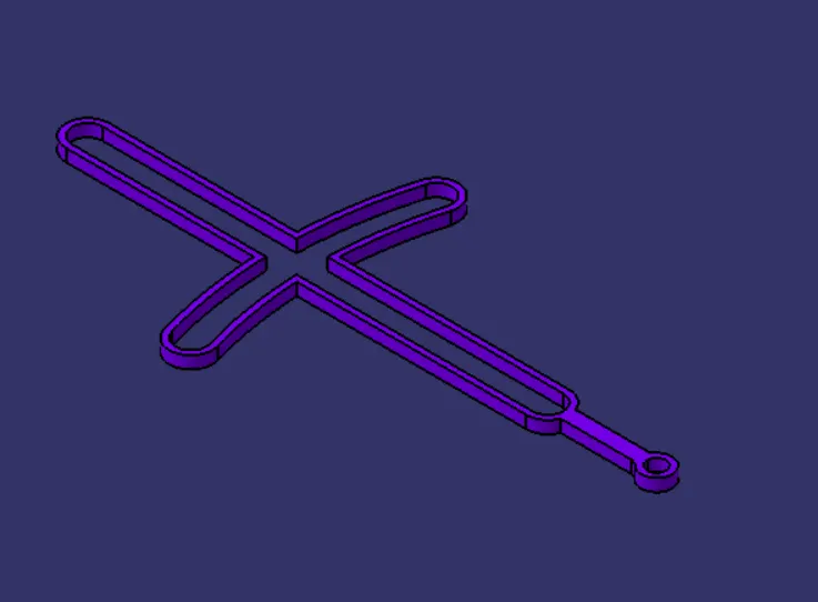
Figure: Isometric View

Figure: Front View
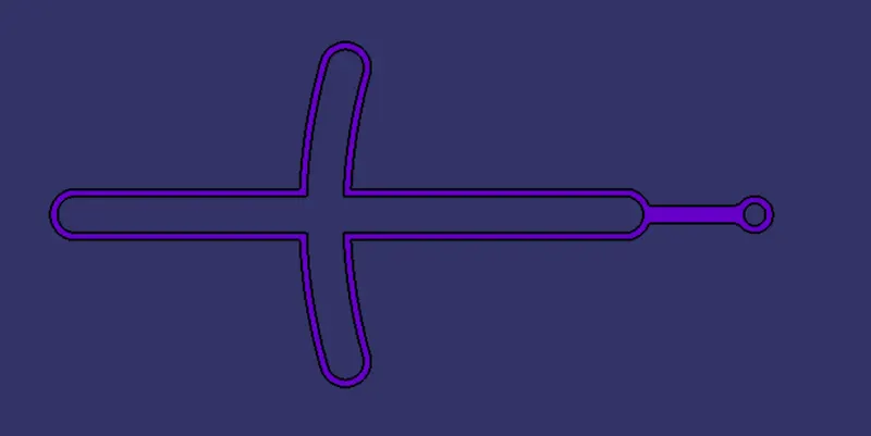
Figure: Top View
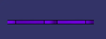
Figure: Side View
2. Slider
- Sketch of the slider is created as shown in figure
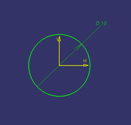
Figure: Slider sketch
- Further the Slider sketch is padded using the Pad command to the thickness of 50mm
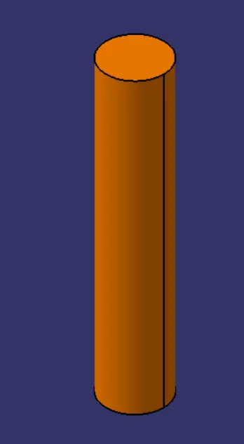
Figure: Isometric View
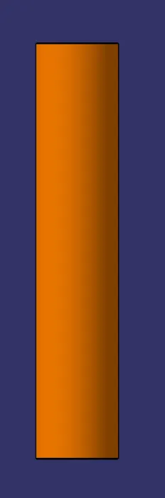
Figure: Front View

Figure: Top View
3. Rectangular Block:
- Sketch of the rectangular block is created as shown in figure
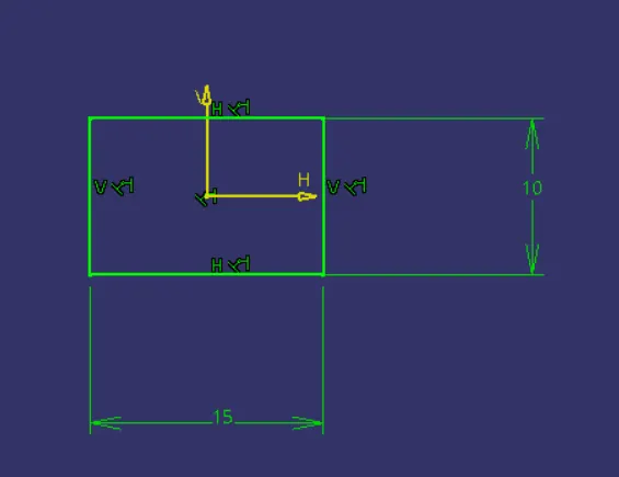
- Next, it is padded using the Pad Command to the thickness of 15mm
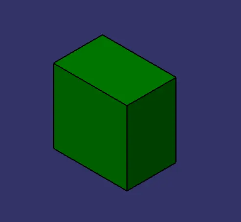
Figure: Pad of sketch 1
- Further on the upper face of the padded block a circle of 6mm diameter is created
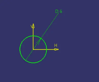
Figure: Sketch 2
- Next, a pad of variable limit is created of 6mm and 41.5mm as the first and second limit as shown in figure
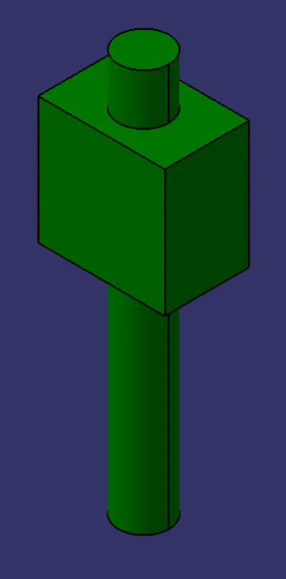
Figure: Isometric View of Rectangular Block
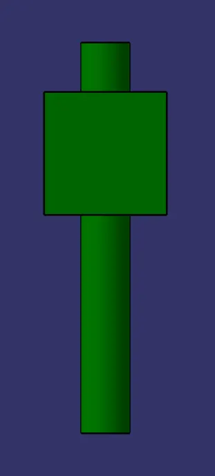
Figure: Front View
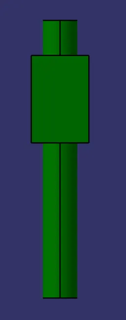
Figure: Side View
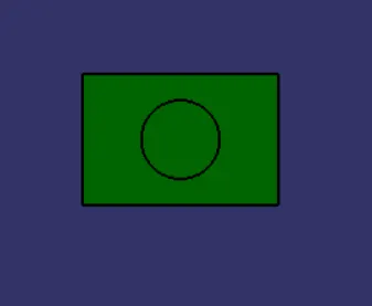
Figure: Top View
4. Cylindrical Block
- sketch of the Circle of 25mm diameter as shown in figure
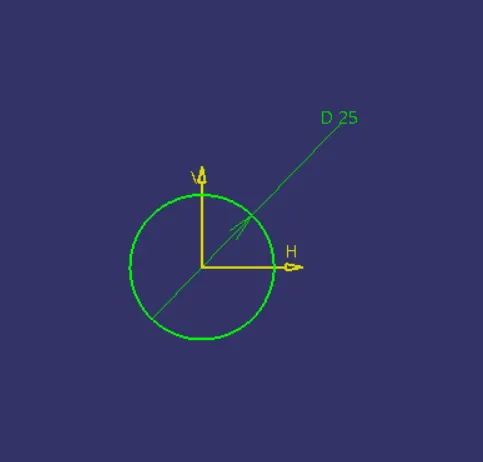
Figure: Sketch 1
- Further the sketch is padded using the Pad Command to the depth of 20mm
- Next, another sketch of circle of 6mm diameter is created on the upper face of the cylindrical block
- The created sketch is padded to the thickness of 8mm
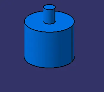
Figure: Isometric View
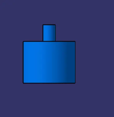
Figure: Front View
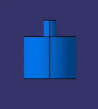
Figure: Side View
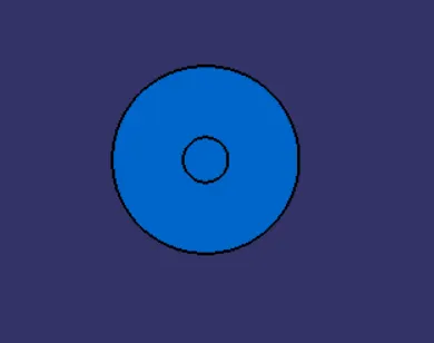
Figure: Top View
5. Connecting Rod
- Sketch of the connecting rod is crearted as shown in figure
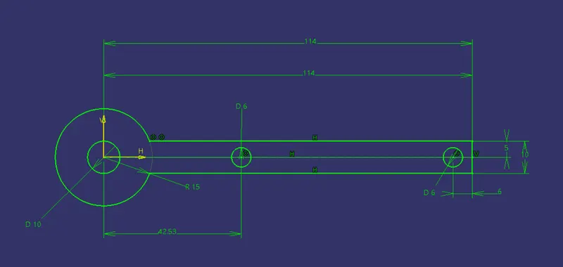
Figure: Connecting Rod
- Further, it is padded using the MultiPad Command to the required depth
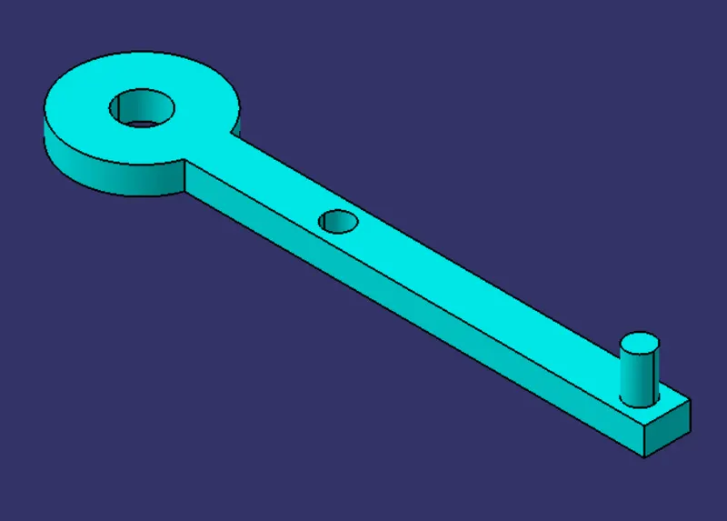
Figure: Isometric View

Figure: Front View
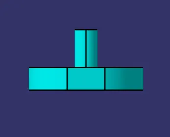
Figure: Side View
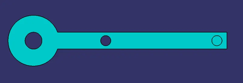
Figure: Top View
Quick Return motion mechanism Assembly:
- All the parts of Quick return motion Mechanism are to be assemble in the Mechanical Assembly workbench.
- Indivudual parts of the Quick return motion Mechanism are brought into the Product file using the Existing Component Command.
- Using of the Proper constraints and Smart move command all the parts are arranged in the assembly.
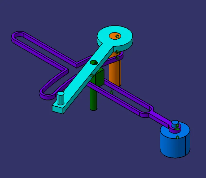
Figure: Isometric View
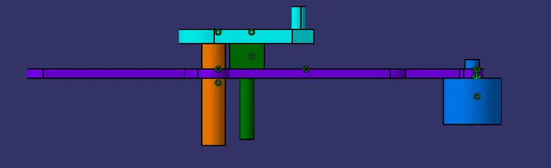
Figure: Front View
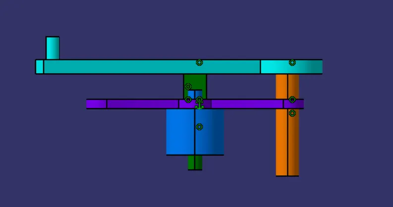
Figure: Side View
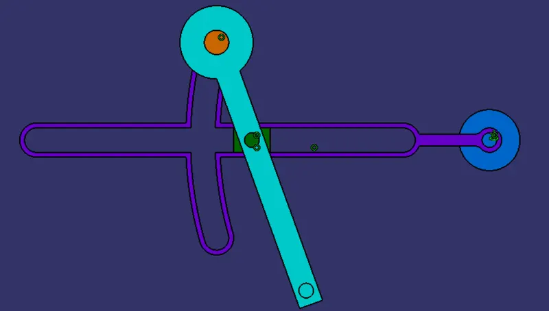
Figure: Front View
CV-Joint Mechanism:
1. Block:
- Sketch of circle of 50mm diameter is created as shown in figure
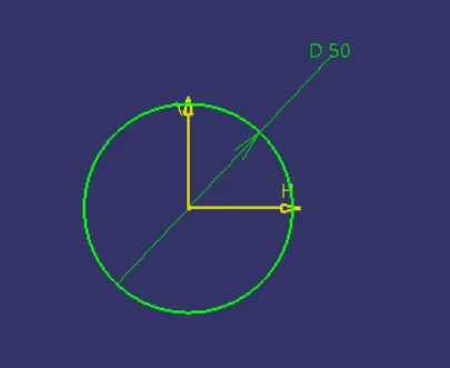
Figure: Sketch 1
- Further, Pad definition is given along the mirror extend on the above sketch to the length of 50mm
- Another smillar sketch of 50mm diameter circle is created and padded perpendicular to above created pad.
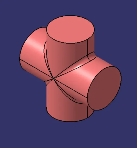
Figure: Isometric View
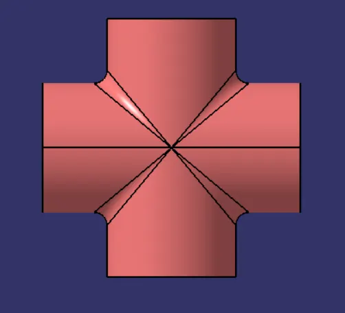
Figure: Front View
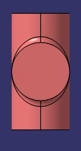
Figure: Side View
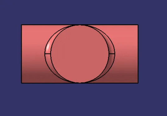
Figure: Top View
2. I-Cap
- Sketch of the Base of I-Cap is created as shown in figure
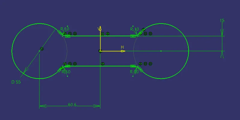
Figure: Sketch 1
- Using the Pad Command, pad the above sketch to the thickness of 20mm and provide a hole of 50mm diameter on both circular dics of the I- cap
- further sketches are created and padded and proper fillet are provided on it as required
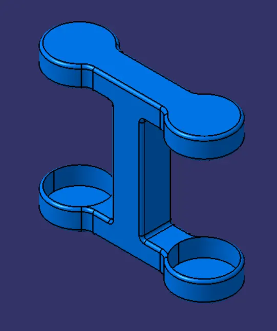
Figure: Isometric View
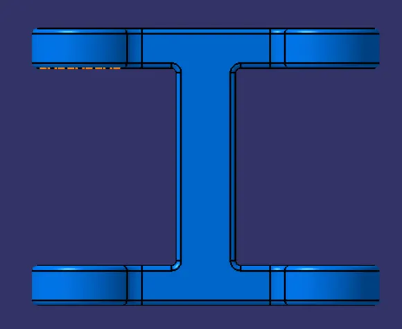
Figure: Front View
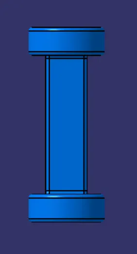
Figure: Side View

Figure: Top View
3. C-Cap
- Appropriate sketches are created along with sketch for the pocket as shown in figure
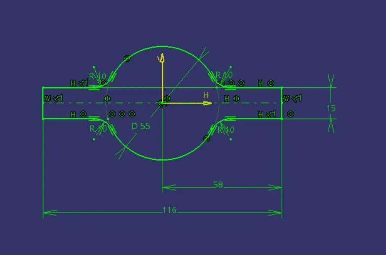
Figure: Sketch 1
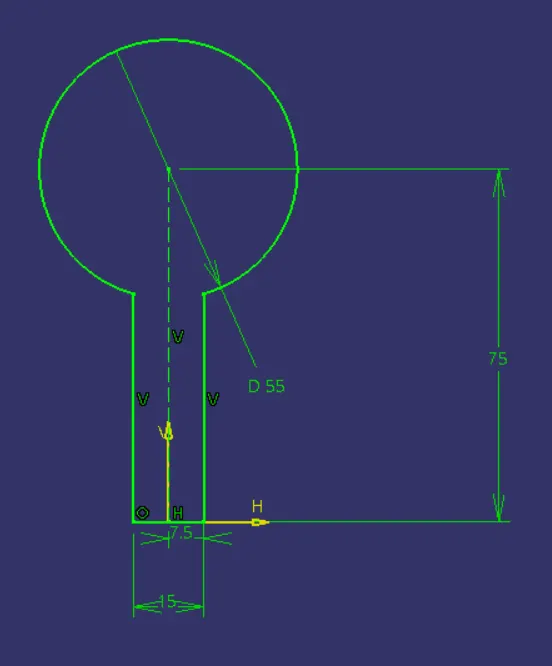
Figure: Sketch 2
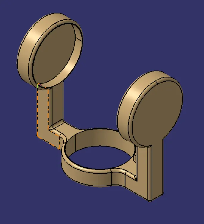
Figure: Isometric View
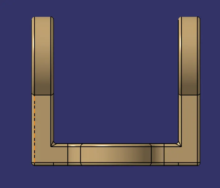
Figure: Front View
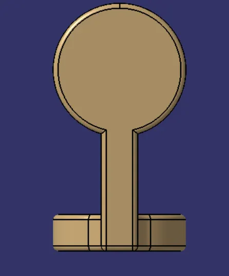
Figure: Side View
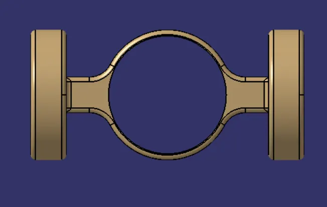
Figure: Top View
Assembly of CV-Joint:
All individual parts are assembled with proper constraints in the Assembly Workbench
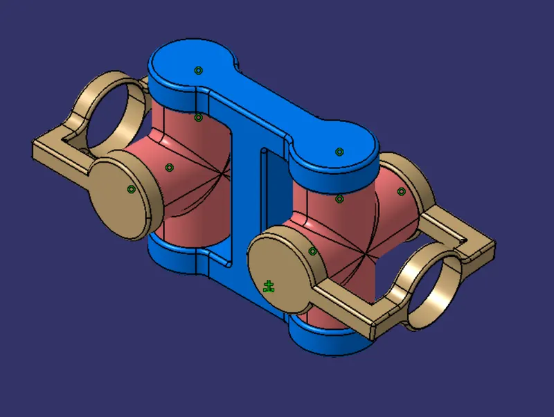
Figure: Isometric View
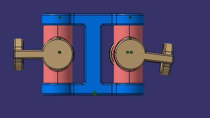
Figure: Front View
Lastly, 2D Drafting of all the individual parts and assembly of both Quick return motion mechanism and CV-Joint is created on the Drawing workbench with proper dimensions shown.