Week 1 Stress Concentration on a Plate with hole
OBJECTIVE :-
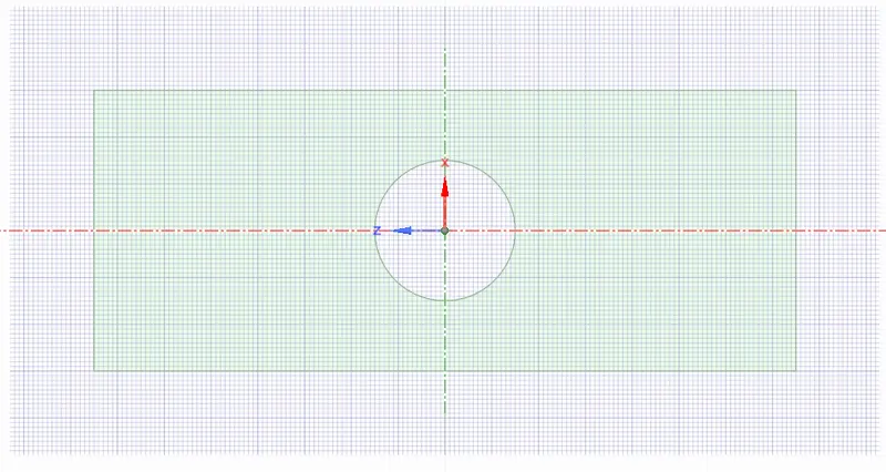
1.Design a plate with a hole and Determine the maximum deformation and stress developed in the model among the two plates with dimension and boundary conditions given below :-
CASE -1
Plate dimensions:
Length=300mm
Height=120mm
Thickness=30mm
Circular Hole at the center:
Diameter=60mm
CASE -2
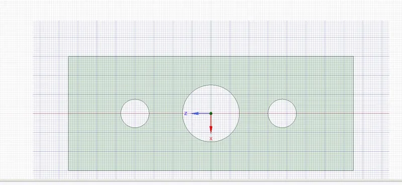
Plate dimensions:
Length=300mm
Height=120mm
Thickness=30mm
Circular Hole at the center:
Diameter=60mmsmaller holes 90mm away from the center with Diameter=30mm
BOUNDARY CONDITIONS:
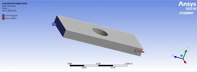
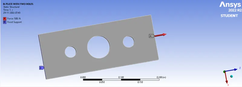
Plate fixed at left face.
Load of 500N on the right face.
2. Understand the GUI of Ansys Workbench
3. work on Space claim to sketch a geometry.
4. Apply boundary conditions as given in the question.
5. Mesh the model and solve as per the boundary conditions and perform static structural analysis to calculate true stress, total deformaton in order to understand the which of the design sould be chosen in different case scenario.
THEORY
1. In FEA any simulation can be done in the following steps:-
a. Understanding the physics of the problem
b. Preprocessor
c. Solving
d. Post Processor
2. Equivalent stress is used when there is a multiaxial stress state with multiple stress components acting at the same time in the structure. In such case we can use selected criterion to transform the whole stress tensor into a single equivalent component that can be treated as a tensile stress and thus compared with material’s strength easily. Various criteria may be utilize but among them there is one with incomparably larger popularity than the others - von Mises yield criterion or otherwise maximum distortion energy criterion. It’s commonly used in engineering as for example Finite Element Analysis programs use it as a default stress measure.
3. Stress Concentration Stress Concentration is the accumulation of stress in a body due to sudden change in its geometry.Change in geometry such as cracks, sharp corners, holes and decrease in the cross section area.
In order to consider the effect of stress concentration and find out localized stresses, a factor called stress concentration factor is used. It is denoted by Kt and defined as,
where σo and τo are stresses determined by elementary equations and σmax and τmax are localized stresses at the discontinuities. The subscript ‘t’ denotes the ‘theoretical’ stress concentration factor. The magnitude of stress concentration factor depends upon the geometry of the component.
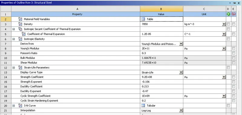
4. Material Used Structural Steels
PROCEDURE :
Preprocessor
1. The ansys workbench was opened and static structural system was selected to under take the simulation.
2. As per the dimension given in the question the model were created in the space claim. Following are the case wise sketch.
CASE -1
CASE -2
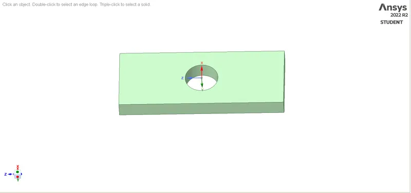
3. Post generatin the sketch, with the help of pull command the 3D model were created for both the case.
CASE -1
CASE -2
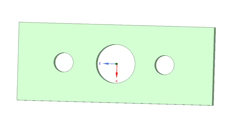
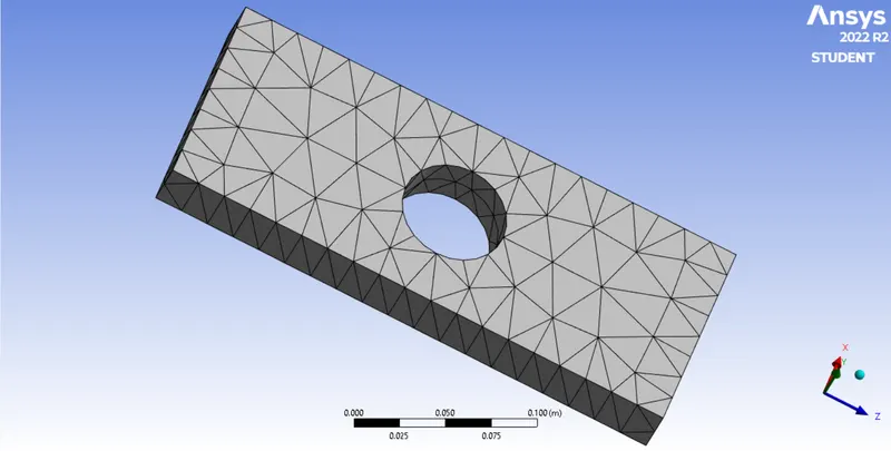
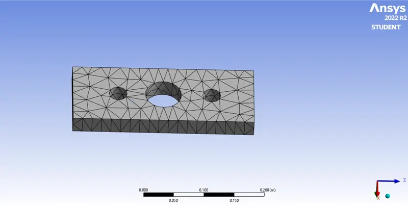
4. post generatin the 3d model, the meshing was undertaken. model were meshed with tetra fine mesh.
CASE -1
CASE -2
Solving
5. Post generation of mesh the boundary conditions were given to the models
CASE -1
CASE -2
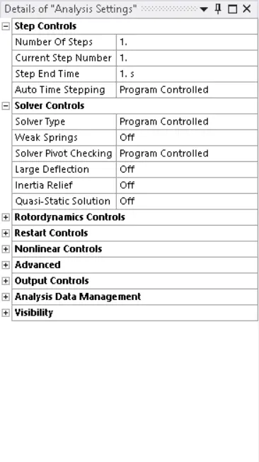
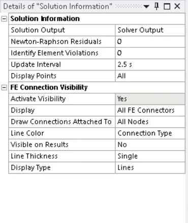
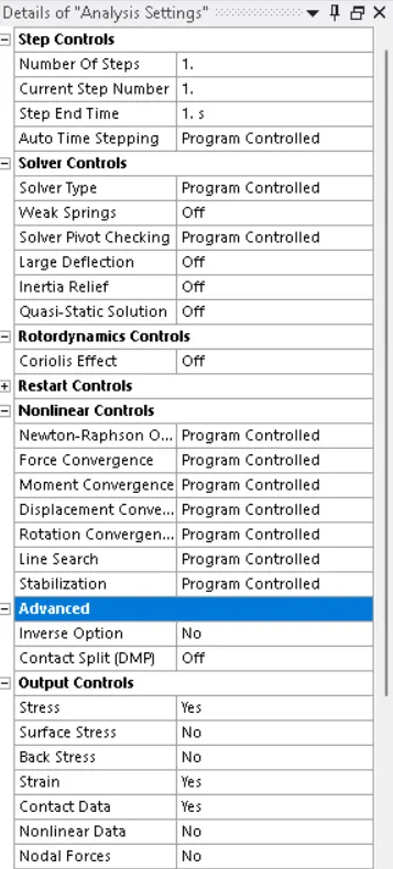
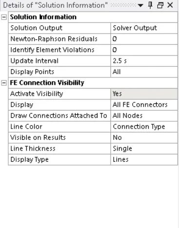
6. The following are the analysis setting and solution information for both the models.
CASE -1
CASE -2
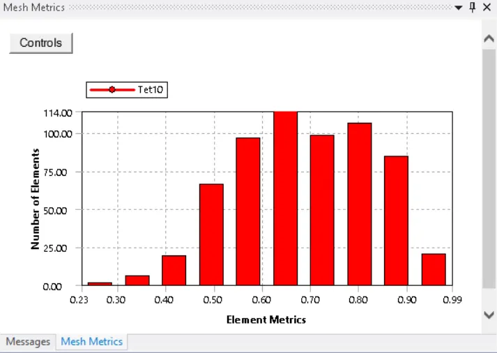
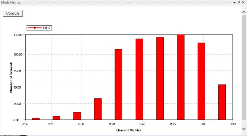
7. post this the following were the mesh element quality matrix
CASE -1
CASE -2
8. Final step was to calculate Von Mises Stress and Total deformation.
Post Processor
9.The output are as follows :-
| SL.NO | TYPE | Equivalent Stress(MAX) | Equivalent Stress(MIN) | Total Deformation(MAX) | Total Deformation(MIN) |
| 1 |
CASE-1 |
0.58316MPa | 0.042827MPa | 0.0002731mm |
0 |
| 2 |
CASE-2 |
0.56317MPa | 0.014613MPa | 0.00028759mm | 0 |
Animation of the Simulation
Case 1 :-
Stress
Total deformation
Case 2 :-
Stress
Total deformation
OBSERVATION
1. It can be seen from the table that the MAX and IN stress generation in plate with single hole is more than that in plate with multiple hole. Reason can be attribuable to the lagre disturbance in stress flow in case 1 as compares to case 2.
2. It is also observed that the Total Deformation in case 1 is less than that in case 2. This is because lower availability of material in case 2.
3. From the analysis simulation it can be seen that the max stress is present at the junction of hole in both the cases.
4. Major deformation can be seen localised at the end portions the plate in both the cases
5. Zero deformation can be seen at the postitions which is closed to fixed support.
CONCLUSION
1. Analysis Standpoint :- From the table provided at the post processor it is clear that plate with multiple hole to be considered from analysis standpoint. Since the Equivalent Stress is lower in comparision with the same in plate with single hole. Lower generation of equivalent stress implies safer operation of component.
2. Manufacturing Standpoint:- from the manufacturing Stand Point Plate with single hole is to be considered due to the following reasons :-
a. Easier to manufacture
b. Less time taken in manufacturing
c. Loss of material is less.