Week 2.1-Air standard Cycle
Aim:- Write code that can solve an otto cycle and make plots for it. Following are the requirements:-
- code should create a PV diagram.
Theory:- Otto cycle was discovered by Nikolaus Otto. Otto Cycle is an idealised thermodynamic cycle which describes the functioning of spark ignition internal combustion engine.This cycle has application in the Automotive Industry. The function of the cycle is to convert one form of enery to another transfer. As basically Chemical Energy to Thermal Energy. Assumptions being used on the cycle used in the engine to convert it to air standard otto cycle :-
(a) Specific Heat is considered as constant and not a function of temperature.
(b) Suction and exhaust stroke are being neglected.
(c) Working Fluid is being considered as ideal gas.
(d) Combustion and Exhaust process are replaced by isochoric heat addition and isochoric heat rejection.
(e) All the process taking place are considered to be reversible.
(f) Compression and Expansion are considered to be adiabatic ie no heat transferfrom the system.
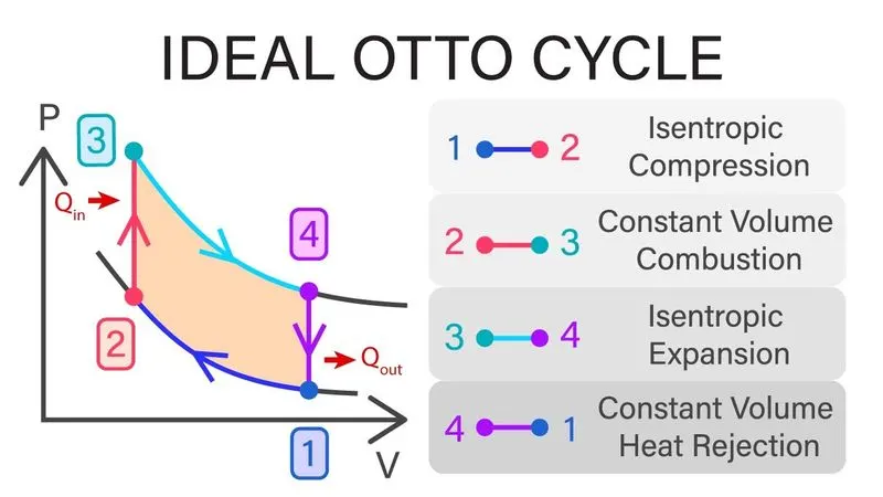
Otto Cycle employs 4 processes:-
(a) Process1-2- Reversible Adiabatic Compression (or Isentropic Compression). Here in this process working fluid is compressed in the piston cylinder arrangement by keeping PV^gama = Constant and reversible throught the process. The piston moves from lower date center to top date center and the crank rotated by 180degrees. This is considered as 2nd Stroke of the cycle used in spark ignition Engine. The volume of the working fluid is compressed till the same becomes equal to clearance volume.
(b) Process2-3- Reversible Isochorice Heat Addition. After the compression the working fluid is given additional energy keeping its volume to be constant. Temperature of the working fluid after this process is the maximum temperature of the cycle. The same is considered essential to vary the effeciency of the cold air standard otto cycle.
(c) Process3-4- Reversible Adiabatic Expansion(or Isentropic Expansion). Energy stored in the working fluid is used to drive the crank which intern give the output in the form of work.Here in this process working fluid is expanded in the piston cylinder arrangement by keeping PV^gama = Constant and reversible throught the process.This is considered as 3rd Stroke of the cycle used in spark ignition Engine.
(d) Process 4-5 Reversible Isochorice Heat Rejection. Balance energy left in the working fluid after giving the output as work rejected to the surrounding. This essential step to justify the 2nd Law of thermodymanic. After loosing the energy working fluid is restored back to its inital state.
Equations involved :-
1. Working Fluid follows ideal gas equation hence it follows :- PV=MRT.
2. It follows reversible adiabatic process from 1-2:- P1V1^gama = P2V2^gama
3. As the heat addition is isochoric from process 2-3:- P2/T2=P3/T3
4. It follows rev adiabatice expansion from process 3-4:- P3V3^gama =P4V4^gama
5. To calculate the volume as per the angle trace by the crank :-V=Vs(1+0.5(Cr-1)(R+1-cos(theta)-(R^2- Sin(Theta)^2)^0.5))
6. To calculate the vswept vs=0.785*bore^2*Stroke
7. To calculate Vclearance= VC= Vs/(cr-1)
8. for v1 =Vs+Vc
Code :-
clc
clear all
close all
% initial given data declaration
bore=0.1;
stroke=0.1;
t1= 450;
p1=101325;
t3=1500;
cr=12;
gama=1.4;
c_rod=0.15;
%calculation of clearance volume and swept volume
v_swept=0.785*bore^2*stroke
v_cl=v_swept/(cr-1)
v2=v_cl
v1=v_cl+v_swept
%compression stroke data analysis
const=p1*v1^gama;
v_comp=e_kinematics(bore,stroke,c_rod,cr,180,0);
p_comp=const./(v_comp.^gama)
%as per adiabatic condition p1*v1^gama=P2*v2^gama
p2 = p1*(v1/v2)^gama
t2=(v1/v2)^(gama-1)*t1

% ap per conditions of Ideal gas for iso choric process p3/t3=p2/t2
p3=(p2/t2)*t3
v3=v2
%compression stroke data analysis
const=p3*v3^gama;
v_exp=e_kinematics(bore,stroke,c_rod,cr,0,180);
p_exp=const./(v_exp.^gama)
v4=v1

p4 = p3*(v3/v4)^gama
t4=(v3/v4)^(gama-1)*t3

% Graph tracing of all processes
figure (1)
hold on
plot(v1,p1, '*','color', 'r')
plot(v_comp, p_comp, 'color', 'r')
plot(v2,p2,'*', 'color', 'r')
plot(v3,p3, '*','color', 'r')
plot(v_exp,p_exp, 'color', 'r')
plot(v4,p4, '*','color', 'r')
plot([v2 v3],[p2 p3])
plot([v1 v4],[p1 p4])
xlabel('volume')
ylabel('pressure')
Function Code :-
function [v]=e_kinematics(bore,stroke, c_rod, cr,start, stop)
a=stroke/2;
R=c_rod/a;
theta=linspace(start, stop, 100)
vs=0.785*bore^2*stroke;
vc=vs/(cr-1);
t1=0.5*(cr-1);
t2=R+1-cosd(theta);
t3=(R^2-sind(theta).^2).^0.5;
v=(1+t1*(t2-t3))*vc
end
Code Explaination :-
1. For the initiation in the code we declare 'Clear all, Close all and clc'. Next we will assign the given data required for the analysis of Air Standard otto Cycle such as bore, stroke, compression ratio, connecting rod length,gama, highest temperature in the cycle Start angle and Stop angle.
2. Now we will assign the values for Vswept and V Clearance to calculate V1 and by using the expressions for thermodynamic relations we calculate the points for P1V1, P2V2, P3V3 and P4V4.
3. To trace the line for the both the adiabatic processed we declare the function e_Kinematics to calculate the volume for every angle trace by the crank. For compression we need to assign the values for the angle between 180 to 0 degrees. For Expansion we need to assign the values of angles between 0 to 180. After getting the output of the function we generate the corresponding Pressure values in both the adiabatic Processes by using thermodynamic relations for adiabatic processes.
4. Last Step would be to plot every point and line calculated during the above analysis.
Output Generated :-
Graph of the output
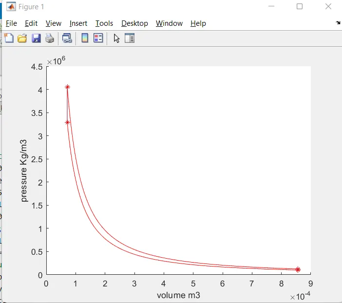
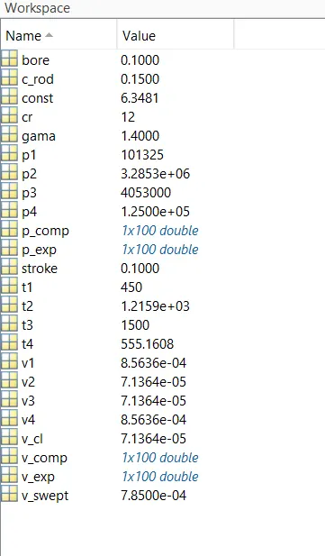
Explaination for the output :- After declaring all the thermodynamic relations in the code it can be seen that value of p2 is greater that p1 which justified as process 1-2 is a compression process. As the process 1-2 & 3-4 are reversible adiabatic processes it can be noticed that the traced curve for process 1-2 is following PV^gama =Constant. It was declared initially that T3 is the highest temp therefore from the values of temperature in the output no temp is higher than T3. Process 2-3 and 4-1 both are const volume process and it can be seen from the graph that those two process are tracing a straigh t line.
Error Incured while Coding :-
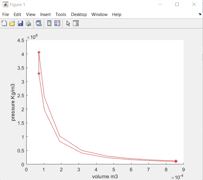
1. While declaring theta in the function e_kinematic the total no of values for theta was initially declared as 10.
Due to this discreete values of theta the graph for both the compression and expansion process was traced as non smooth.
2. The same was traced smooth by increasing the no of values to 100 for theta. The correct graph for the output for cold air standard otto cycle is placed below