Week 1 To perform stress analysis of spur gear for three different material in ANSYS
OBJECTIVE:- To perform stress analysis of spur gear for three different material in ANSYS
OBJECTIVE 1:-
- Case 1: Using Cast Iron(ductile) as a material, carry out a static structural analysis to find out Equivalent stress, Total deformation and Stress intensity(Learn about what stress intensity is). Find a location for possible fracture
- Case 2: Using Cast Steel as material, perform the same analysis for the results as in Case 1.
- Case 3: Using Cast Bronze as material, perform the same analysis for the results as in Case 1.
Stress intensity:-
The stress intensity factor, K, is used in fracture mechanics to predict the stress state ("stress intensity") near the tip of a crack or notch caused by a remote load or residual stresses. It is a theoretical construct usually applied to a homogeneous, linear elastic material and is useful for providing a failure criterion for brittle materials, and is a critical technique in the discipline of damage tolerance. The concept can also be applied to materials that exhibit small-scale yielding at a crack tip.
The magnitude of K depends on specimen geometry, the size and location of the crack or notch, and the magnitude and the distribution of loads on the material. It can be written as
`K = sigma root "(pi alpha) *f* (alpha/W)`
where `f*(alpha/W)` is a specimen geometry dependent function of the crack length, `alpha`, and the specimen width, `W`, and `sigma` is the applied stress.
PROCEDURE:-
Case 1: Using Cast Iron(ductile) as a material
- Open Ansys Workbench and choose static structural.
- In the Engineering data, the materials can be found in Granta Design sample materials, select the material Cast iron (ductile) with default values.
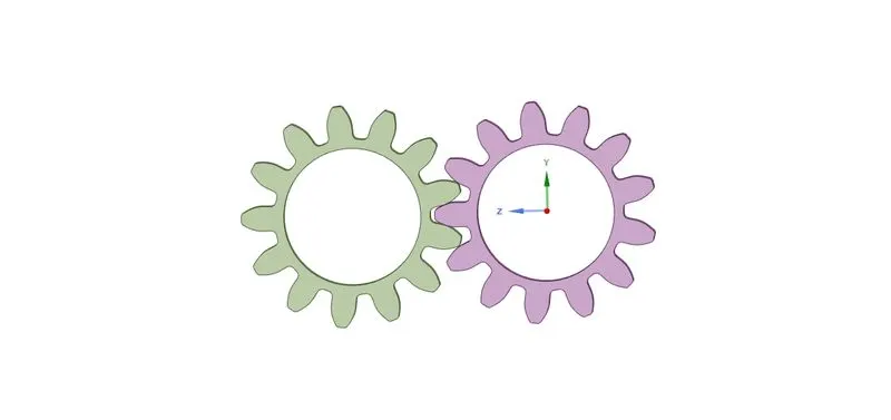
- For the geometry, right-click and import the given Spur_Gear.stp and open the space claim to check it.
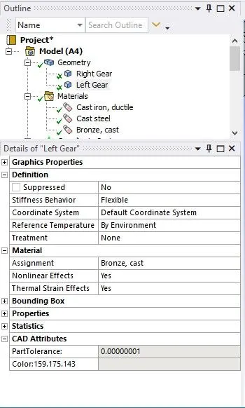
- Now in the workbench goto Model -> Edit, in the model window check the Geometry for the material and assign Cast Iron (ductile) to both the part
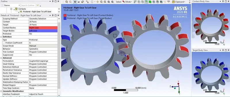
- For contact, choose the Contact bodies as faces of the tooth of the right gear and Target Bodies as faces of the tooth of left gear, Type = Frictional, Behaviour = Symmetric, Formulation = Augmented Lagrange, Interface treatment = Adjust to touch
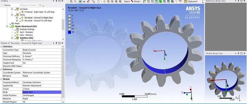
- To define the nature of the joint, create joint under connection for each part and assign Connection type = Body to ground, Type= Revolute and Scope= Choose the inner surface of the gear.
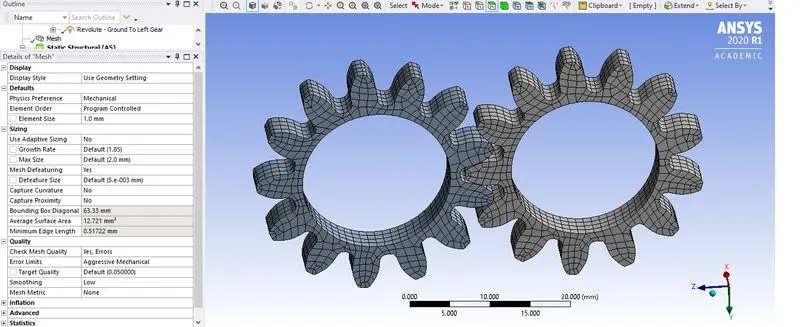
- Now click on the mesh, provide Element size= 1mm, Use Adaptive Sizing = No, Smoothing = Low and generate the mesh.
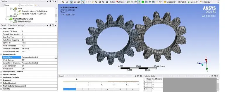
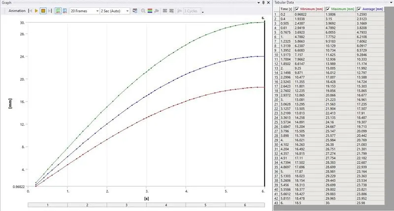
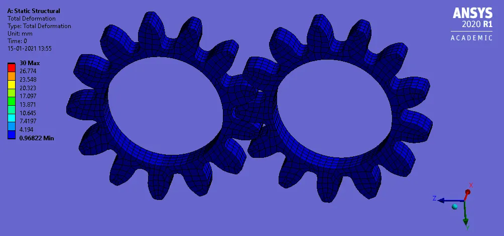
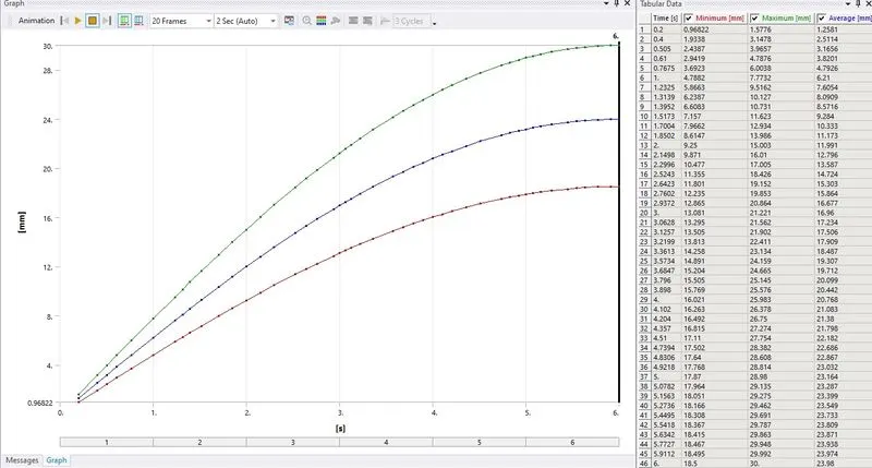
- For Analysis setting, Number of steps = 6 (select all the 6 steps shown in the graph), Large Deflection = On, Auto Time Stepping= On, Define by= Time, Carry Over Time Step= On, Intial Time Step= 0.2 sec, Minimum Time Step= 5e-2 sec, Maximum Time Step= 0.5 sec
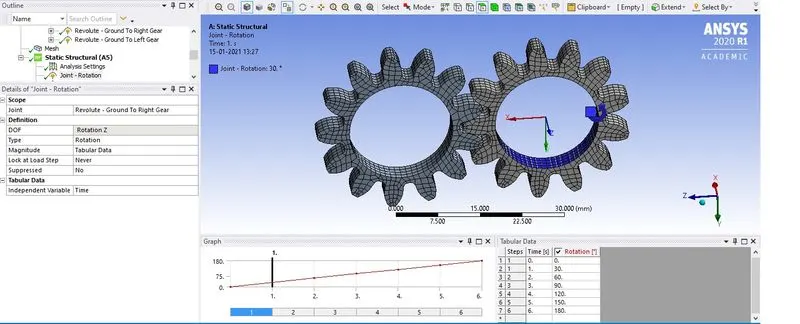
- Now to provide rotation Joint load, Static Structural -> Insert -> Joint Load, Joint= Revolute- Ground to Right Gear, Type= Rotation, Magnitude= Tabular Data, provide the degree from 0 to 180 in 30 increments for the 6 steps in the tabular data.
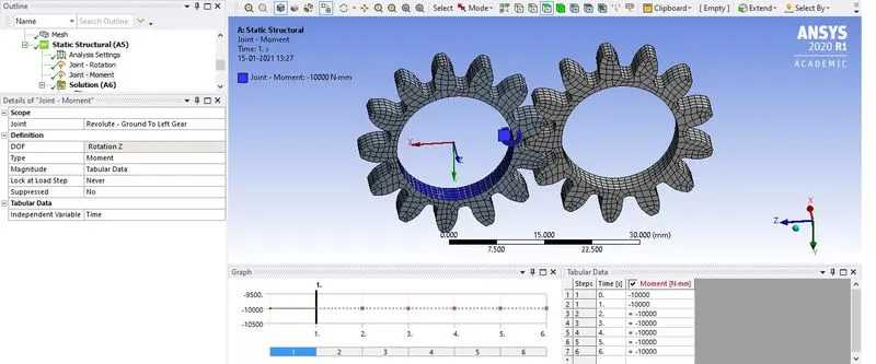
- To provide moment Joint load, Static Structural -> Insert -> Joint Load, Joint= Revolute- Ground to Left Gear, Type= Moment, Magnitude= Tabular Data, provide the constant moment of 10 N-m for all the 6 steps. Check the rotation of the 2 gear for clockwise and anticlockwise, the direction can be altered by providing -ve sign.
- For the solution create the required output request and solve for the same.
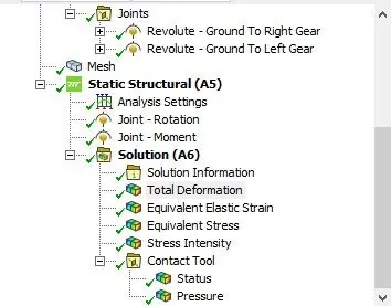
Case 2: Using Cast Steel as material, perform the same analysis for the results as in Case 1
- In the Engineering data, the materials can be found in Granta Design sample materials, select the material Cast steel with default values.
- Now in the workbench goto Model -> Edit, in the model window check the Geometry for the material and assign Cast steel to both the part
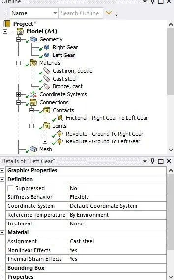
- All the condition which is given in CASE 1 will be applied to CASE 2
Case 3: Using Cast Bronze as material, perform the same analysis for the results as in Case 1.
- In the Engineering data, the materials can be found in Granta Design sample materials, select the material Cast steel with default values.
- Now in the workbench goto Model -> Edit, in the model window check the Geometry for the material and assign Bronze, Cast to both the part
- All the condition which is given in CASE 1 will be applied to CASE 3
RESULT:-
Total Deformation:-
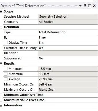
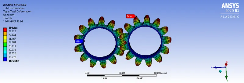
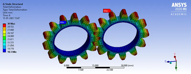
Case 1:- Caste Iron (Ductile)
Case 2:- Cast Steel
Case 3:- Bronze Cast
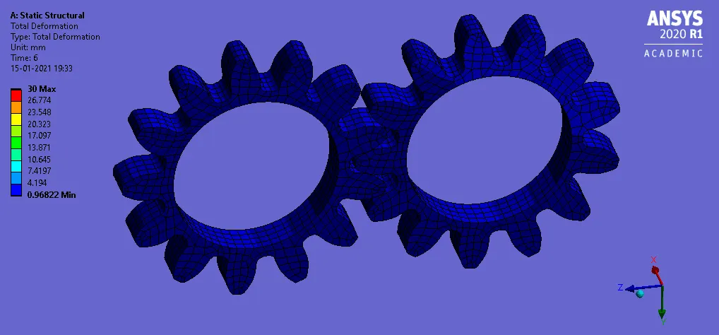
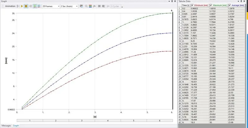
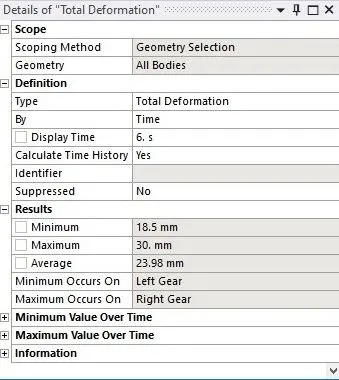
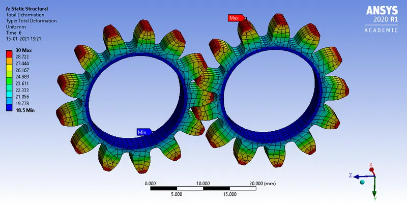
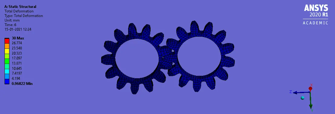
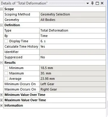
- The maximum total deformation of the gears for the 3 different material are same which is about 30 mm
STRAIN:-
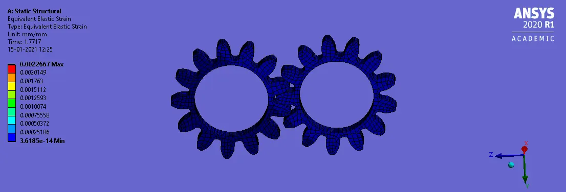
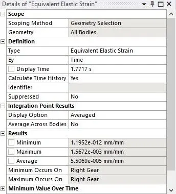
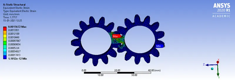
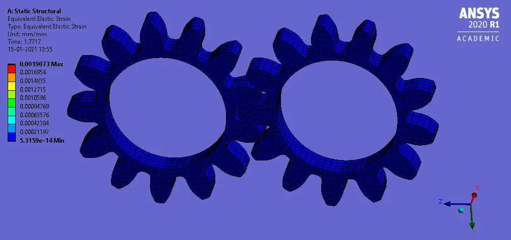
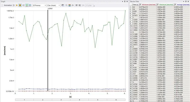
Case 1:- Caste Iron (Ductile)
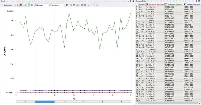
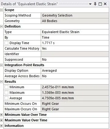
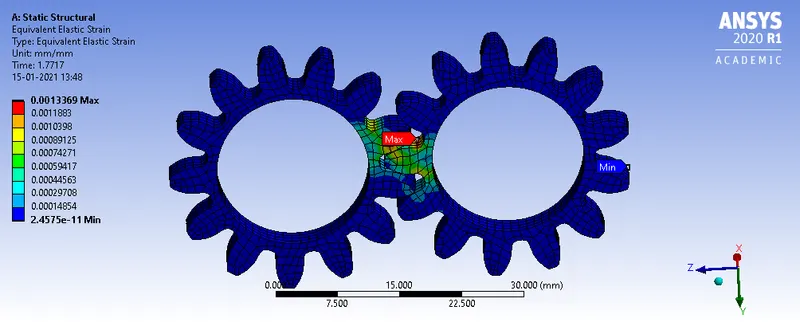
Case 2:- Cast Steel
Case 3:- Bronze Cast
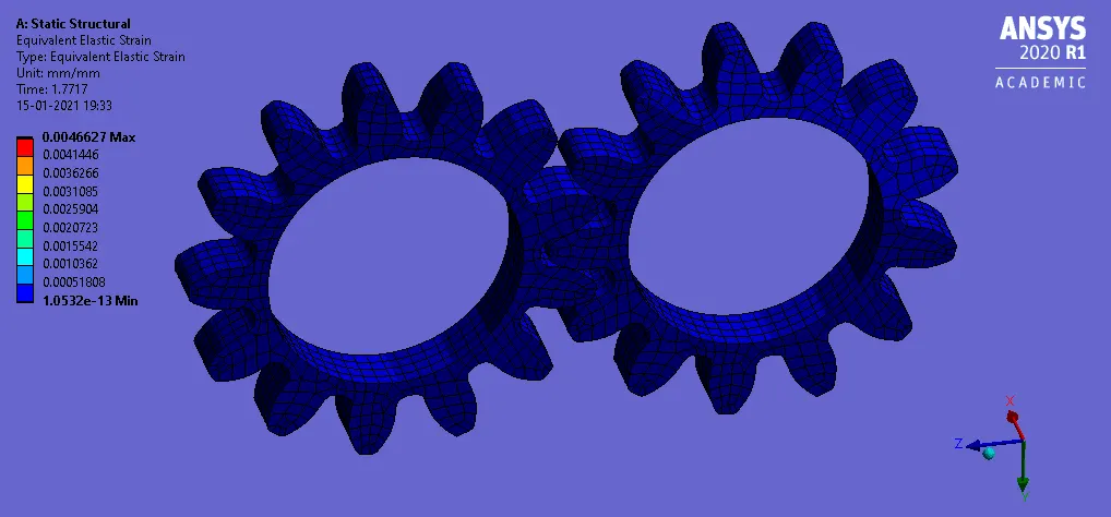
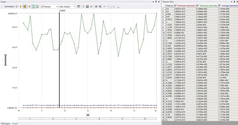
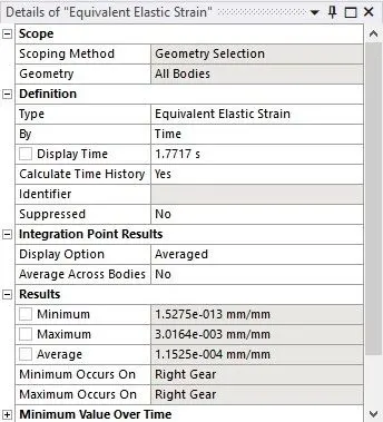
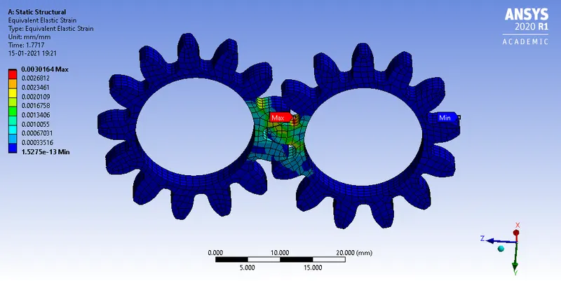
- Among the 3 different material the gear made up of Cast steel experience the least maximum strain that is of 0.0013369 and the Bronze cast experience the maximum highest strain that is of 0.0030164.
STRESS:-
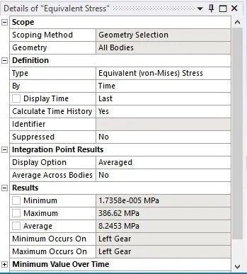
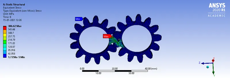
Case 1:- Caste Iron (Ductile)
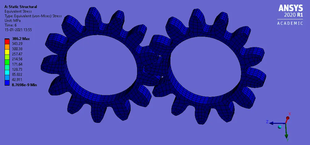
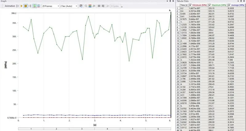
Case 2:- Cast Steel
Case 3:- Bronze Cast
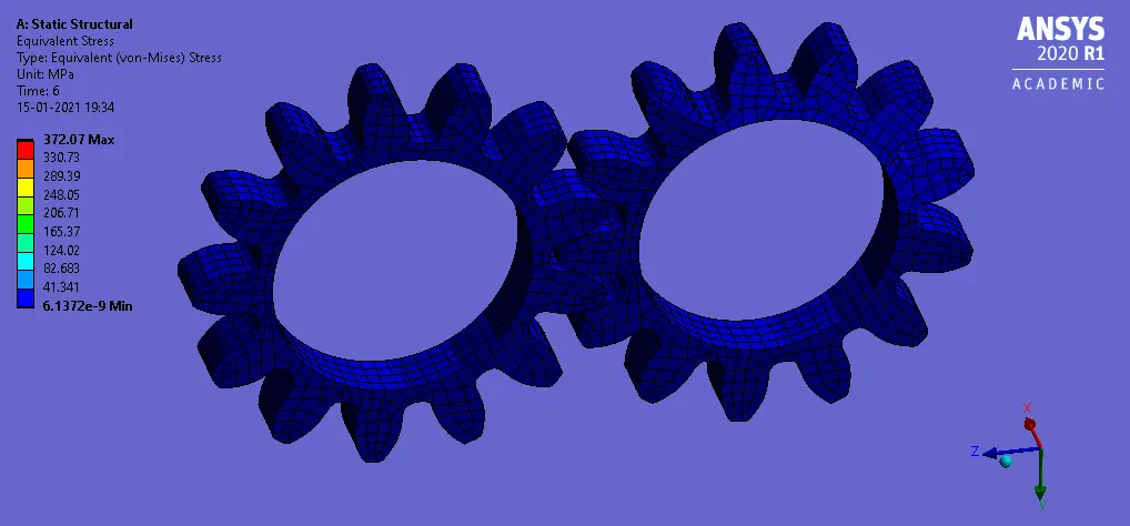
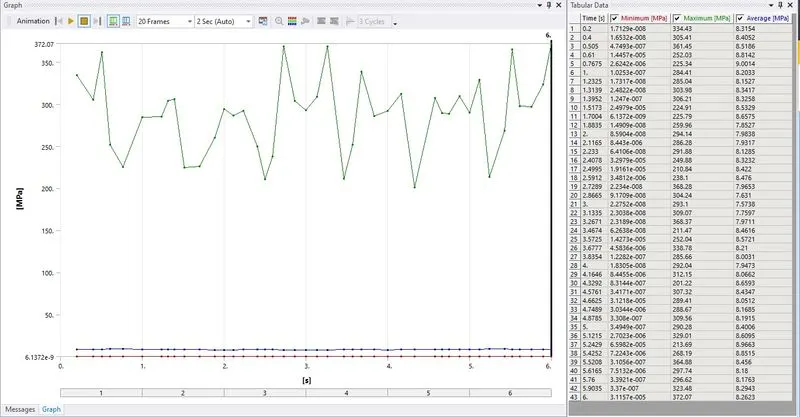
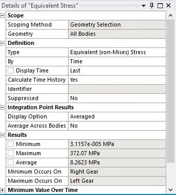
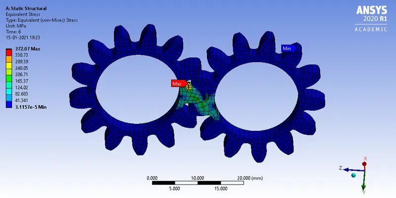
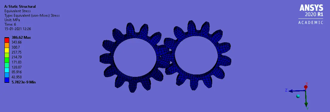
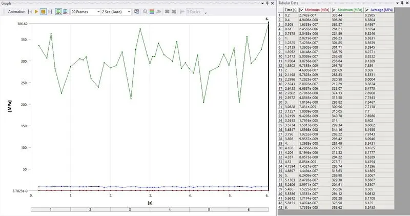
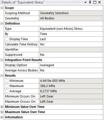
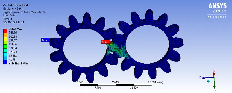
- From the 3 different material the gear made up of Bronze cast experience the least maximum stress of 372.07 MPa and the gear made up of Cast iron and Cast steel experience the near to similar amount highest maximum stress of 386.62 MPa and 386.2 MPa respectively.
STRESS INTENSITY:-
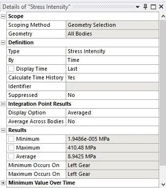
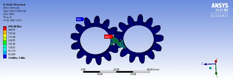
Case 1:- Caste Iron (Ductile)
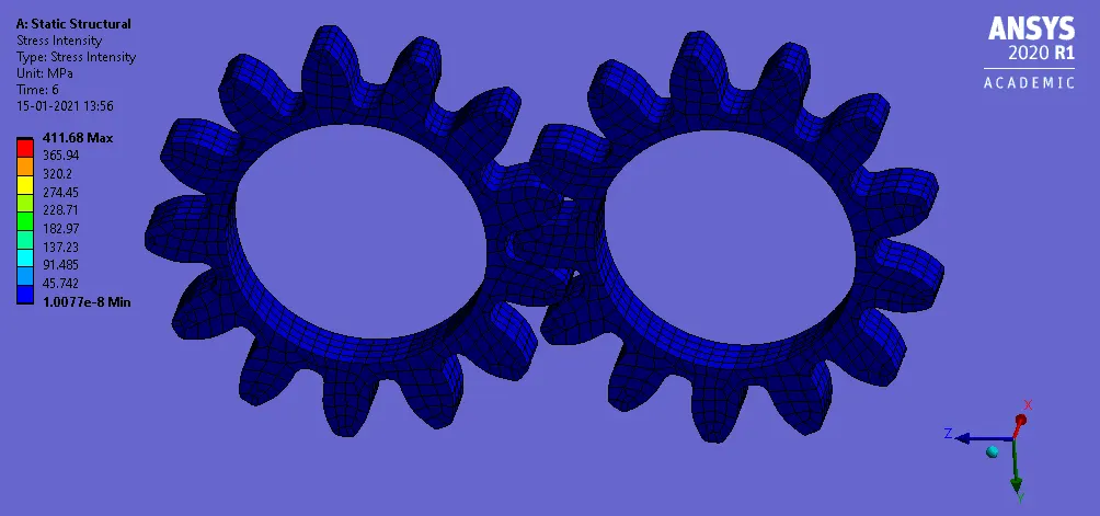
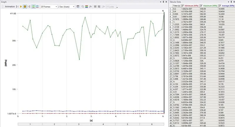
Case 2:- Cast Steel
Case 3:- Bronze Cast
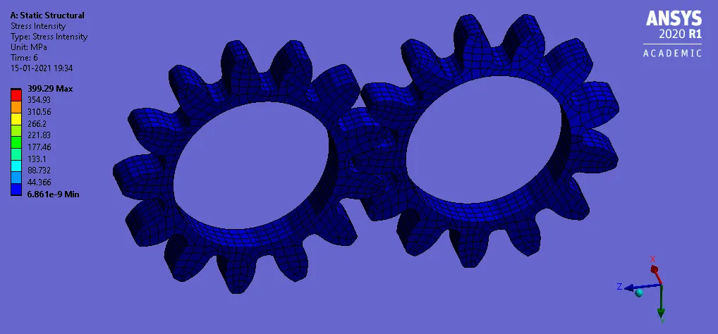
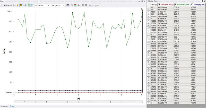

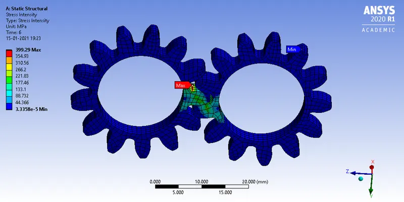
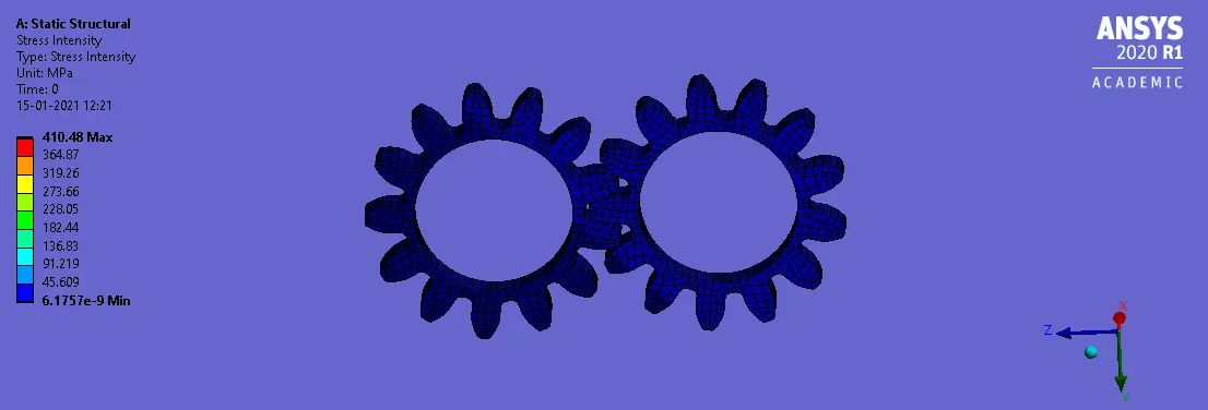
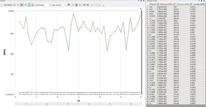
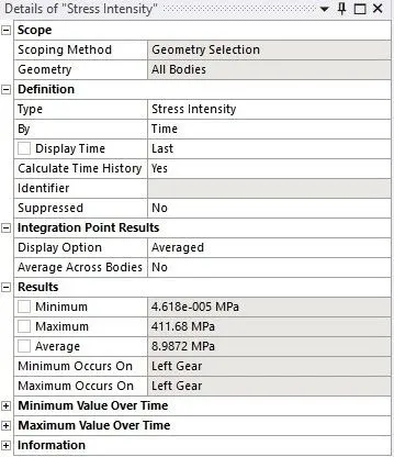
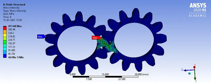
- Among the 3 different material the gear made up of Bronze cast experience the least amount of maximum stress intensity which is of 399.29 MPa while the gear made up of Cast steel experience the highest amount of maximum stress intensity which is of 411.68 MPa and Cast iron experiences 410.48 MPa.
- Location for possible fracture:- The fracture can be approximated to occur in the region where the stress intensity is maximum for the 3 different materials of the gear, in this case that is nearby where the gear flank meets the bottom land.
Objective 2: Write a detailed report comparing the results of the three cases and conclude which material would you recommend based on these results.
| CASE | Total Deformation in mm (Max) | Equivalent Elastic Strain in mm/mm (Max) | Equivalent (Von-Mises) Stress in MPa (Max) | Stress Intensity in MPa (Max) |
| Cast Iron (Ductile) | 30 | 0.0015672 | 386.62 | 410.48 |
| Cast Steel | 30 | 0.0013369 | 386.2 | 411.68 |
| Bronze Cast | 30 | 0.0030164 | 372.07 | 399.29 |
- From the table it can be observed that the maximum total deformation of the gear for the 3 different material is same that is 30 mm while the bronze cast experience the highest amount of maximum starin and least amount of maximum stress and stress intensity, the cast steel experience the least amount of maximum strain and highest amount of stress intensity, the maximum stress experience by both cast steel and cast iron are of similar amount.
- So according the result obtained from the analysis I would prefer the Bronze cast material as it experiences the least amount maximum stress and stress intensity.
CONCLUSION:-
So stress analysis for the gear of 3 different material have been performed in ANSYS and the output request for deformation, stress, strain and stress intensity have been simulated and found the recommended material to be Bronze cast as it experiences the least amount maximum stress and stress intensity.