Week 1 Spur Gear Challenge
There are two objectives to the given problem,
- Simulate stresses on a set of spur gears with three different material selection.
- Compare the results to find out best suited material for allocation.
Objective 1:
Simulation of stresses on a set of spur gears.
Step 1: Geometry Creation
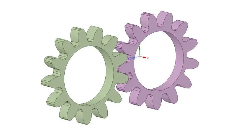
The geometry was imported from the model of spur gears provided.
Step 2: Material selection
The only parameter that separates the three cases is the material of the spur gears. The default material selected in ansys engineering data is structural steel. For case-1 (i.e. Cast Iron), the material has ti be added from data sources. Structural steel material can be suppressed, this will make cast iron as the default material for the spur gears in case-1.
For case-2 (i.e. Cast Steel), new material can be created by clicking 'add new material' option in engineering data.
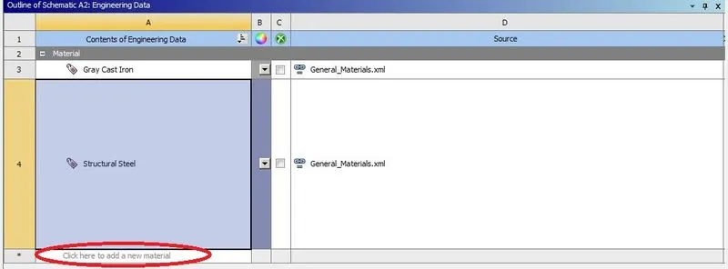
data for cases-2 and 3 was extracted from the data given above and material is created accordingly. Again, other materials except one under consideration are suppresssed so that default material is the material we're concerned with.
Step 3: Meshing
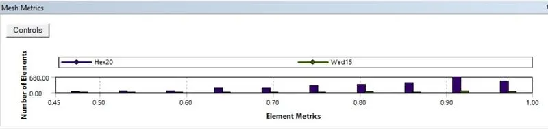
Meshing constraints have been consoidered as follows,
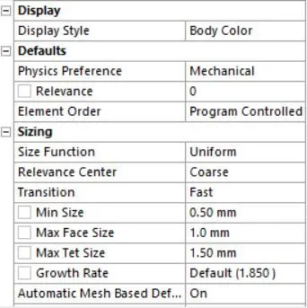
Mesh properties have been kept the same in all three cases in order to maintain parity between the cases. Mesh created is as such,
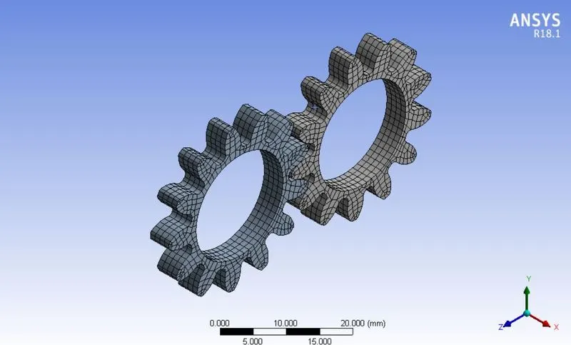
Step 4: Processing
Processing the model involves creation of connections, Joints, Bouindary conditions, Loads etc.
1. Creation of Connections:
Connections include creation of contacts as well as joints in this problem. By virtue of the model, Ansys considers the faces in contact as contact regions. However, during the course of simulation all faces of gear teeth will be contact regions and hence have to be considered.
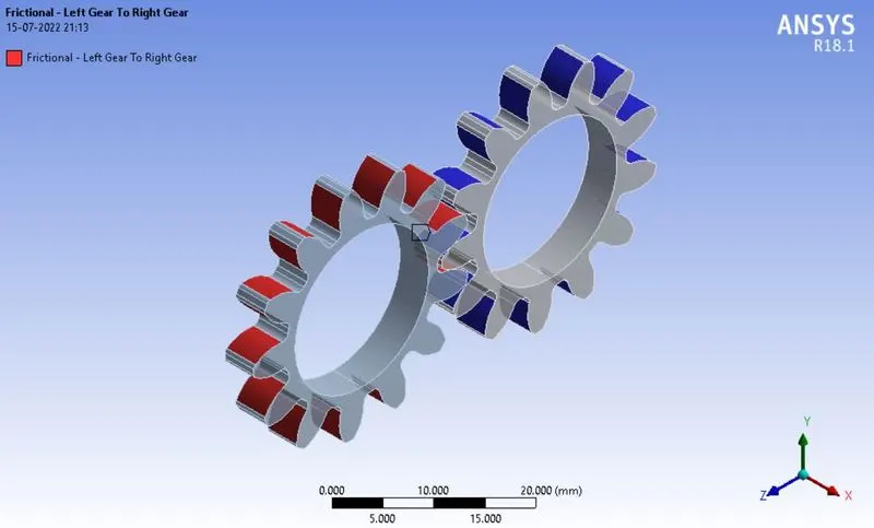
Since gears have 13 teeth each, all 26 faces of contact and target gear has to be selected. Target body is selected as such that the contact body is not allowed to penetrate the target body but target body is free to penetrate. In present case, since both bodies are under consideration either can be considered as target and contact bodies.
Connections are considered frictional and Adavanced lagrange formulation is considered for high stiffness and low penetration between gears.
Second part is creation of joints. Since both the gears are freee to rotate in z-direction, creation of revolute joint creates and axis for revolution of gears. Inner face of each gear is selected for creation of revolute joint.
2. Analysis settings:
Number of steps for convergence is increased from 1 to 6 so that we can observe stresses and strains at each step separately. The time step for iterations is set as,
- initial time step- 0.2
- minimum time step- 5E-2
- maximum time step- 0.5
large deflections are allowed so as to limit any false stiffness creeping into the model unkown. Auto time stepping is switched ON and steps controls are defined by time instead of substeps.
3. Joints load:
Now a joint load for the geometry is created. For right gear, Right clk>insert>joint load. Now DOF is defined as rotation in Z, Type of load as rotation and magnitude as tabular data. Now tabular data as 30, 60, 90, 120, 150, 180 deg is created. For left gear, DOF as rotation Z is defined , Load Type is set as moment and magnitude as tabular data. Now create tabular data as -10000N/mm.
Objective 2:
Comparison of Results
Step 5: Results and Post-Processing
The results for the simulation include of 4 parameters, i.e. Total Deformation, Equivalent Stress (Von-Mises), Equivalent Strain (Von-Mises) and Stress Intensity.
Stress Intensity is defined as the maximum value of the difference between the maximum and minimum principal stresses. Generally, stress intensity is twofold of the Maximum shear stress value.
a. Total Deformation:
Comparison of total deformation results of three case has been made here,
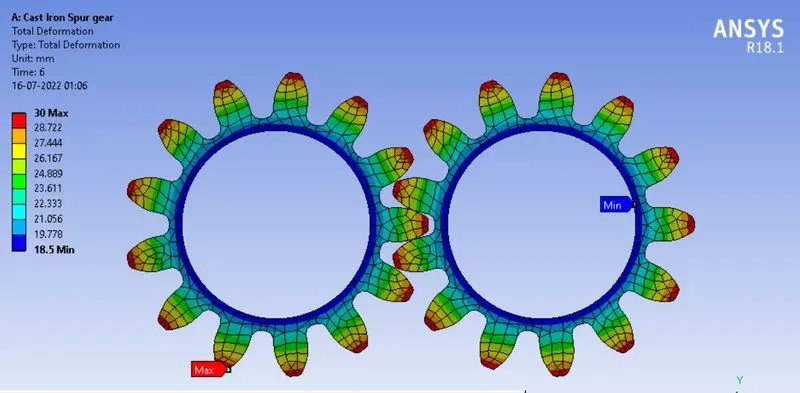
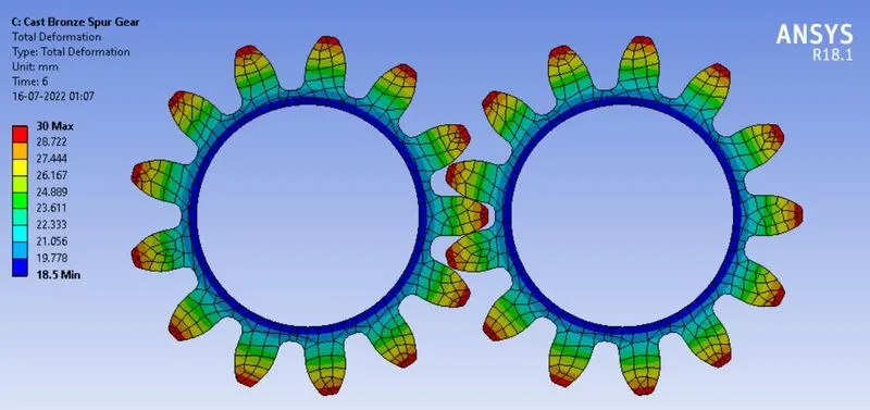
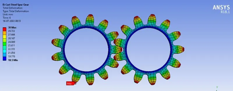
It can be observed that the value of max deformation in all the htree case is the same as 30mm.
b. Equivalent Stress
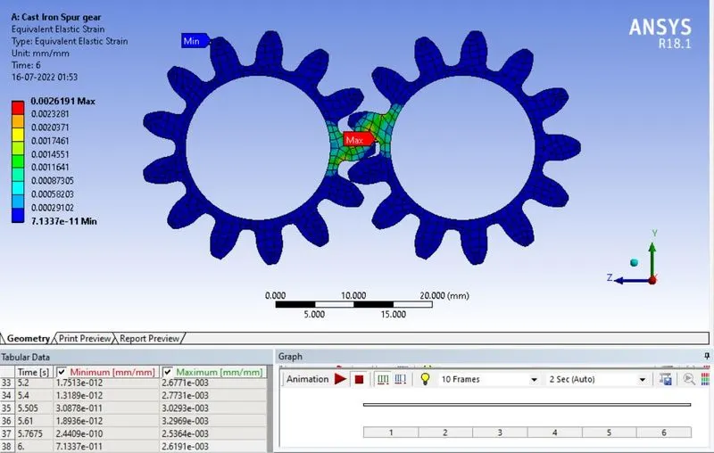
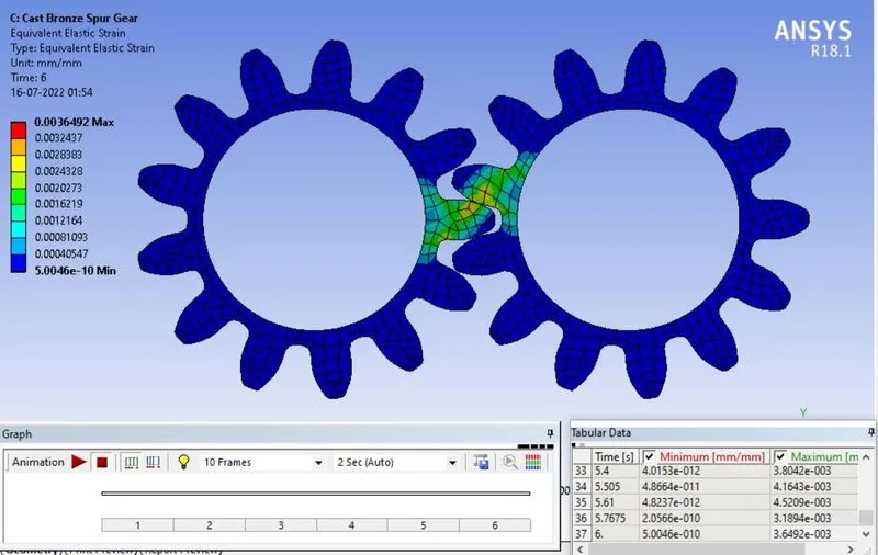
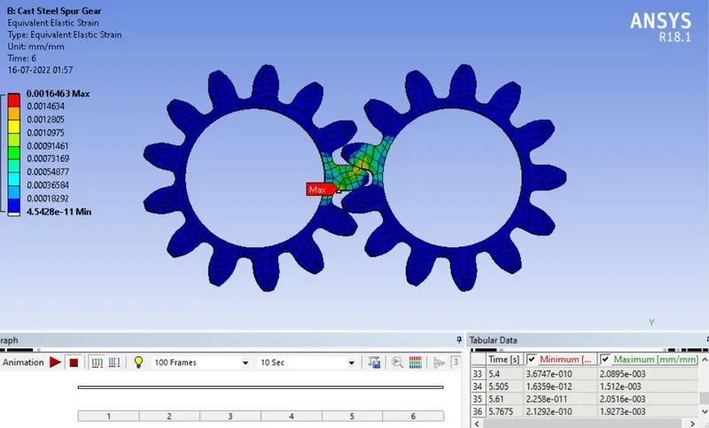
c. Equivalent Strain
d. Stress Intensity
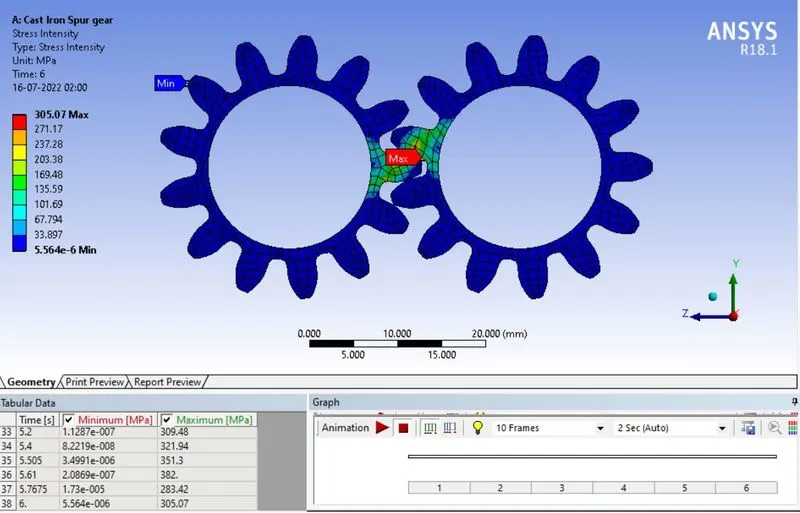
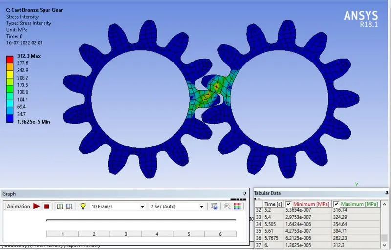
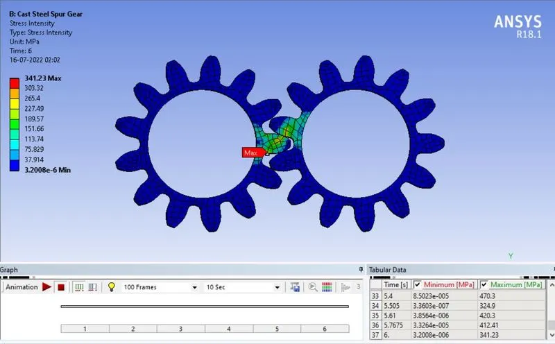
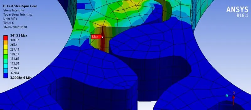
The Max stress intensity probe in the figure shows the location of possible failure.
Conclusion:
Conducting a statistical comparison of the results obtained from the simulation, we get the following table,
| Material | Max. Total Deformation (mm) | Von-Mises Stress (MPa) | Von-Mises Strain | Stress Intensity (MPa) |
| Cast Iron | 30 | 282.99 | 0.00262 | 305.07 |
| Cast Bronze | 30 | 286.87 | 0.00365 | 312.3 |
| Cast Steel | 30 | 331.71 | 0.00165 | 341.23 |
We can make the following observation,
- Total deformation in all three cases is almost the same.
- An ascending trend in value of stresses from cast iron to cast bronze to cast steel is evident. Equivalent stresses is the highest in cast steel and the lowest in cast iron.
- The stress intensity being the closest measure to gauge failure also gives a clear picture of viability of a material. The stress intensiy in cast iron material is the lowest making it least succeptible to failure.
- The Equivalent strain developed in cast iron is also moderate and not too high.
Based on these evidence, it must be recommended that cast iron material is the most favourable material to be used in manufacturing of Spur gears under the given conditions.