Week 1- Mixing Tee
AIM: To set up steady-state simulations to compare the mixing effectiveness when hot inlet temperature is 360C & the Cold inlet is at 190C.
- Case 1
- Short mixing tee with a hot inlet velocity of 3m/s.
- Momentum ratio of 2, 4.
- Case 2
- Long mixing tee with a hot inlet velocity of 3m/s.
- Momentum ratio of 2, 4.
INTRODUCTION:
This the simulation processing to know the output temperature of the fluid after mixing the the hot fluid and the cold fluid with the given temperatures of the hot and cold fluid. this kind of process is use to achieved to desired temperature of the output fluid from the mixing tee. this is mostly used in the air conditioners. by contolling the cold fluid velocity to get the desired temperature of the room.
PROCEDURE:
1. here i opened the ansys then i drag the ansys fluent to the work space then it show some popup like this
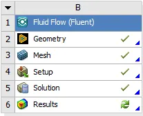
fig: main setup.
2. then i open the geometry part in the popup in that i imported the raw model into the spacecalim to edite the model.
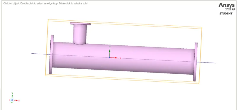
fig: raw model.
3. then i extracted the inner fluid volume to simulation on the fluid volume only. then i used option supresfor physic not use the simulation perpose.
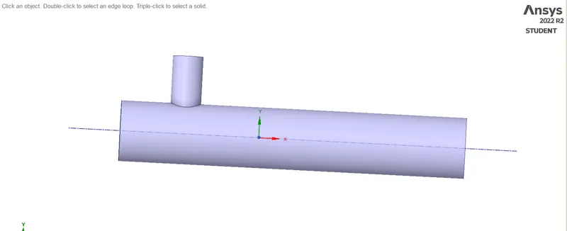
fig: fluid volume extraction.
4. then i went to the meshing part to made the mesh on the extracted volume. here i used the option in the meshing part to make the inflatuion layers and face sizing.
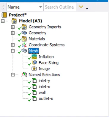
fig: meshing setup the made to the model.
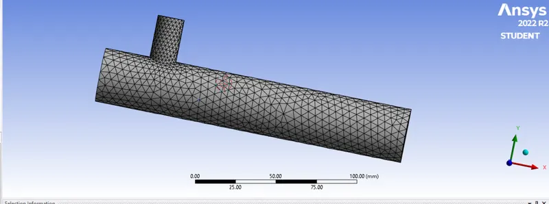
fig: mesh part
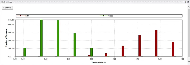
fig: element quality
here i have give the mesh element sizing is of the 5mm.
5. the i have given the name selection for the inlet x ,inlet y ,wall and outlet x for the geometry model. then i went to the solution setup part.
6. from the starting of geometry part to the setup part is same for all the cases the in the mixinng tee of short and long.
CASE 1 short tee
Short mixing tee with a hot inlet velocity of 3m/s.
Momentum ratio of 2
1.here i have given the energy equation on, K omega sst in the solver setup. then i gievn the cell conditions and the boundary conditions that are to set the inlet hot fluid and inlet cold fluid temperature that are 36 c and 19 c then i have inlet hot fluid velocity 3m/s and the cold fluid velocity 6 m/s. here i set the userdefined fluid to use the fluid in the simulation.
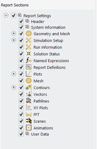
fig: sover setup.
2. then i have created the reports for the area weighted average and the standed deviation.
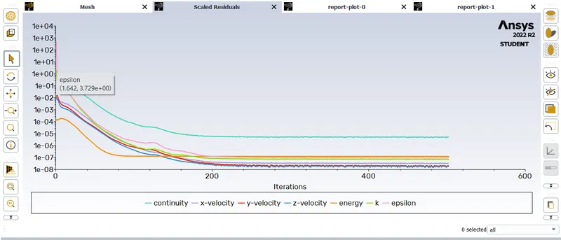
fig: residual plot.
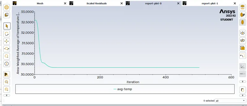
fig: avg temperature plot.
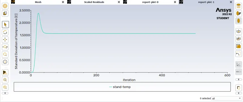
fig: standed deviation plot.
CASE 2 short tee
Short mixing tee with a hot inlet velocity of 3m/s.
Momentum ratio of 4
1.here i have given the energy equation on, K omega sst in the solver setup. then i gievn the cell conditions and the boundary conditions that are to set the inlet hot fluid and inlet cold fluid temperature that are 36 c and 19 c then i have inlet hot fluid velocity 3m/s and the cold fluid velocity 12 m/s. here i set the userdefined fluid to use the fluid in the simulation.
fig : solver setup.
2. then i have created the reports for the area weighted average and the standed deviation.
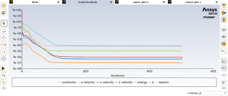
fig: Residual plot.
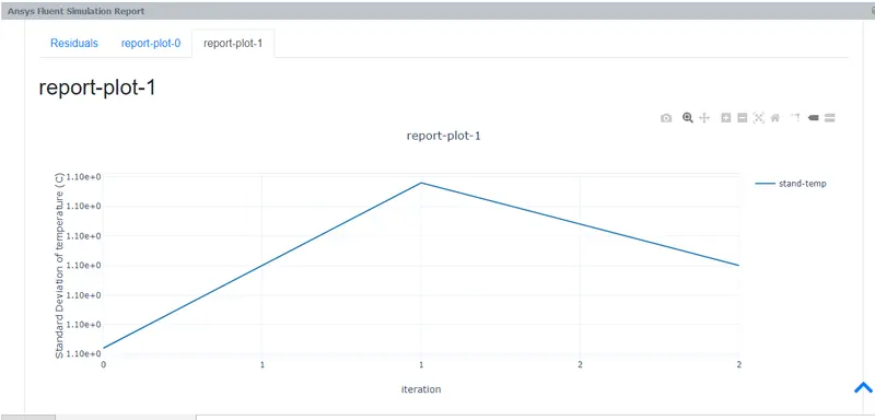
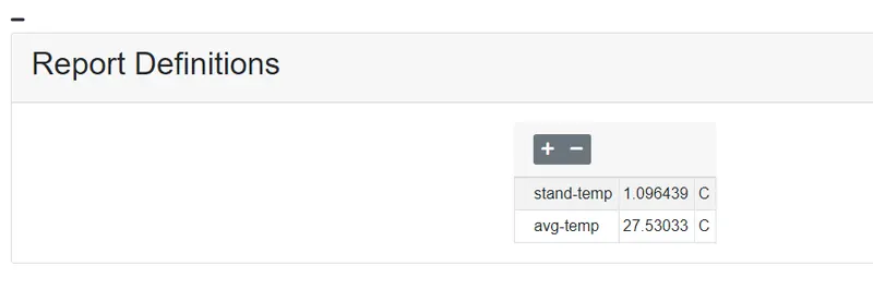
fig: standed temperature.
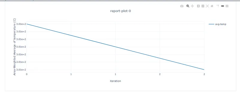
fig: avg temperature.
CASE 3 long tee
long mixing tee with a hot inlet velocity of 3m/s.
Momentum ratio of 2
1.here i have given the energy equation on, K omega sst in the solver setup. then i gievn the cell conditions and the boundary conditions that are to set the inlet hot fluid and inlet cold fluid temperature that are 36 c and 19 c then i have inlet hot fluid velocity 3m/s and the cold fluid velocity 6 m/s. here i set the userdefined fluid to use the fluid in the simulation.
2. then i have created the reports for the area weighted average and the standed deviation.
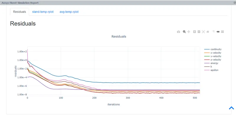
fig: Residual plot
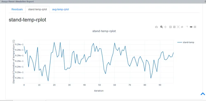
fig: standed deviation
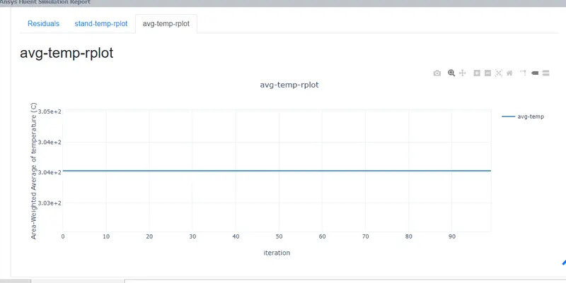
fig: avg temperature
CASE 4 long tee
long mixing tee with a hot inlet velocity of 3m/s.
Momentum ratio of 4
1.here i have given the energy equation on, K omega sst in the solver setup. then i gievn the cell conditions and the boundary conditions that are to set the inlet hot fluid and inlet cold fluid temperature that are 36 c and 19 c then i have inlet hot fluid velocity 3m/s and the cold fluid velocity 12 m/s. here i set the userdefined fluid to use the fluid in the simulation.
2. then i have created the reports for the area weighted average and the standed deviation.
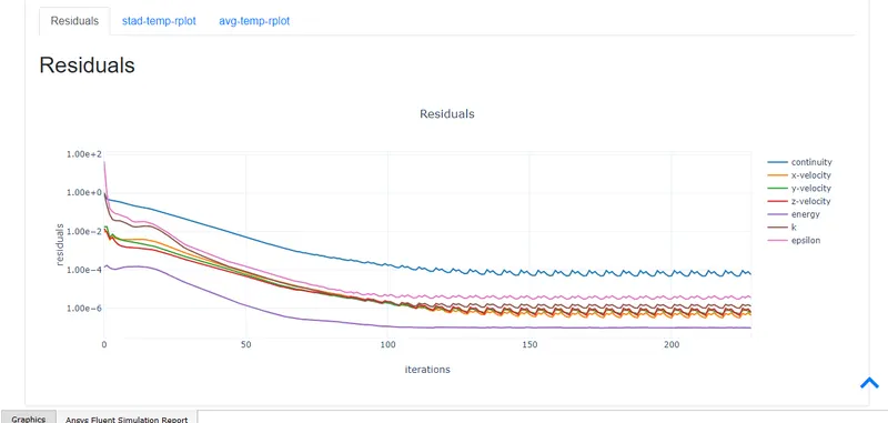
fig: Residual plot.
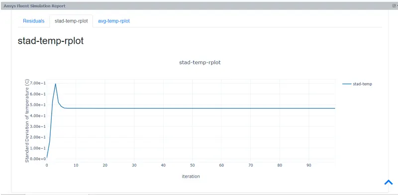
fig: standed deviation plot

fig: average temperature plot.
OUTPUT:
| s.no: | case | stand deviation at outlet | Avg temp at outlet 0c |
| 1. | short tee case 1 | 1.5699567 | 30.330835 |
| 2. | short tee case 2 | 1.0964383 | 27.530328 |
| 3. | long tee case 1 | 0.9290328 | 30.379087 |
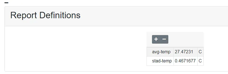
| 4. | long tee case 2 | 0.4671676 | 27.472314 |
ANALYTICAL METHOD:
MOMENTUM RATIO 2:
• Mass of hot fluid (mn) = rho*a*V₁ = 997*0.0009*3 = 2.69kg/s
• Mass of cold fluid (mc) = rho*a*Vc =997*0.0009* 6 = 1.35kg/s
Temperature of mixture (Tmixture) = (mn*Th - m c*T c )/(m c +m h )=30.319 0C = 303.319k
MOMENTUM RATIO 4:
• Mass of hot fluid (mn) = rho*a*V₁ =997*0.0009*3 = 2.69kg/s
• Mass of cold fluid (mc) = rho*a*Vc =997*0.0009* 12 = 2.3928kg/s
Temperature of mixture (Tmixture) = (mn*Th+ m c* T c )/ (mc + mh) = 27.99 0c = 300.99k
RESULT:
case 1 short tee
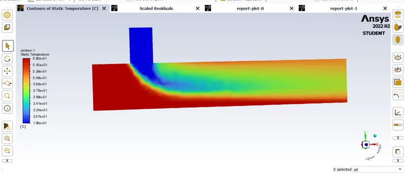
fig: temp contour
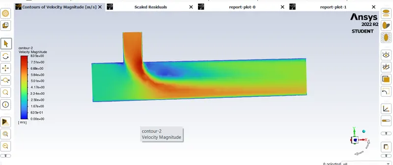
fig: velocity contour.
CASE 2 Short tee
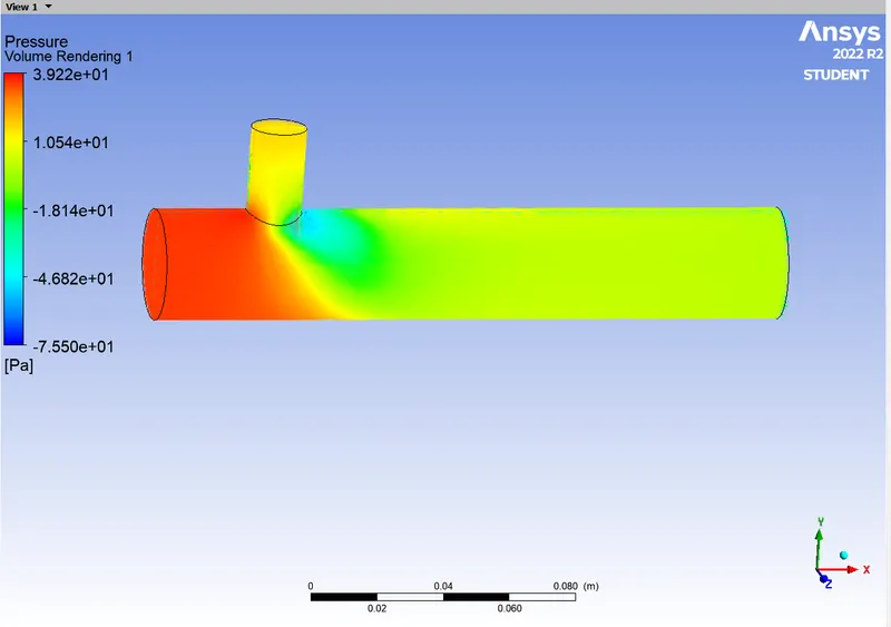
fig: pressure volume rendering
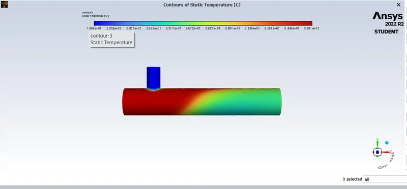
fig: temp contour.
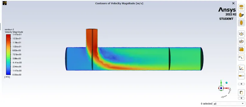
fig: velocity contour.
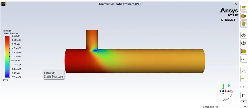
fig: pressure contour
CASE 3 long tee
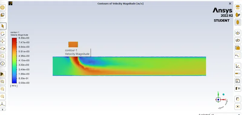
fig : velocity contour
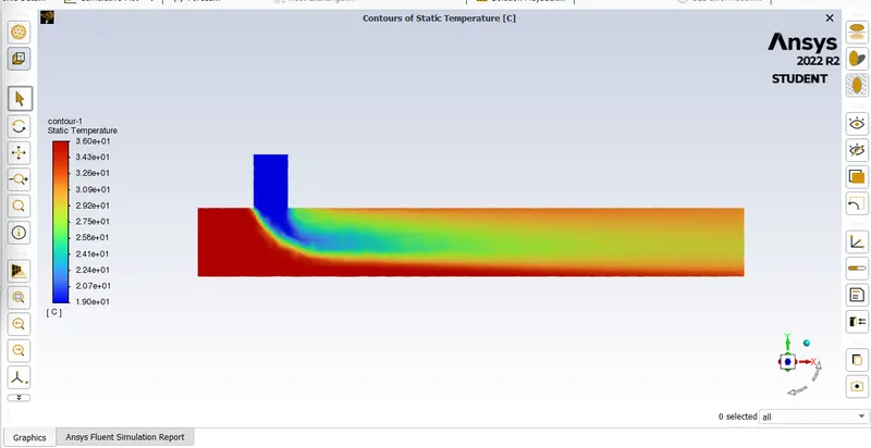
fig: temp contour
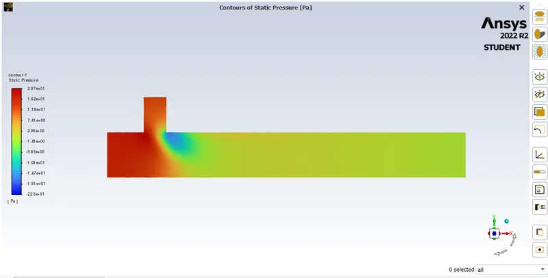
fig: pressure contour
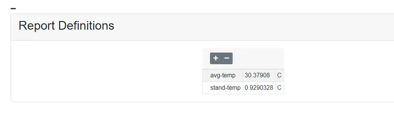
CASE 4 long tee
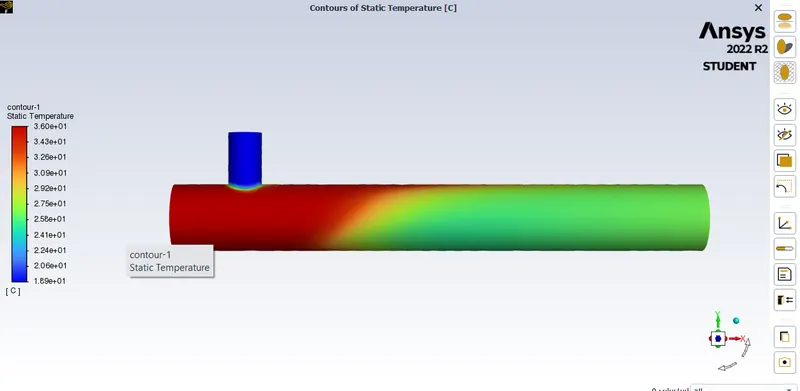
fig: temp contour
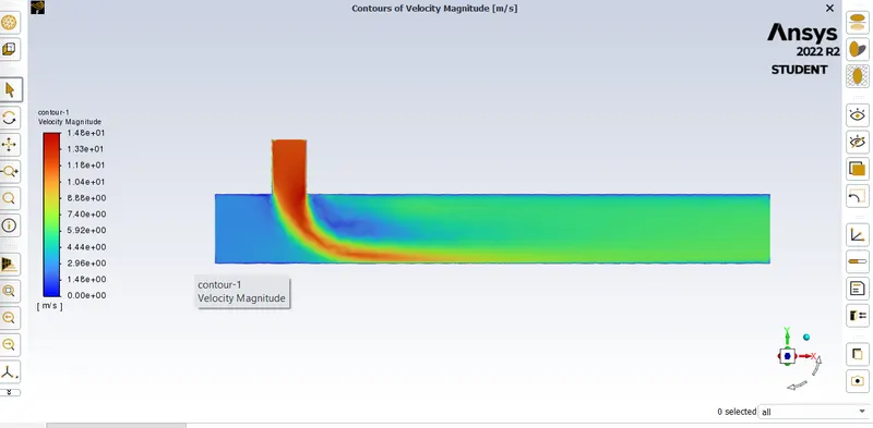
fig: velocity contour
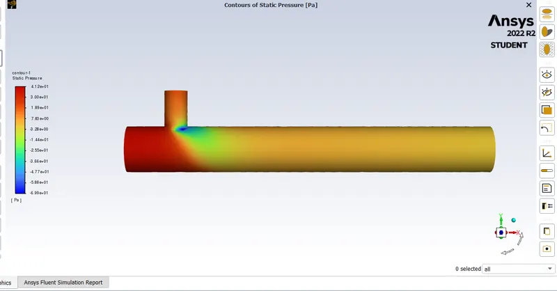
fig: pressure contour
CONCLUSION:
Here i conclued that the temperature is not much change between the long tee and the short tee. the length of the tee not changing the output temperature much. but the velocity of the inlet of the cold fluid will changing the ouput temperature of the fluid. the possion of the tee part is hot in the high velocity case.