Week 1 - Design Overview in Automotive Industry - Challenge 1
Aim:- To study the overview of the Automotive life cycle.
Q1. What are the 10 Stages of the Product life cycle of the automotive industry?
The 10 stages of the product life cycle in the Automotive Industry are,
- Concept Sketching
- Styling Class-A
- Feasibility Check
- Concept Validation
- New Product Design
- Development Stage
- Prototype Build
- Design Validation
- Pilot Production
- Mass Production
CONCEPT SKETCHING
- The purpose of concept sketching in the engineering domain is to provide communication at the early stages of the design which is a collection of visual cues sufficient to suggest the design to an informed observer.
- Freehand sketching is typically used with often a considerable number of iteration which generates visual thinking series of sketches.
STYLING CLASS-A
- In this phase, the initial concept sketch is validation for design aestheticism and CLASS-A Skin is developed through software such as Alias.
- 2D SKETCHES concept design get transformed into 3D using design software such as Autodesk Alias.
- The Class-A modelling process typically starts with a fully developed design, either as a scanned clay model or an Alias model
FEASIBILITY CHECK
- This phase kick starts the design engineering process the received Class A surface is validated for further stages of production feasibility.
- In this stage dose the market study of various components and also incorporated the feedback from the customers and stakeholders and updates that to the downstream processes.
CONCEPT VALIDATION
- In this stage phase, initial concept validation of the perceived model is done. Where all the design rules were validation and various studies such as visibility check, safety check, form drivers perspective were studied and all parts are started building around it.
NEW PRODUCT DESIGN
- The major work of product designers starts from this phase. After the concept validation stage, the designer starts developing CAD sketches of every component in the car.
- The main objective of the product designer is to incorporate all the inputs from the previous and ensure it is 100% manufacturable in the upcoming stages.
- the role of the designer is to do all the design work within the specified rules and design engineering standards of the organization.
DEVELOPMENT
- This stage forms as the bridge between the design team and the manufacturing team. The role of the development team is to ensure the design is feasible to manufacture and feasible to assemble.
- The development team works with the toolmakers, Mold and Fixtures and also with various outsourced vendors and stakeholders to kick start the manufacturing of the designed parts.
PROTO BUILD
- The next stage is to do a proto-build of the designed parts. A complete prototype is built to study the feasibility of the manufacturing process and materials used in the components.
DESIGN VALIDATION
- The design validation stage inspect any failures in the prototype like plastic deformation or dimensional instability and thy rectify the process ad materials
- This is the stage where the future design modification is frozen and only minor changes are allowed.
PILOT PRODUCTION
- The main role of the pilot production is to devise the lead time and manufacturing processes of various components and any defects in the production line will be identified and an assembly line is devised with the different stations.
MASS PRODUCTION
- After ensuring all the above stages the production of the components will be made live to mass production.
Q2. In which stages of the cycle is the Automotive designer’s involvement needed?
The three stages where the automotive designer involvement is needed are,
- Feasibility Check
- Concept Validation
- New Product Design
Q3. Which software is majorly used for Class A Design?
- The Autodesk Alias is the software used by the majority of OME to develop the Class-A surface.
Q4. Explain Feasibility check with Example.
A feasibility analysis enables the quick and easy evaluation of part and process feasibility. Even with the first design of part geometry, fundamental process capability should be checked for future series production, regardless of whether the CAD model has already been rounded.
At this point, there are often preliminary questions regarding whether the part can be manufactured as a single or double part, where exactly the part separation is planned, and whether the required material strength is achievable. Another issue that must be addressed at this stage is the later behaviour of the part in terms of crash, strength, stiffness or durability. The feasibility analysis allows early feedback on key quality criteria of the forming process.
This is the stage where carryover activities are done from the serious design version to reduce the lead time and also this is the stage where all Feedback and market studies involved from customers are incorporated into the automotive life cycle.
Feedback on feasibility which is delivered in an early, timely, reliable and comprehensible manner is crucial for balanced part design. The ever increasing demands on costs, quality and time must be taken into account. Problems which arise during the manufacturing of parts that have already been released for production are very expensive to correct – in terms of both time and costs. In addition, when later ad hoc measures are taken on parts, there is a risk of lower part efficiency and inconsistency in the quality of the finished part.
Q5. What are the stages of the Design Life cycle? Explain with examples?
The Stages of Design Life Cycle are,
- Concept Sketches
- Class A Creation
- Clay Modeling
- NPD CAD
CONCEPT SKETCHES
Concept sketches are sketches or diagrams that are concisely annotated with short statements that describe the processes, concepts, and interrelationships shown in the sketch.
It is usually done through pen and paper and some of the painting software. This will be used to generate the concept for preparing the model by incorporating various styles and information obtained through the stakeholders.
The below example shows the Electric SUV concept sketch by UM design.
This Electric SUV concept sketch by UM design is more aerodynamic with a smooth surface to reduce drag force. The more attractive look is given by the vampire's teeth.
CLASS-A SURFACE
In automotive design, a class A surface is any of a set of free form surfaces of high efficiency and quality. The minimum math requirement for Class A Surface is that the transition across the edge is a continuous curvature.
The Next Design life cycle is to create class A skin concept Sketches. This is done through 3D software and this embarks the head start
CLAY MODELING
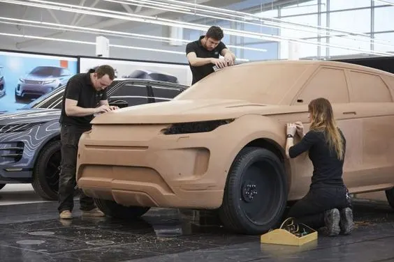
The Class A Surface is validated through Clay modelling and this gives the real visual representation of components that will be used to create input for the CAD Engineering to create 3D sketches of automotive components.
Clay Models are chiselled by hand to get the realistic experience by leading OEM and some of the interior compounds are done through machine
The role of this stage is to create a model as per the concept sketch and san using photometry to create a 3D CAD model.
The below picture shows the clay model of the New Range Rover Evoque Clay Modeling.
NPD DESIGN
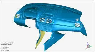
The final stage of the design cycle is performed by CAD Engineering who starts modelling the parts in the software with the design guidelines and ensure the functionality and feasibility of manufacturing and assembly. if that part violates or is not possible to manufacture then suitable alternatives are worked out by collaborating with the upstream and downstream processing teams.
Q6. What is concurrent engineering?
Concurrent engineering, also known as simultaneous engineering, is a method of designing and developing products, in which the different stages run simultaneously, rather than consecutively. It decreases product development time and also the time to market, leading to improved productivity and reduced costs.
Concurrent Engineering is a long term business strategy, with long term benefits to a business. Though initial implementation can be challenging, the competitive advantage means it is beneficial in the long term. It removes the need to have multiple design reworks, by creating an environment for designing a product right the first time around.
A significant part of the concurrent design method is that the individual engineer is given much more say in the overall design process due to the collaborative nature of concurrent engineering. Giving the designer ownership is claimed to improve the productivity of the employee and quality of the product, based on the assumption that people who are given a sense of gratification and ownership over their work tend to work harder and design a more robust product, as opposed to an employee that is assigned a task with little say in the general process.
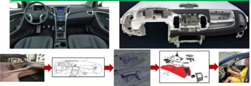
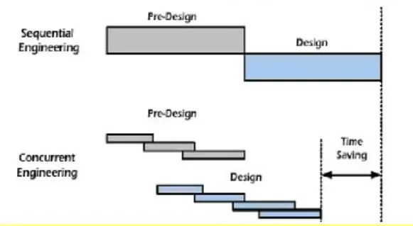
Staring from Clay Modeling to product style to concept sections to surface creations style then tooling and assembly with crash test checking, All done simultaneously.
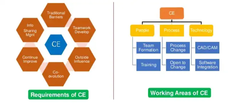
Requirements os Concurrent Engineering and Working Area of Concurrent Engineering
Q7. What is clay modelling? Explain its significance in Automotive Design.
Modelling clay is a flexible material that can be moulded in a variety of ways and maybe very long-lasting, in the case of hardening clays. Several materials can be used to make modelling clay and some products do not contain true clays, but are workable and behave like clay. These products are used by crafters, artists, and technical designers who may have reason to make clay models.
A clay model is a 3D sculpture that allows the designer to search for the desired surfaces directly on the model. Using sketches, tapes and CAD information, the modeller and the designer are working together to create a new design.
How do you make a clay model car?
Use coloured clay or paint to customize your car when finished. Form two balls of clay. Roll the large ball into an oblong shape like a sausage, as shown. Flatten one side of the sausage shape by pressing it against your flat workspace. Lay the sausage shape flat side down on your workspace.
Steps to make a clay model:
Step 1:- Print the Photos.
Step 2:- Cut Wood to size.
Step 3:- Glue prints to the Wood Pieces
Step 4:- Cut out Model.
Step 5:- Sand off any shreds Produced.
Step 6:- Glue two halves together.
Step 7:- Use a belt sander to Form and Smooth Shapes.
Step 8:- Print Cars with matching colours.
In auto or car detailing, there is a procedure referred to as “claying.” Traditionally, the claying process utilizes a clay bar that’s comprised of a soft resin compound most commonly made from synthetic materials.
Clay Bar for Cars
A clay bar is an engineered resin compound that can be synthetic or natural – although most manufacturers use synthetic versions. A somewhat elastic product, the elasticity gives the detailing clay great durability as it is repeatably rolled, flattened, and stretched over your car’s bodywork.
Modeling Clay is Heat Resistant.
polymer clay can burn if you do not bake it according to package instructions. Just like anything you would bake in the oven if you bake clay too hot for too long, it will burn.
Example shows the Ford Sculptors Design Car Using Clay,
The first clay models are designed at a 1:4 ratio
During the sculpting process
When the model is ready, the designer will arrive armed with blue tape that's used to mark out tweaked lines that the Sculptor will create.
Throughout the modelling process, the clay models are regularly scanned and examined as 3D models.
Eventually, after a long, two-year process, the car can be manufactured. Here's the result! The new Ford Mondeo.
Q8. Explain the Functional Requirement and functional reliability. Give examples on your own from the Automotive industry.
Functional Requirement
Functional requirements define what a software system should do. It defines a function of a software system or its module. Functionality is measured as a set of inputs to the system under test to the output from the system.
Functional requirement implementation in a system is planned in the System Design phase whereas, in the case of Non-functional requirements, it is planned in the System Architecture document. The functional requirement supports generating the non-functional requirements.
Types of Functional Requirements:-
- Interoperability:- Requirement describes whether a software system is interoperable across different systems
- Security:- The functional requirement describes the security aspect of software requirements.
- Accuracy:- Accuracy defines data entered into the system as correctly calculated and used by the system and that the output is correct.
- Compliance:- Compliance functional requirements validate that the developed system is compliant with Industrial standards.
Example: Take an example of the Infotainment systems project. The user enables Bluetooth here from HMI and checks whether Bluetooth is enabled or not. other Bluetooth services get enabled (from grey to bold) when the user enables Bluetooth. So, functional requirements talk about a particular system outcome when a task is performed on them by the user. On the other hand, the non-functional requirement gives the overall behaviour of the system or its component and not on function.
Non-Functional Requirements
The non-functional requirement says about “what a system should be” rather than “what a system should do” (functional requirement). They are mostly derived from functional requirements based on input from the customer and other stakeholders. Non-functional requirement implementation details are documented in the System Architecture document.
Types of Non-functional requirements
- performance
- Usability
- Maintainability
- Reliability
- Portability
- Supportability
- Adaptability
Functional Reliability
Functional reliability is one of the types of Non-Functional requirements. Reliability is another aspect of availability. This quality attribute emphasizes the availability of a system under certain conditions. It is measured as MTBF just like maintainability.
Example: Mutually exclusive features like rearview camera and Trailer in ADAS surround-view camera system should reliably work in the system without any interference with each other. When a user calls up the Trailer feature, the rearview should not interfere and vice versa as both features access the rear camera of the car.
Q9. What are DFM and DFA? Explain with examples on your own.
Design for Manufacturing (DFM)
Also commonly referred to as Design for Manufacturability concentrates on minimizing the complexity of manufacturing process operations by:
- Determining the cost of fabricating individual components
- Reducing machined component features to control production costs, increase quality and assembly time efficiencies, and improve DfA outcomes
Example: If you design a product’s case with variations in its walls’ thickness, the mould will have to be built accordingly; this will most likely result in faulty cases coming out of the mould, which will lead to re-work and an increase in costs.
Design for Assembly (DFA)
Revolves around simplifying the product structure, focusing on:
- Reducing the number of required product parts, thereby making assembly more efficient%
- Increasing ease of assembly by using keyed parts or components that can only go together in a certain orientation
- Ensuring ease of handling during assembly by measuring part size, weight, ease of dispensing, fragility, and flexibility
Example: Imagine if you had removed those hard to handle parts from your design and instead you had used parts that are easy to grab for an operator.
Q10. Explain the Economic Factor of design with examples of your own.
Adhering to Functional Requirements, Reliability, DFM, DFA will reduce the cost of the part and improve the effectiveness. These factors are carefully considered in the design stages to avoid quality issues and rework.
Serviceability is also an important factor to be considered.
The Life cycle of the automotive not just ends with the production or sale with a customer. it runs till the life of the automobile on road. after-sales Team holds a high priority in providing serviceability to the automotive.
The frequent parts that are to be replaced in different service cycles should be easily accessible for the service engineers.
There will also be guidelines and procedure drawings made out to service engineers about the serviceability of various parts and how to detect the life cycle of the components.
The final economic consideration is Recyclability, there is a law in EU legislation that automakers are responsible for the recycling of car and components after their end of life and also the parts used has to be 90% Recyclable.
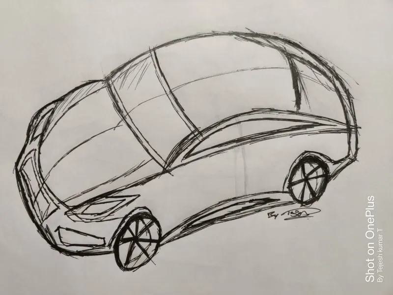
Q11. Draw an Automotive Freehand sketch. A sketch can be any automotive component or complete vehicle
A freehand sketch was done through lines, perspective
References:-
- https://www.autoform.com/en/glossary/feasibility-analysis/
- https://drawtodrive.com/um-design/electric-suv-concept-sketch-by-um-design
- http://nebula3dservices.com/class-a-surfacing/
- https://www.carbodydesign.com/image/75466/
- https://in.pinterest.com/pin/317363104991451378/
- https://www.concurrent-engineering.co.uk/what-is-concurrent-engineering
- https://www.slideshare.net/AdityaDeshpande50/concurrent-engineering-automotive-interiors-and-mnc-case-study/1
- https://www.digitalartsonline.co.uk/features/hacking-maker/how-ford-sculptors-design-cars-using-clay/
- https://www.seniorcare2share.com/why-is-clay-modeling-used-in-vehicle-design/
- https://www.softwaretestinghelp.com/functional-and-non-functional-requirements/
- https://titoma.com/blog/difference-dfm-dfa-dfma
- https://www.gmisolutions.com/blog/dfm-dfa-and-dfma