Week 2.1 - Air Standard Cycle
AIM:- To visualize P-V Diagram of Otto Cycle and to calculate thermal efficiency using MATLAB.
Objective:-
- To write a program to plot a P-V diagram of the Otto Cycle.
- To calculate Thermal Efficiency of Otto Cycle using MATLAB.
Theory:-
Air Standard Cycle
To carry out the analysis of the heat engine, the concept of air standard cycle was conceived. In these cycles, a certain mass of air is considered to be working in the thermodynamic cycle. The addition and rejection of heat are considered to take place with the external reservoir and ideally, all the processes are reversible. The internal combustion engines are considered to be working on the principle of air standard cycles. The two most commonly used air standard cycles are the Otto cycle and the Diesel cycle. The Otto cycle corresponds to four-stroke gasoline or petrol engines also called Spark Ignition (SI) engines. The Diesel cycle corresponds to four-stroke Diesel engines also called Compression Ignition (CI) engines.
The assumption made in Air Standard Cycle
- The combustion process is idealized by a constant-volume process (Sl cycle), a constant-pressure process (Cl cycle), or a combination of both (Cl Dual cycle).
- Exhaust blow down is approximated by a constant-volume process.
- All processes are considered reversible.
Otto Cycle
The Otto cycle is an air standard cycle that approximates the processes in petrol or diesel engines. It is based on constant volume heat addition (combustion) and heat rejection processes, and isentropic compression and expansion. The air-standard Otto cycle is the idealized cycle for spark-ignition internal combustion engines. This cycle is shown above on P–V and T-S diagrams. The spark-ignition engine is modeled with this Otto cycle. The actual P-V diagram for an engine has rounded corners because the processes of combustion take place at a finite rate. The Ideal Otto cycle has sharp corners because the ‘combustion’ is switched on and off instantaneously.
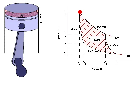
The Otto cycle 1 → 2 → 3 → 4 consists of the following four processes:
Process 1 → 2: Isentropic compression of air;
Process 2 → 3: Heat supply at constant volume;
Process 3 → 4: Isentropic expansion of air;
Process 4 → 1: Heat rejection at constant volume.
Formula's
- Swept Volume (Vs):- The volume swept by the piston during its motion is called swept volume.it is given as,
Vs = pi/4*d^2*l
where,
d = diameter or bore of the piston;
l = height of the piston. - Clearance Volume (Vc):- The space or volume which is left between the piston and top dead center of the cylinder during the combustion or exhaust stroke is called clearance volume.
Vc = Vs/(rc-1)
where,
rc = Compression Ratio of the cylinder. - Total Volume (Vt):- The Total volume of the cylinder is the summation of swept volume of the piston and the clearance volume.
Vt = Vs+Vc - Adiabatic Process:- The process which occurs without transferring heat or mass between a thermodynamic system and its surrounding is called an adiabatic process. This process obeys Boyle's law which is given as,
PVγ = Constant
where,
P = Pressure of the system;
V = Volume of the system;
γ = Value of the ratio of specific heats for the fluid. - Combined Gas Law:- This law is stated as the volume of a given amount of gas is proportional to the ratio of its temperature and pressure.
PT/T = Constant - Change of volume inside the engine combustion chamber is given by,
V/Vc = 1+1/2(rc−1)[R+1−cosθ−(R^2−sin^2θ)^1/2]
where,
V = Volume inside the cylinder when the piston is at an angle theta.
R = Ratio of length of connecting rod to crankpin radius(a).
Also crank pin radius(a) = Stroke length l/2. - Thermal Efficiency of Otto Cycle (h) is given as,
η=1−(1/rc^(γ−1))
Solution:-
Programming Language - MATLAB
Procedure/Steps
- Before writing the code, it is important to start with clear all, close all, clc.
clear all - removes data from the workspace,
close all - deletes the current figure or plot,
clc - clears all input and output from the command window.
- Define all the inputs values,
- Engine Geometry parameters,
Bore = 0.1 m
Stroke = 0.1 m
connecting rod (con_rod) = 0.15 m
Compression ratio (cr) = 12 - Swept Volume & Clearance Volume,
Swept Volume (v_swept) = (pi/4)*Bore²*Stroke
Clearance Volume (v_clearance) = v_swept/(cr-1) - Intial Pressure & Temperature
gamma = 1.4
p1 = 101325
t1 = 500
t3 = 2300
- Engine Geometry parameters,
- The swept volume and clearance volume are calculated using some relations and formulas.
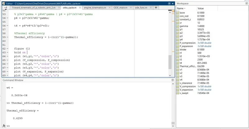
- Then by using the formula like p1v1^gamma = p2v2^gamma and ideal gas law p1v1/t1 = p2v2/v3. By using this equation we can find the other value of pressure, temp, and volume at different state points.
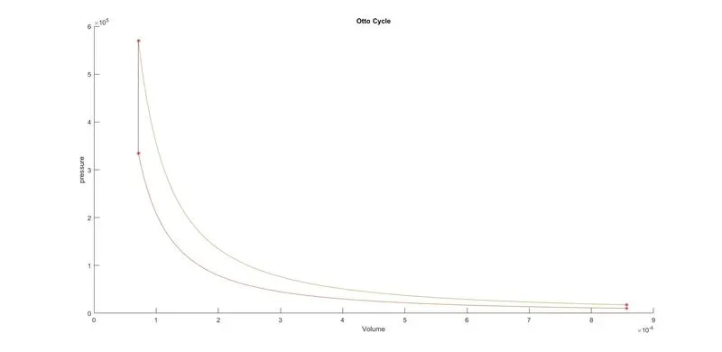
- For plotting, we are using the plot command and we get a PV diagram having four-point in it which Represents State points. after Executing the Program we get our required output.
- Now to achieve a set of solutions for every value of crank angle , a separate code is written in a new script.
Function
function [v] = engine_kinematics(bore,stroke,con_rod,cr,start_crank,end_crank) a = stroke/2 R = con_rod/a v_s = pi/4*bore^2*stroke; v_c = v_s/(cr-1); theta = linspace(0,180,180) term1 = 0.5*(cr-1); term2 = R+1-cosd(theta); term3 = (R^2 - sind(theta).^2).^0.5; v = (1+term1*(term2-term3)).*v_c; end - Here in this script, ‘function’ syntax is used which declares a function named “enging_kinematics” that accepts inputs “bore, stroke, con_rod, cr, start_crank, end_crank” and returns outputs in the “V” array.
- The value of crank angle ‘theta’ is calculated for 200 values between the initial angle and final angle.
- This function is called in the code and V_compression, P_compression, V_expansion, P_expansion are calculated with respect to the values of crank angle ‘theta’.
- The Thermal Efficiency is calculated by using the formula mentioned above.
- Finally, all state variable points are plotted along with the curves and the PV cycle is thus obtained.
MATLAB Coding:-
clear all
close all
clc

% Inputs
gamma = 1.4;
t3 = 2300;

%state variables
p1 = 10325;
t1 = 500

%Engine geometric parameters
bore = 0.1;
stroke = 0.1;
con_rod = 0.15;
cr = 12;

% claculating the swept volome & the clearance volome
v_swept = (pi/4)*bore^2*stroke;
v_clearance = v_swept/(cr-1);

v1 = v_swept + v_clearance;
v2 = v_clearance;


% state variable at ponit 2
% p2v2^gamma=p1v1^gamma
% p2 = p1*(v1/v2)^gamma = p1*cr^gamma
p2 = p1*cr^gamma;

%p1v1/t1 = p2v2/t2 | t2=p2*v2*t1/(p1*v1)
t2=p2*v2*t1/(p1*v1);

constant_c = p1.*v1.^gamma;
V_compression = engine_kinematics(0.1,0.1,0.15,12,0,180);
P_compression = constant_c./ V_compression.^gamma;


% state variable at point 3
v3 = v2;

% p3v3/t3 = p2v2/t2
p3 = p2 * (t3/t2);

constant_c = p3.*v3.^gamma;
V_expansion = engine_kinematics(0.1,0.1,0.15,12,0,180);
P_expansion = constant_c./ V_expansion.^gamma;

% state variable at point 4
v4 = v1

% p3v3^gamma = p4v4^gamma | p4 = p3*(v3/v4)^gamma
p4 = p3*(v3/v4)^gamma;

t4 = p4*v4*t3/(p3*v3);

%Thermal efficiency
Thermal_efficiency = 1-((cr)^(1-gamma));


figure (1)
hold on
plot (v1,p1,'*','color','r')
plot (V_compression, P_compression)
plot (v2,p2,'*','color','r')
plot (v3,p3,'*','color','r')
plot (V_expansion, P_expansion)
plot (v4,p4,'*','color','r')
plot ([v2,v3],[p2,p3])
plot ([v4,v1],[p4,p1])
xlabel('Volume')
ylabel('pressure')
title('Otto Cycle')
Output:-
Plot for P-V diagram
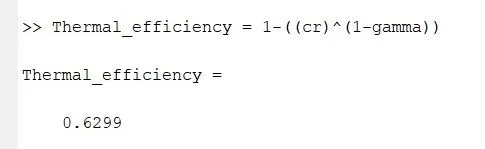
The Thermal Efficiency of the Engine.
Errors:-
Error#1:-Invalid expression or missing logical operation,
Solution #1:- The missing multiplication operator '*' is Corrected.
Conclusion:-
- The P-V diagram for all four processes has been plotted.
- The Thermal efficiency of the engine is 62.99% as noted, the thermal efficiency mainly depends on the compression ratio of the engine, so it can be concluded that an engine with a higher compression ratio will have high thermal efficiency.
Reference:-