Week 1: Channel flow simulation using CONVERGE CFD
AIM: Simulating channel flow using Converge CFD.
OBJECTIVE:
- To show velocity and pressure contours for all three base mesh sizes.
- To show plots for velocity,pressure,mass flow rate and total cell count for all three base mesh sizes.
INTRODUCTION
- It is a type of liquid flow within a conduit or in channel with a free surface.
- Flows in closed conduits or channels,like pipes or air ducts are entirely in contact with rigid boundaries.
- Most closed conduits in engineering applications are either circular or rectangular in cross-section.
- In this project ,we have taken rectangular cross-section channel with length,breadth and height as 0.1m,0.01m and 0.01m respectively.
PRE-PROCESSING AND MODELLING APPROACH
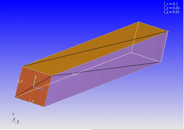
Fig.1
- The geometry is created by choosing create>shape>box.After that choosing the center and size of the box, the geometry is made.
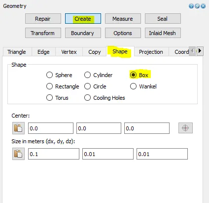
Fig.2
Fig.3
Fig.4
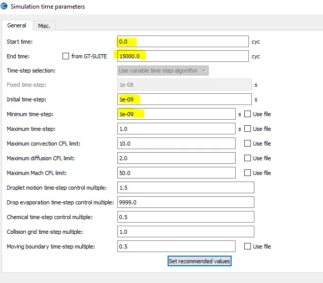
Fig.5
Fig.6
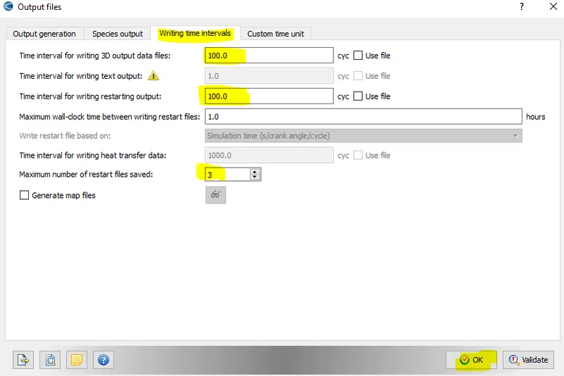
Fig.7
- Writing 3D output data files at time interval of 100 cycles. Total cycle is taken for 15000, so total number of output data files is 150.
- Again there are 3 number of restart files saved.
- For running the simulation either we can opt for cygwin or converge post processing.
- For running the simulation in CYGWIN, first of all we should navigate to folder where all the input files are exported.Then we need to run the command as
mpiexec.exe -n 4 "path" path = to call executable - converge-intelmpi.exe
The path includes : "C:\program files\convergent-science\converge\bin\converge-intelmpi.exe" restricted </dev/null> logfile &
Here the ampersand denotes that the simulation run at the backend.
For post-processing
$ mpiexec.exe -n 4 post_convert__30_msmpi_64.exe - This need to be copied in the output folder.
In order to view the simulation ongoing process, we need to run command as $ tail -10 logfile, it will show the last 10 lines of simulation status.
RESULTS
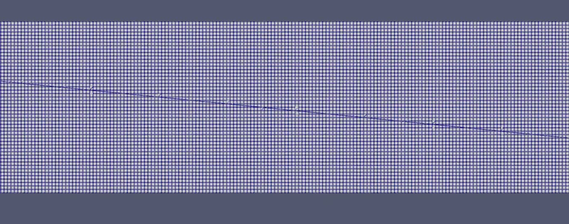
Mesh size of 0.2mm
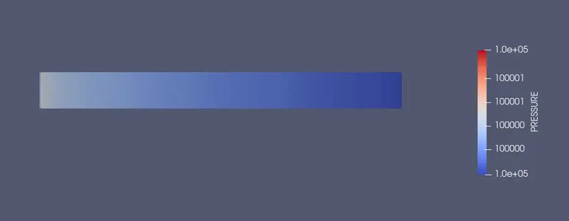
Pressure contour (mesh size 0.2mm)
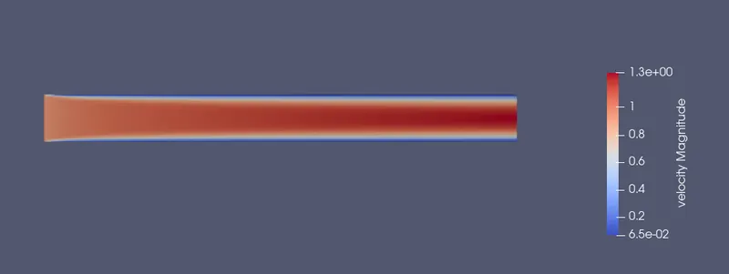
Velocity Contour (mesh size 0.2mm)
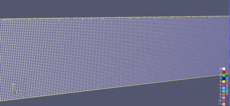
mesh size =0.15mm
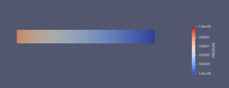
Pressure Contour (mesh size 0.15mm)
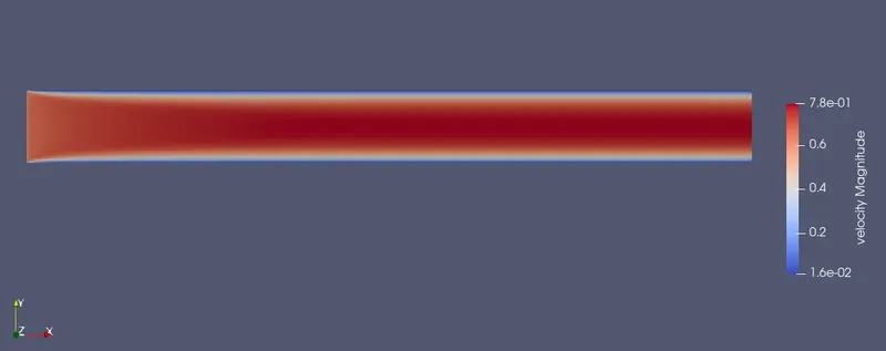
Velocity Contour (mesh size 0.15mm)
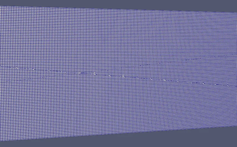
Mesh size 0.12mm
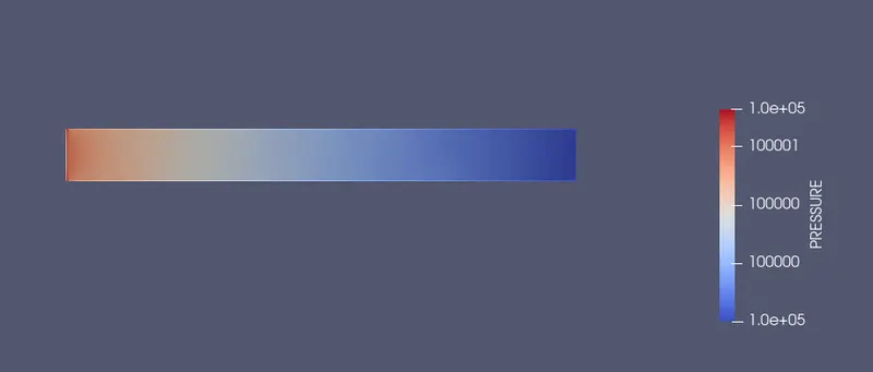
Pressure Contour (mesh size 0.12mm)
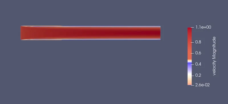
Velocity Contour (mesh size 0.12mm)
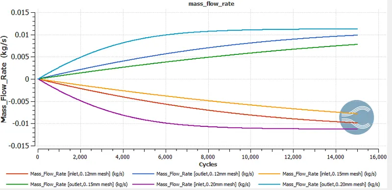
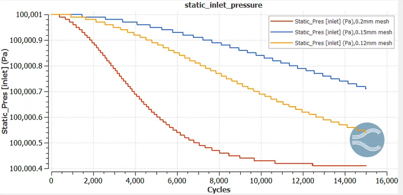
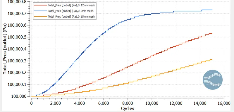
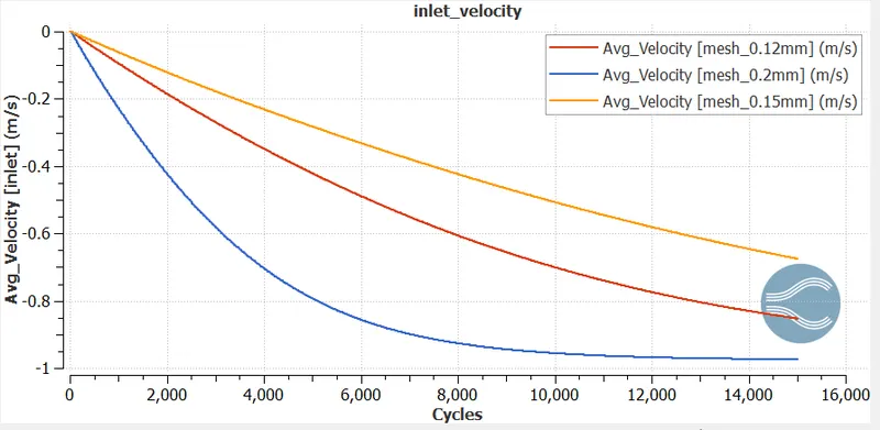
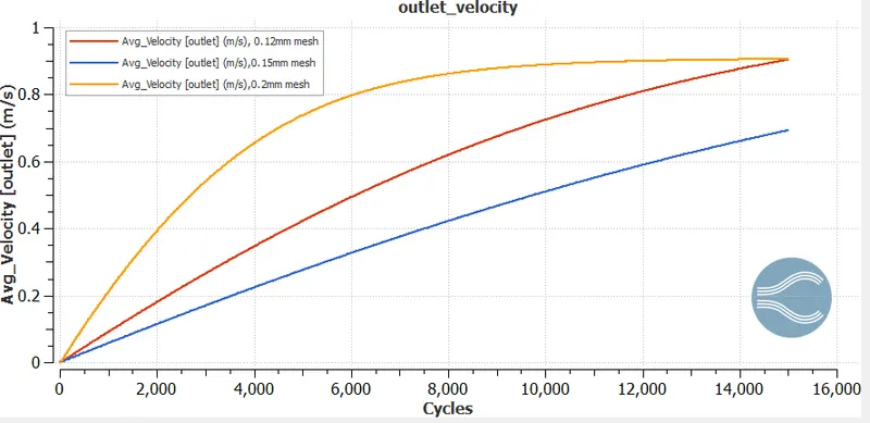
- If we look at this graph, at a particular cycle the value of avg. velocity magnitude for outlet is showing maximum for 0.2mm mesh size.
- The minimum velocity is seen for mesh size 0.15mm and intermediate value is for 0.12mm mesh size.
- The 0.12mm mesh size is showing near to accurate result as the grid is fine enough than other mesh sizes.
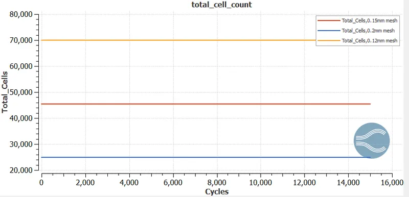
- Here the cell count is maximum for 0.12mm mesh size than other mesh sizes counting as 70,000,45000 and 25000 respectively.
- You-tube animation link for mesh size 0.20mm
- You-tube animation link for mesh size 0.0.15mm
- You-tube animation link for mesh size 0.12mm
CONCLUSION
- The mesh size 0.12mm shows the intermediate values of velocity,pressure and mass flow rate.
- As the mesh element( cell count) increases ,the simulation time increases as compared to other mesh element.