Week 1 Challenge
- AIM: To create a new project and name the project appropriately.
TOOLS REQUIRED:
- File menu
- Template
PROCEDURE:
a)Click on the file menu.
b)Click on new and select project.
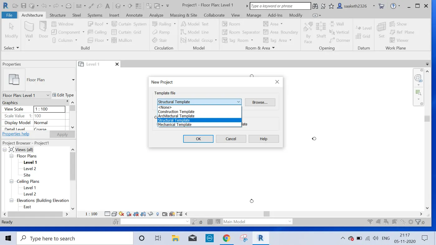
c)Now we can see options to select different types of template.
Select structural template and click ok.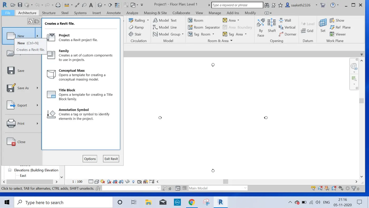
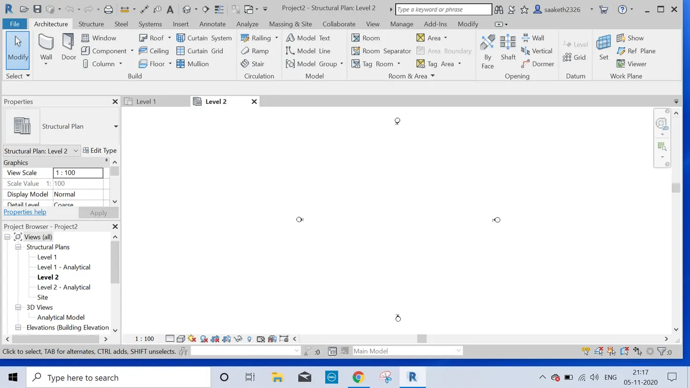
RESULT:
Required project is created.
2.
AIM: To save the new project file and to close and open using icons from file tool bar.
TOOLS REQUIRED:
- File menu
- Save as icon
- Close icon
PROCEDURE:
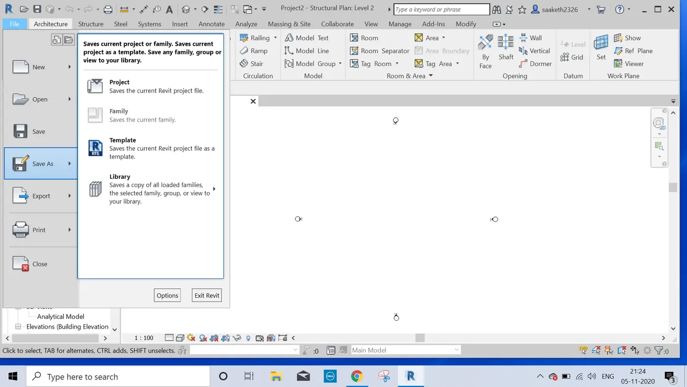
- Click on the file menu.
- Click save as option and click project in save as option.
- Name the project.
- Using the close toolbar close the project.
- Now by using open toolbar we can open our created project file.
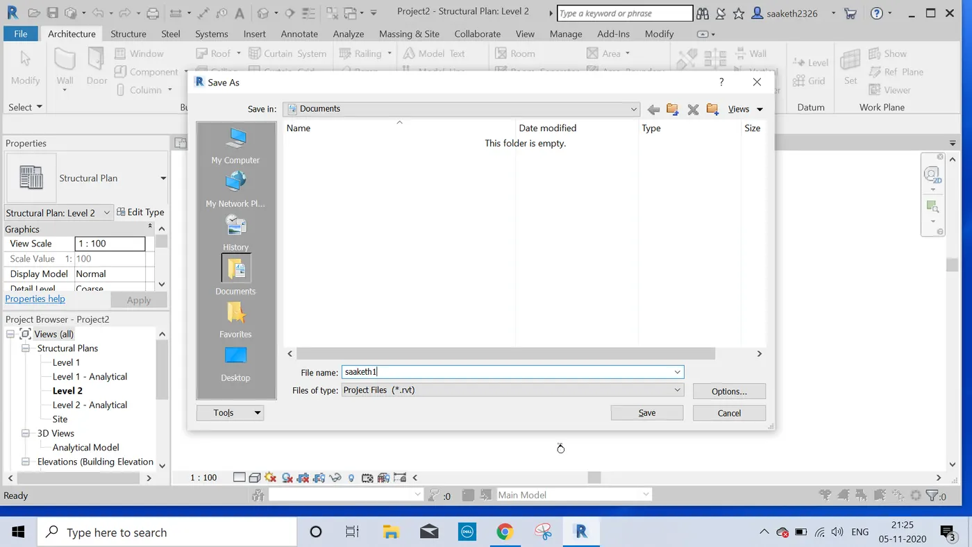
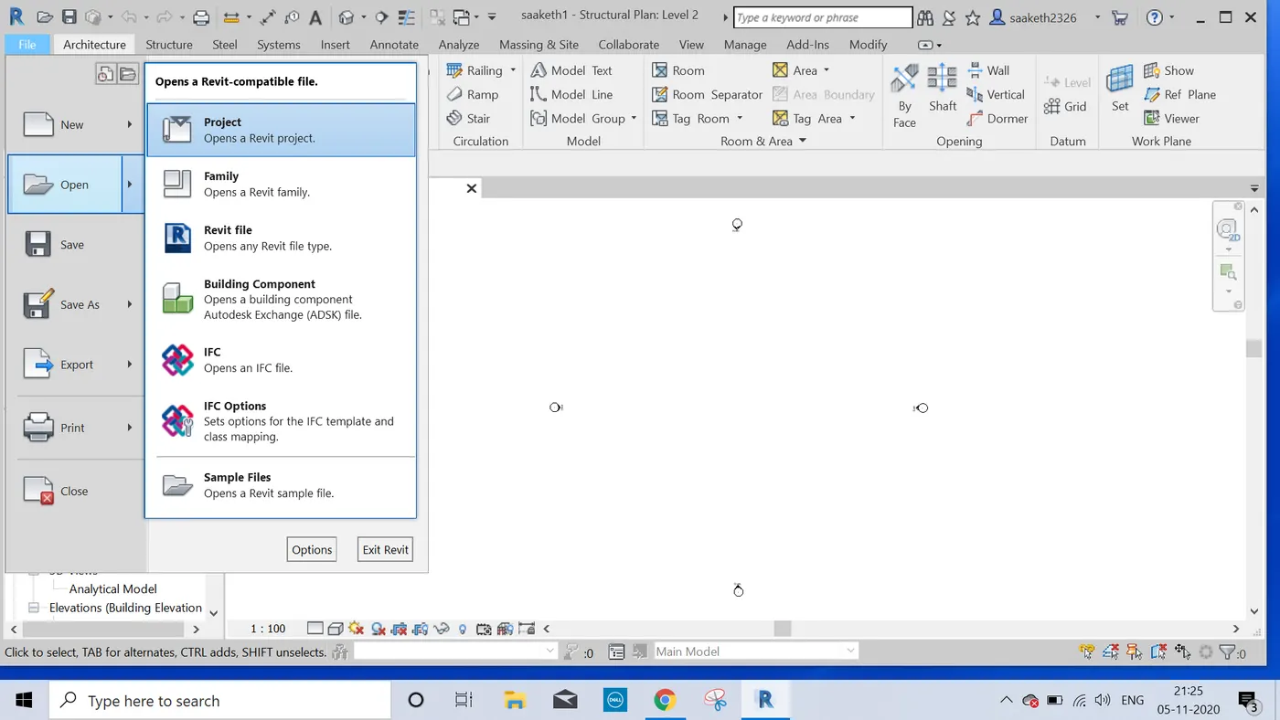
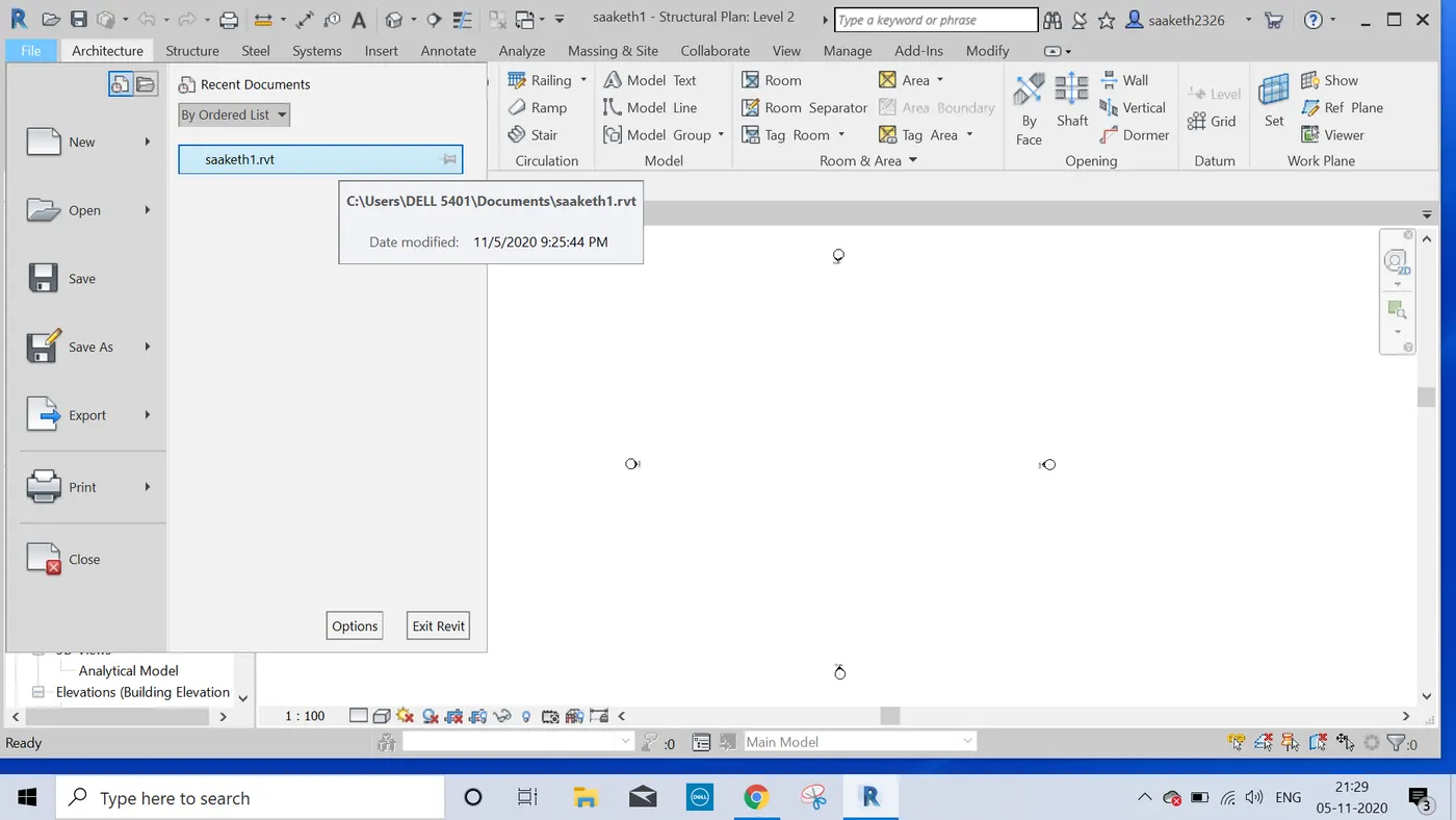 RESULT:
The saved project is closed and opened using icons in file toolbar.
3.
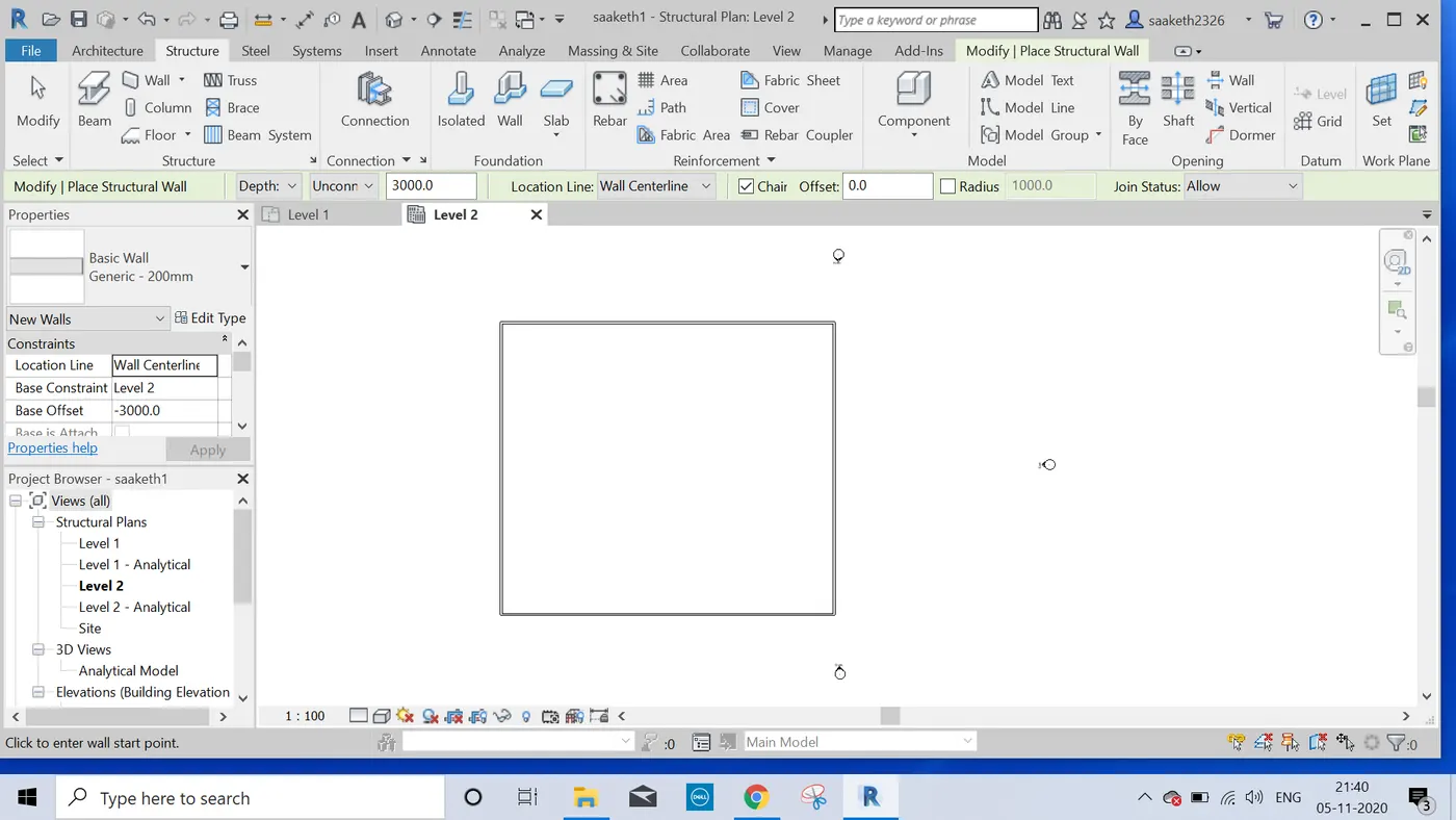
AIM: To familiarize with options to draw a wall and to create a rectangular layout of walls of about 40’ X 35’.
TOOLS REQUIRED:
- Architecture toolbar
- Wall
- template
PROCEDURE:
- Click on architecture tab.
- Select wall to create non-structural wall.
- Click architectural wall and place cursor on the model space.
- Now create a wall of dimensions 40’ X 35’.
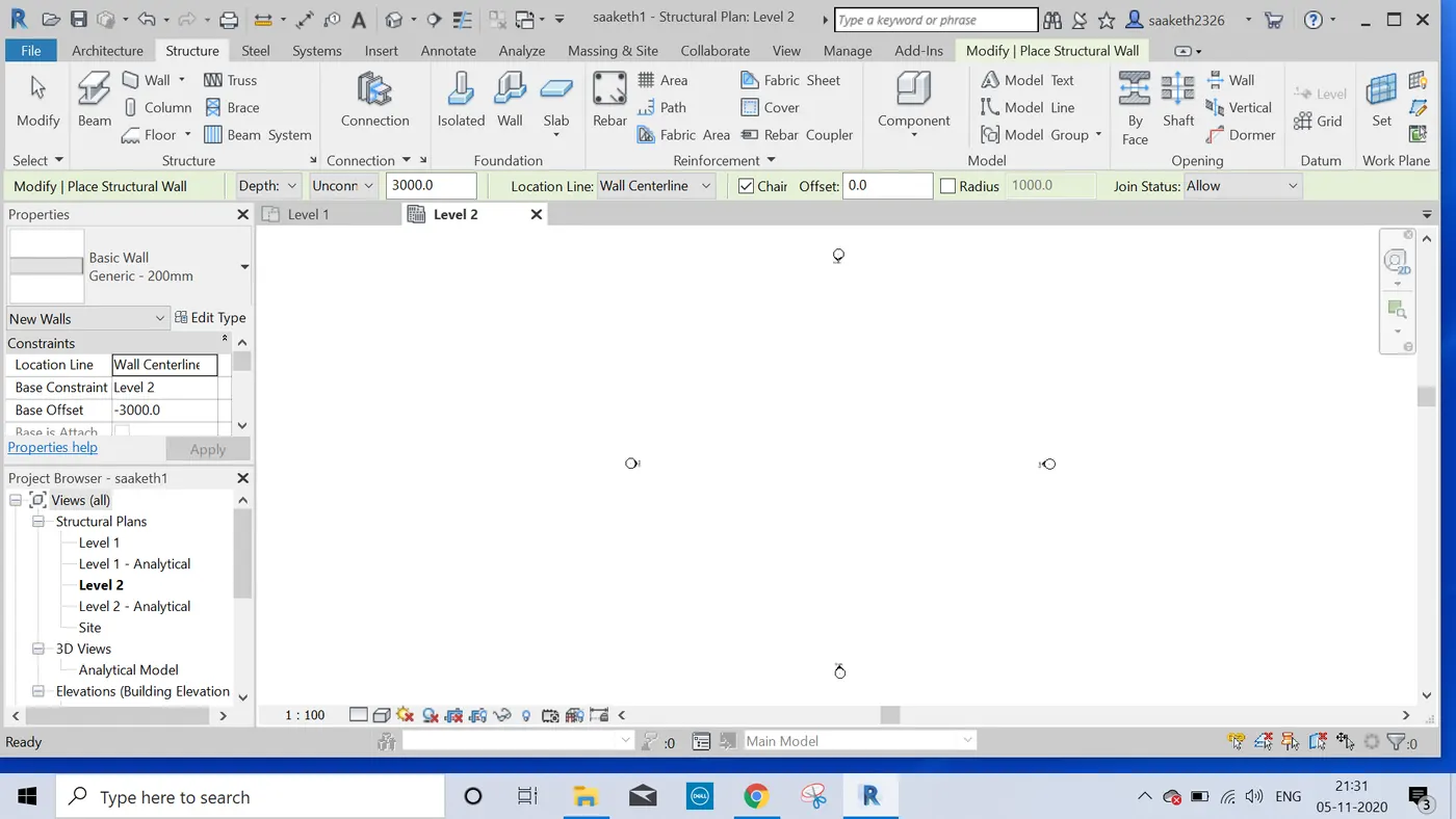
 RESULT:
Required wall of dimensions 40’ X35’ is created.
- AIM: To add dimensions to the layout with the help of aligned option.
TOOLS REQUIRED:
- Annotate toolbar
- Aligned option
PROCEDURE:
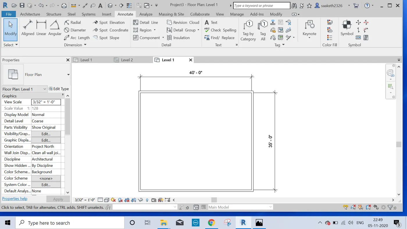
- Select annotate toolbar and click aligned option.
- Select from one end of wall to other end.
- Do the same with other two walls.
- We can get dimensions of rectangular layout.
RESULT:
Dimensions of the walls is known by using aligned option.
- AIM: To use properties browser to switch to different wall types.
TOOLS REQUIRED:
- File
- Properties
- Different types of wall
PROCEDURE:
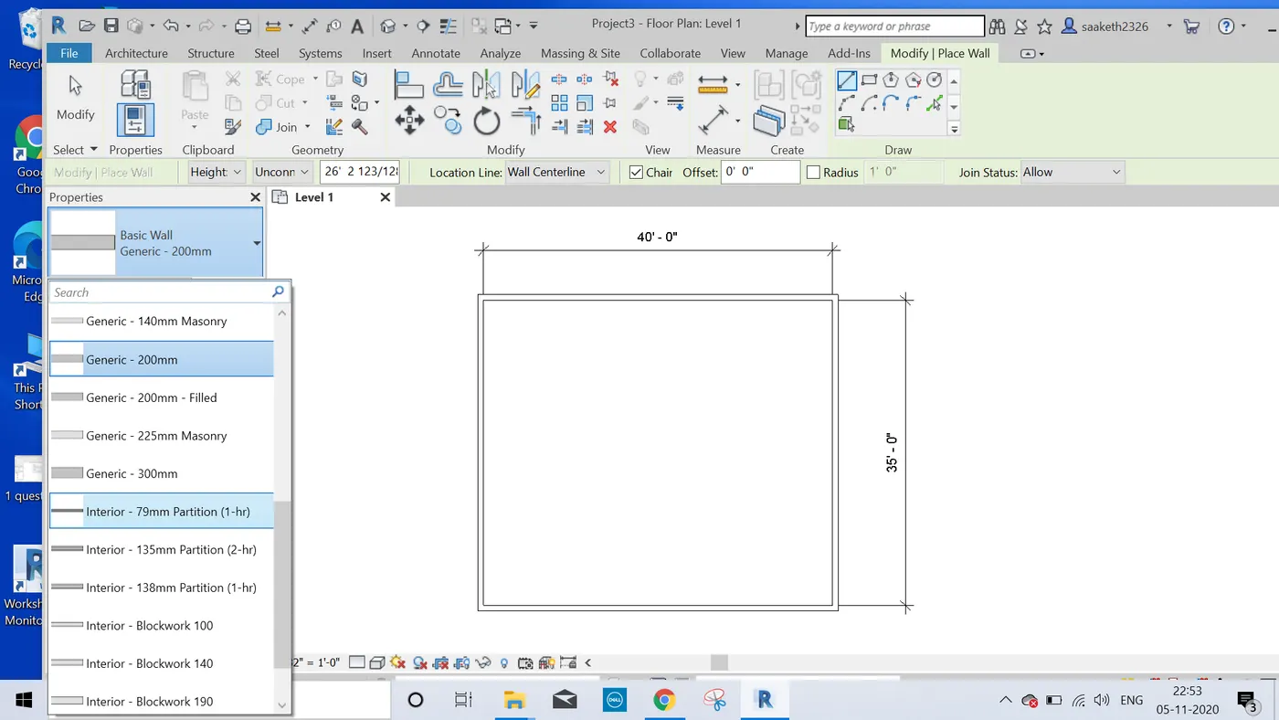
- Select wall in architecture toolbar.
- Click on properties.
- Select on the wall type. We can see different types of walls.
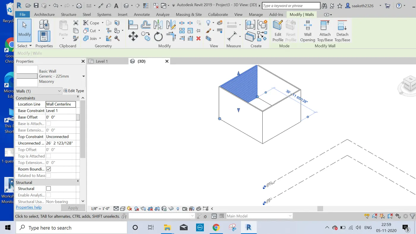
- Select required type of wall.
RESULT:
In this way different types of walls can be switched by using properties browser.
- AIM: To create 3D view and to save the view with appropriate name.
TOOLS REQUIRED:
- View toolbar
- 3D view option
- Save as
PROCEDURE:
- Open the rectangular layout that is previously created.
- Click on the view toolbar.
- In the view toolbar click on the 3D option. Now we can get 3D view.
- Now click save as option and save it with appropriate name.
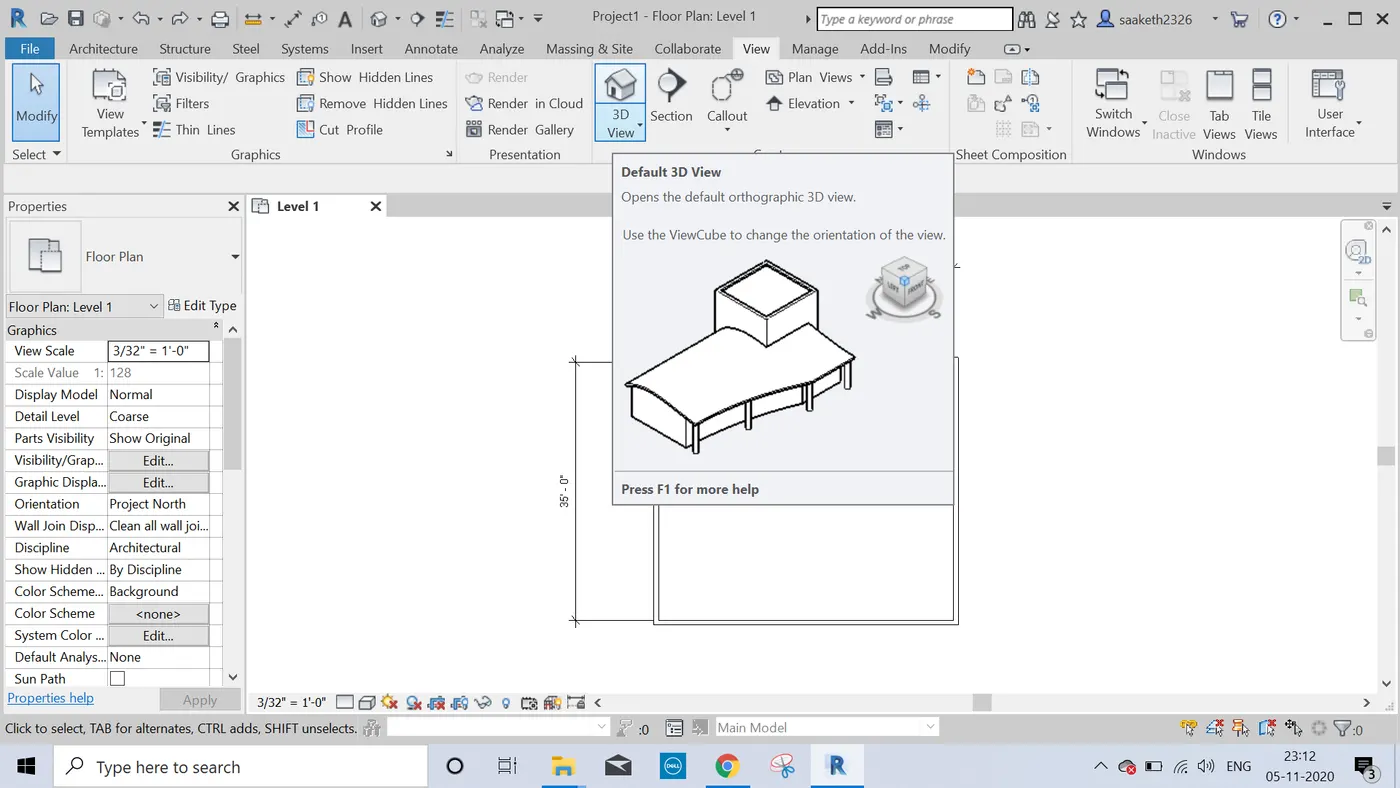
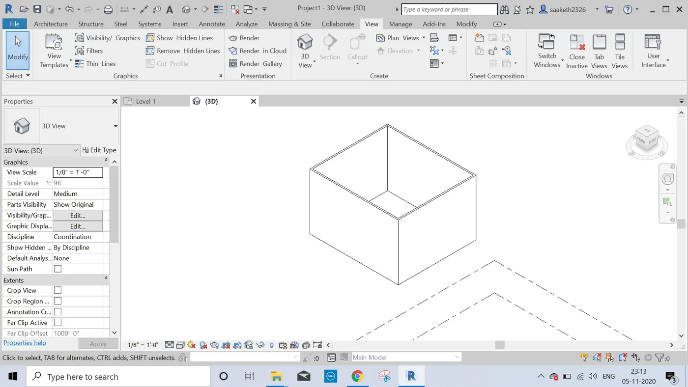
RESULT:
3D view is created and saved with appropriate name.
- AIM: To navigate through the 3D model using view cube and to orbit through the model layout.
TOOLS REQUIRED:
- View toolbar
- 3D view
- View cube
PROCEDURE:
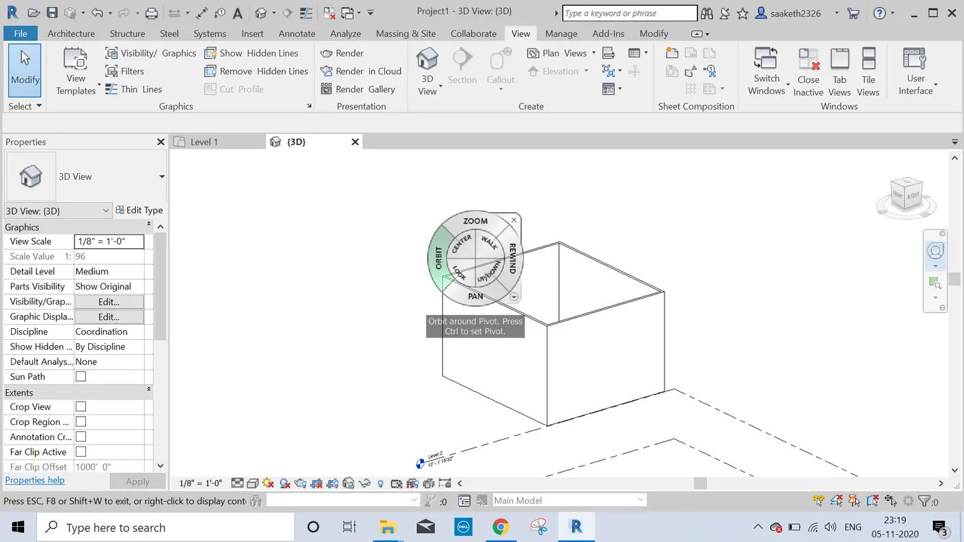
- Click view tool bar and click on 3D view option.
- Now we can see view cube click on it we can see different views of the 3D layout.
- In options we can see orbit option click on it.
- By using orbit option the layout can be navigated in 360 degrees.
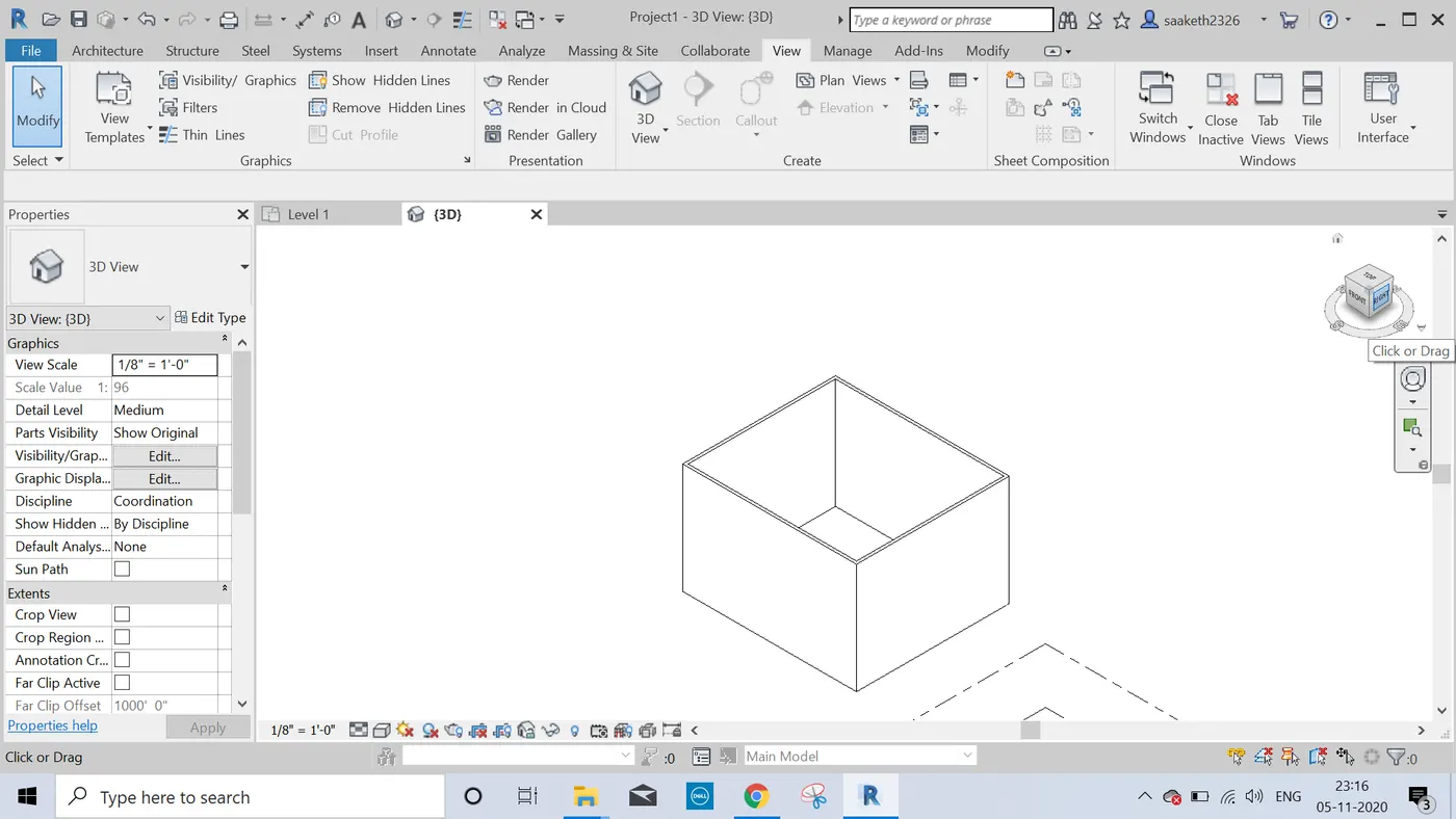
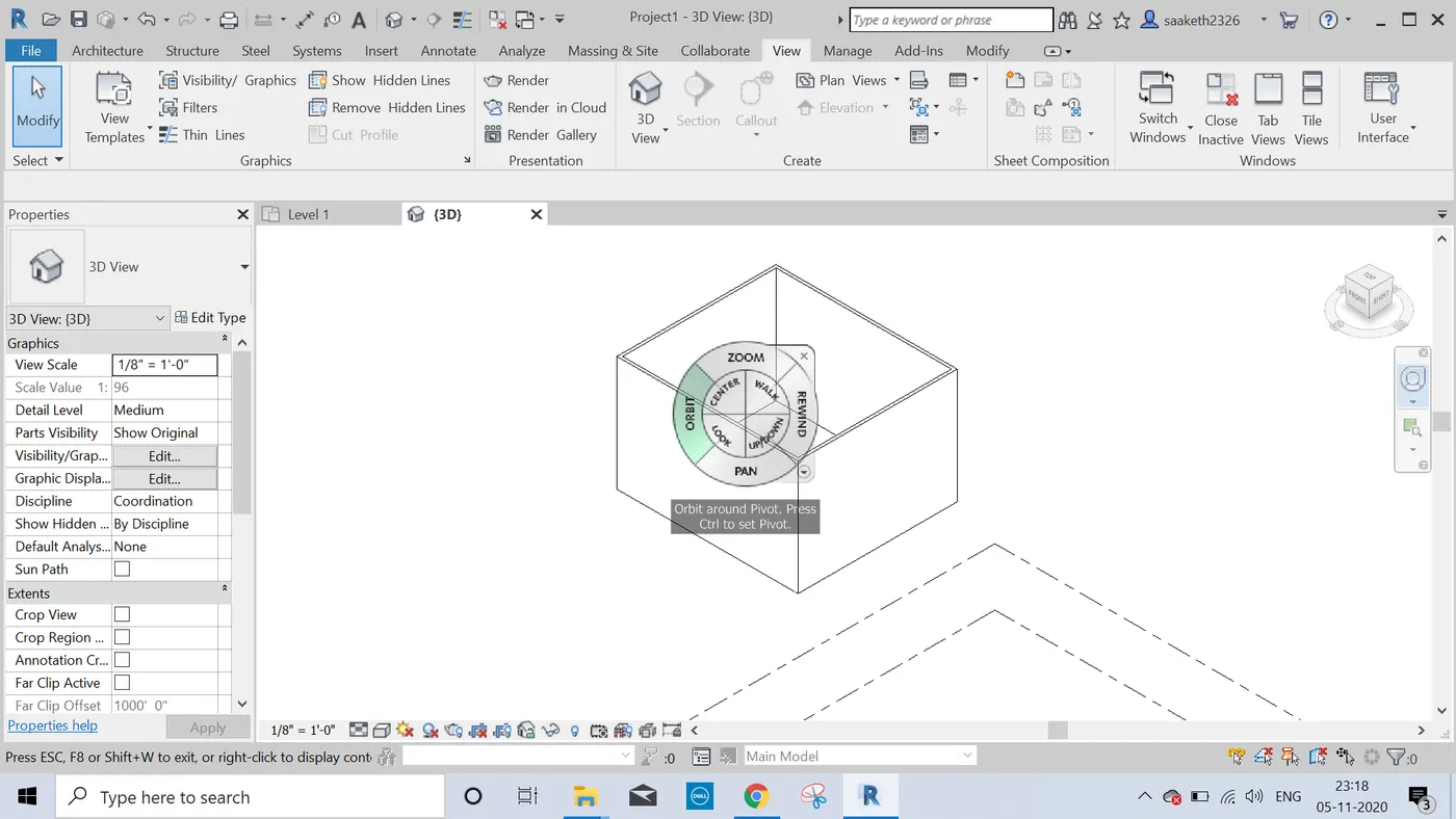
RESULT:
The 3D layout is navigated through view cube and also through orbit option.
- AIM: to use the visibility settings option to switch the model in to shaded, realistic and hidden lines.
TOOLS REQUIRED:
- 3D view
- Visibility option
PROCEDURE:
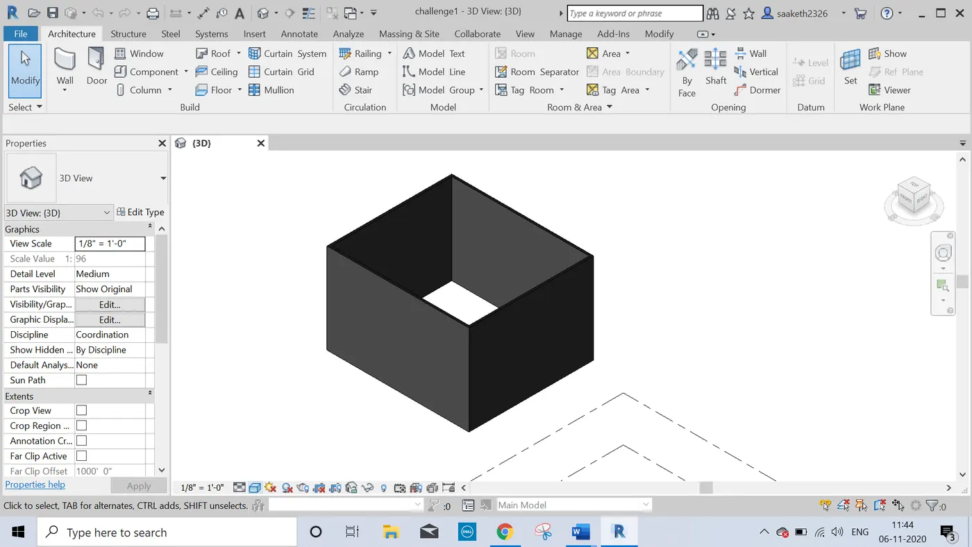
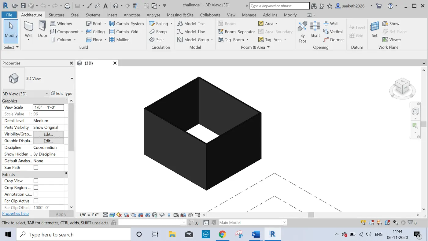
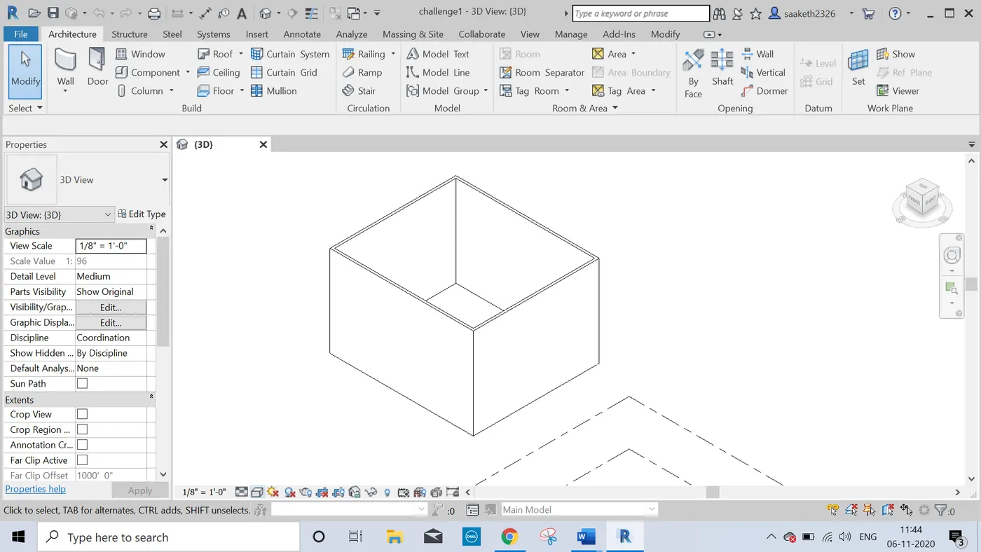
- Open 3D view of the rectangular layout.
- Click the visibility option at the bottom.
- Now select the shaded option for shaded view, realistic option for realistic view and hidden option hidden lines view.
RESULT:
The model is switched to shaded, realistic and hidden views by using visibility option.
- AIM: To turn the sunlight on and off to view shadings in the layout created.
TOOLS REQUIRED:
- Manage toolbar
- Additional settings
PROCEDURE:
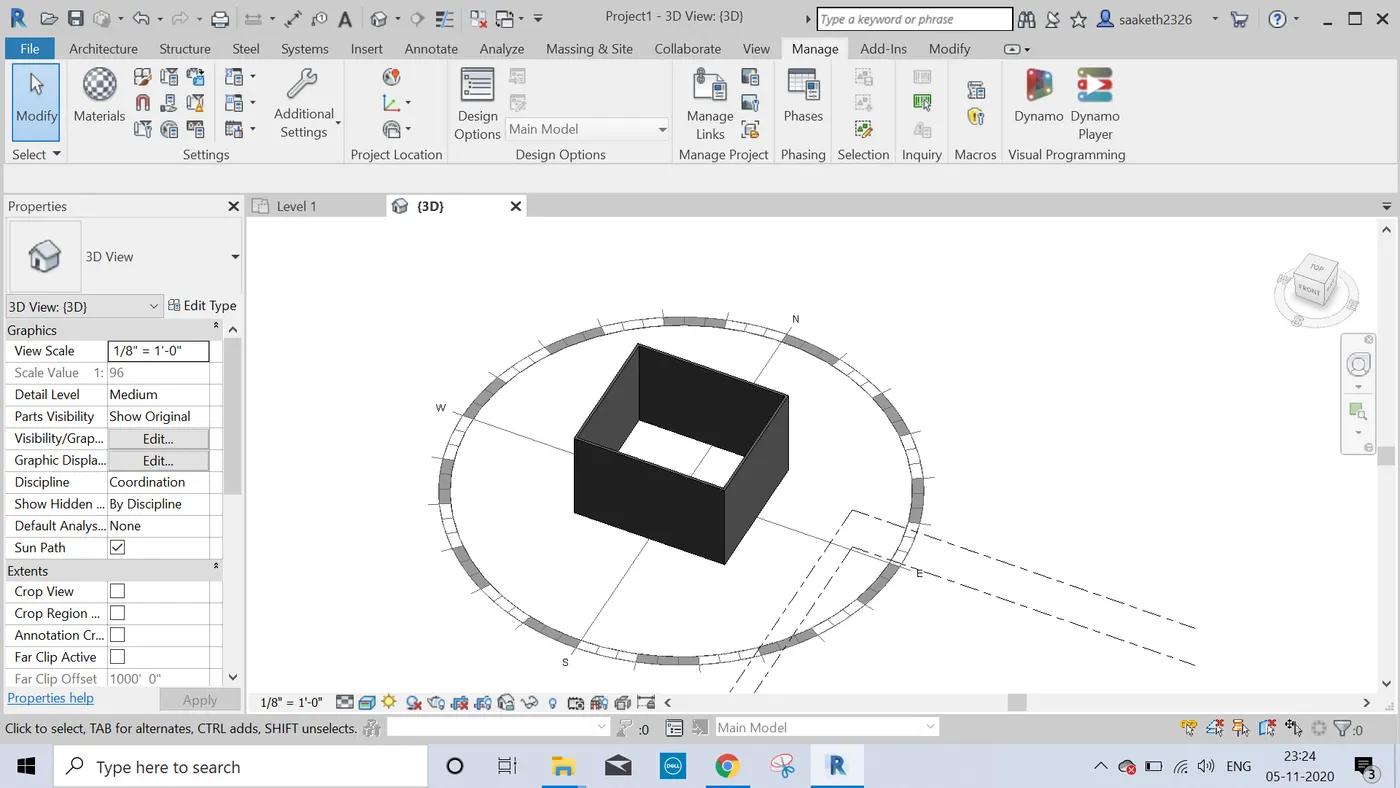
- Click the sunpath option that is visible below. Turn on the sunpath.
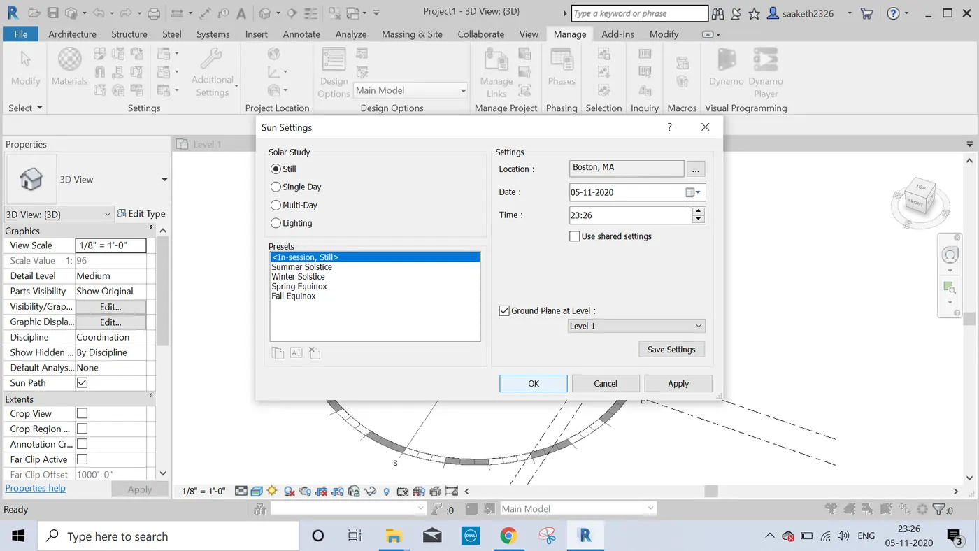
- Now go to manage toolbar and click on additional settings.
- In the additional settings click on sun settings.
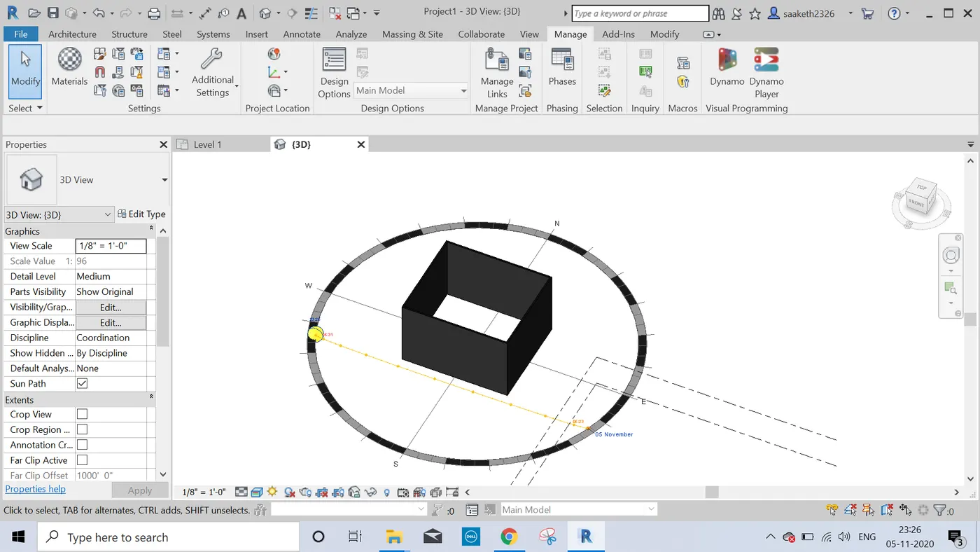
- Click on still and select ok. Now we can view the shadings created.
RESULT:
Sunlight is turned on and off to view shadings of the layout.
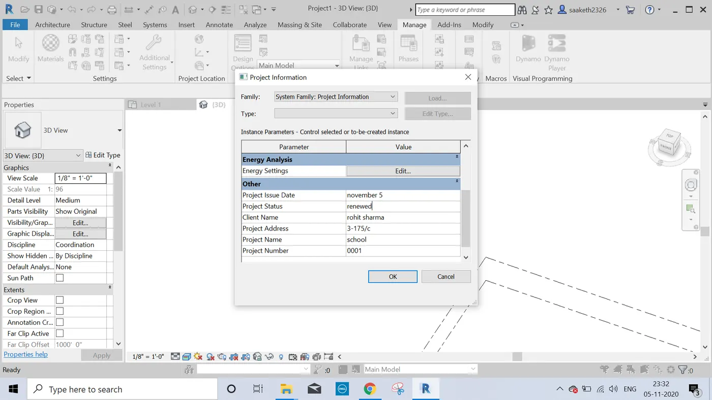
- AIM: To use manage toolbar to enter project settings, project name, and project issue date.
TOOLS REQUIRED:
- Manage toolbar
- Project information
PROCEDURE:
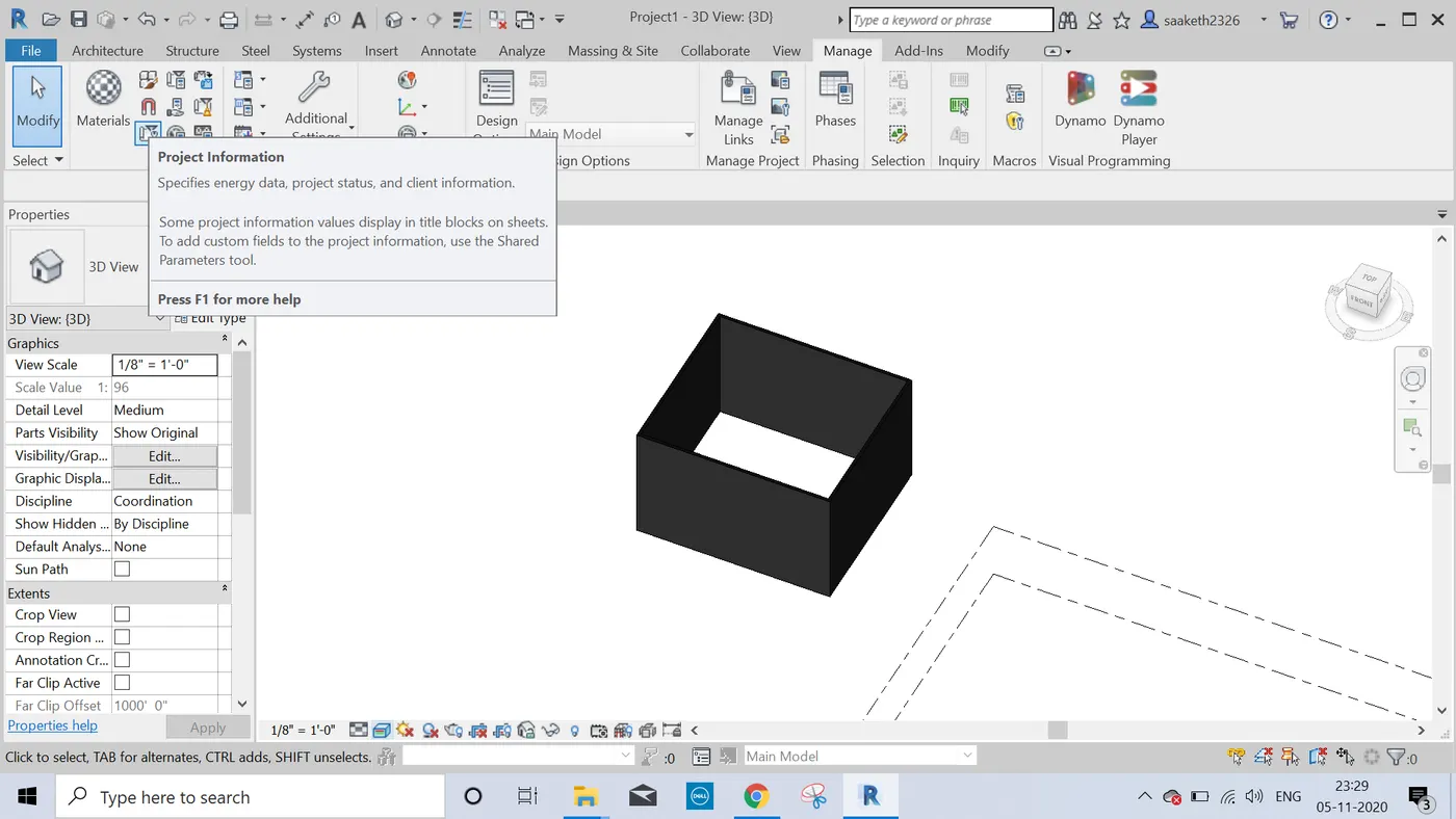
- Click on the manage toolbar.
- Click on project information option.
- Now enter the details of the project created i.e. project name, project issue date, address etc. and click ok.
RESULT:
Project settings, project name and project issue date are entered by using manage toolbar.
11. Analyze toolbar helps us to perform analysis on structural building. it helps to add different types of loads to know the performance of the model. it helps in performing energy optimization and energy analysis of the structural building. it also helps in creating load combinations, boundary conditions and support systems. and to know what are the changes to be made to make the project more efficient.
12. The links that revit supports to be linked to the model are:
- link revit
- link IFC
- DMF makeup
- point cloud
- co-ordination cloud
- link PDF
- link image
13. Collaborate tab is used to link up multiple rivet models together i.e, it helps when different type of engineers are working on same project like structural engineer, mechanical engineer, plumbing etc.,to work with ease and higher efficiency. we can also change the requirements accordingly. this tab supports modelling.