Project 1
- AIM: To model a ceiling from architecture tab above the walls at first floor level using the project saved in week 3.
TOOLS REQUIRED:
- Architecture tab
- Ceiling tool
PROCEDURE:
- Open the project file from week 3.
- click on first floor plan floor plan views.
- Click on architecture tab and select ceiling.
- With the help of boundary lines form a closed where ceiling is required.
- Click ok and the ceiling is formed.
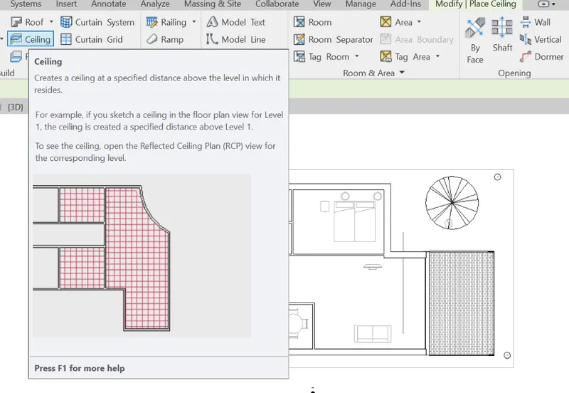
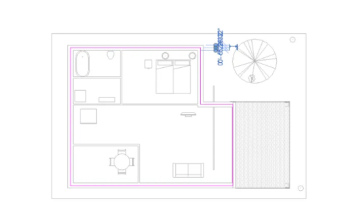
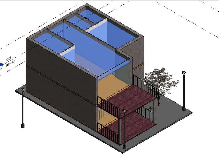
RESULT:
A ceiling is modelled from architecture tab above the first floor level.
- AIM: To model a roof above the ceiling by selecting footprints of the ceiling and also change it’s slope to 10 degrees.
TOOLS REQUIRED:
- Architecture tab
- Roof tool
- Properties browser
PROCEDURE:
- Select the first floor level plan again.
- Click on the architecture tab and select roof tool with footprints.
- Now draw the boundary lines for the roof above first floor.
- Click ok so that roof is formed.
- To change the slope select the roof in 3D view.
- Now in the properties browser change the slope to 10 degrees.
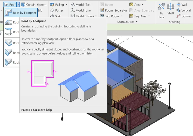
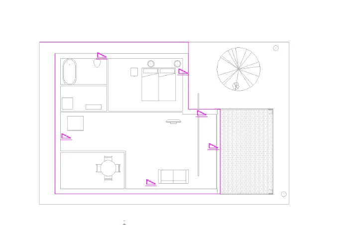
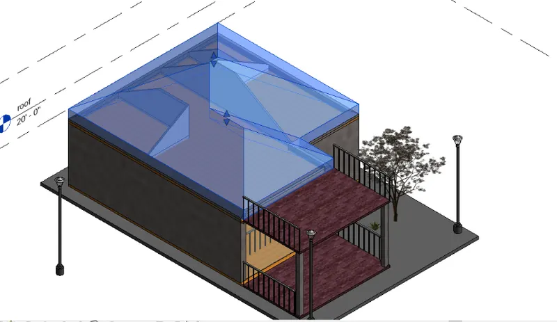
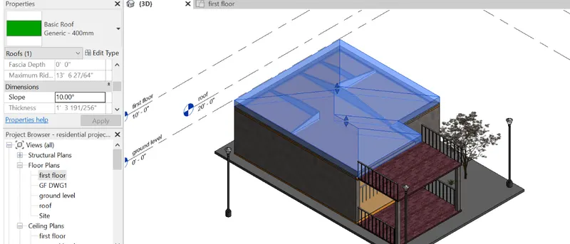
RESULT:
Required roof is modelled above the ceiling with 10 degrees slope.
- AIM: to create plan views for ground floor level and first floor level including all the walls, floors and components.
TOOLS REQUIRED:
- View tab
- Plan views icon
- Floor plan
PROCEDURE:
- Open the residential building project file.
- Click on the view tab and select plan views.
- In plan views select floor plan.
- Now unselect the option at the bottom.
- We can see 3 levels, click on the level which is required.
- If ground level is selected a duplicate plan view of ground level is created.
- If first floor level is selected then a duplicate plan view of first floor level is created.
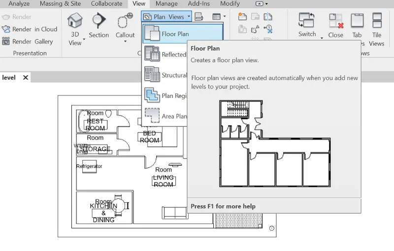
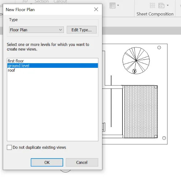
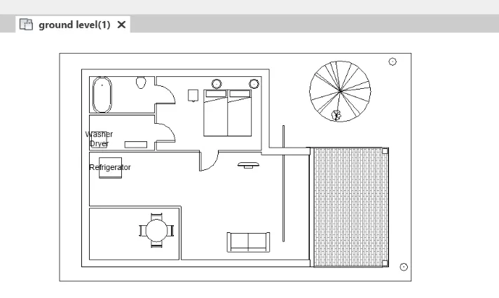
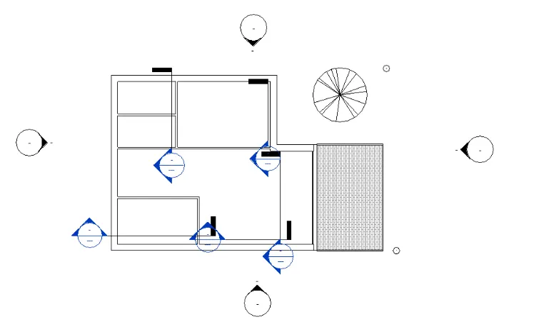
RESULT:
The plan views of ground level and first floor level are created which includes walls, floors and components.
NOTE:
- only procedure of architecture plan is explained.
- Because plan views for structural isn’t explained till week 4.
- AIM: to add dimensions to all the walls and floors with reference to the longitudinal and transverse grids. The grids are based on the components.
TOOLS REQUIRED:
- Annotate tool bar
- Architecture tab
- Grids
- Aligned dimensions
PROCEDURE:
- Open the project file.
- Click on the architecture tab and select grids.
- Draw both longitudinal and transverse grids such that the dimensions of the walls are known with respect to the components.
- Name vertical grids with numbers and horizontal grides with letters.
- Now click on annotate toolbar and select aligned dimensions icon.
- Now measure the walls and floors with reference to the components and grids.
- Now mention the dimensions accordingly.
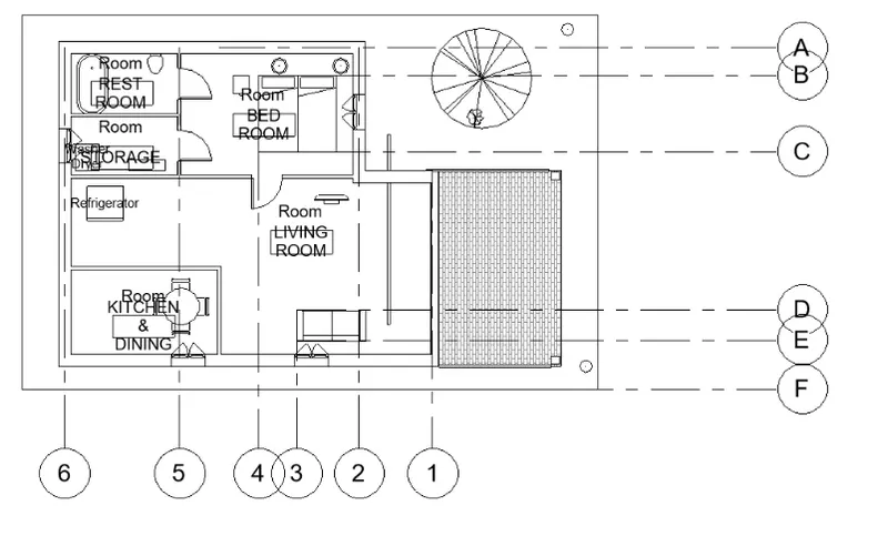
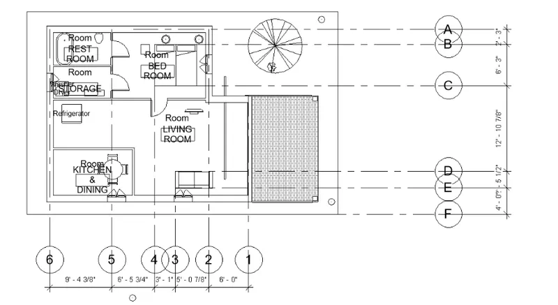
RESULT:
The dimensions are added to walls and floors with reference to the longitudinal and transverse grids based on components.
NOTE:
Here also this topic related to structural plan isn’t explained. So only procedure for architectural plan is explained.
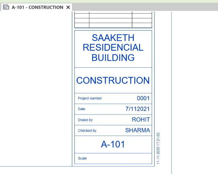
- AIM: To create a sheet template from the view tab and to adjust the parameters.
TOOLS REQUIRED:
- View tab
- Sheet template
- Parameters
PROCEDURE:
- Open the project file.
- Click on the view tab.
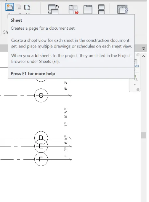
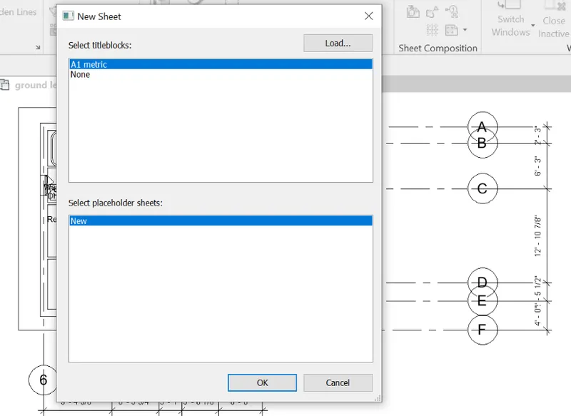
- Select the sheet template.
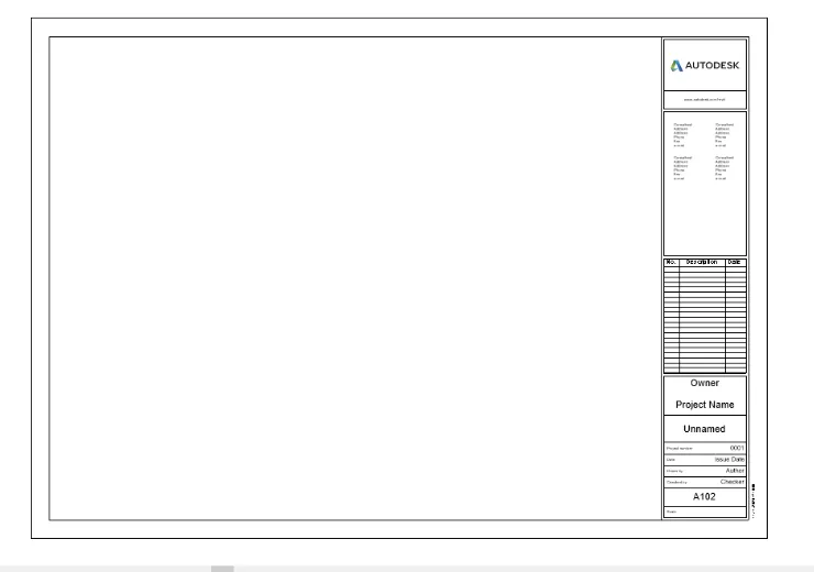
- Create a new sheet and name it accordingly.
- To change the the parameters edit the parameters at the bottom right.
- Change the project name, number and date etc,
RESULT:
A new sheet is created using view tab and the parameters are adjusted.
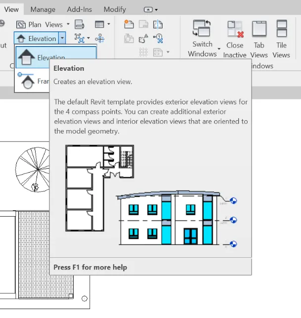
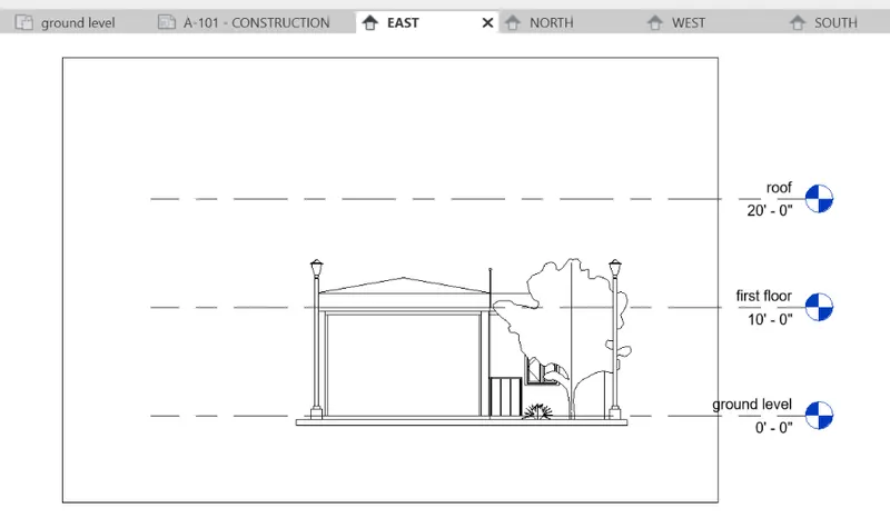
- AIM: To use the elevation tab to create the elevation views in east, north, west and south directions.
TOOLS REQUIRED:
- View tab
- Elevation tab
- Views
PROCEDURE:
- Open the project.
- Click on view tab and select elevation.
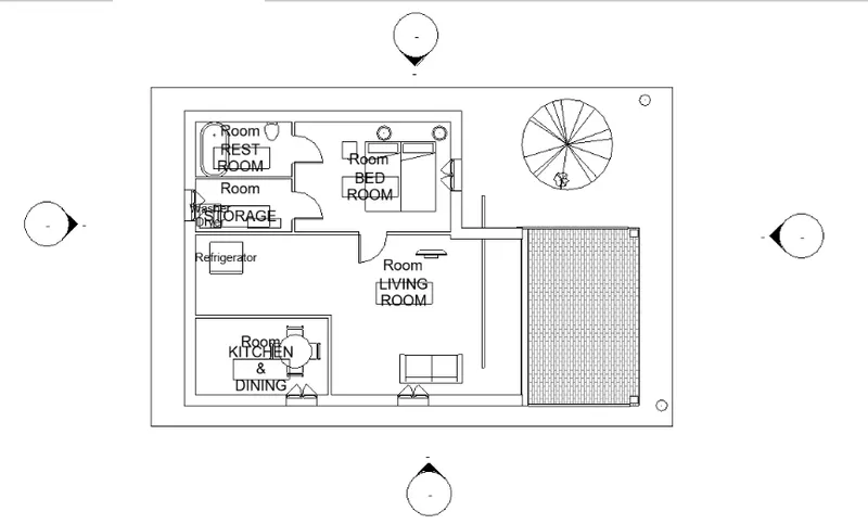
- Mark the elevations at 4 directions I,e, north, south, east and west.
- Now the elevations are created.
- To view elevations click on any of the direction.
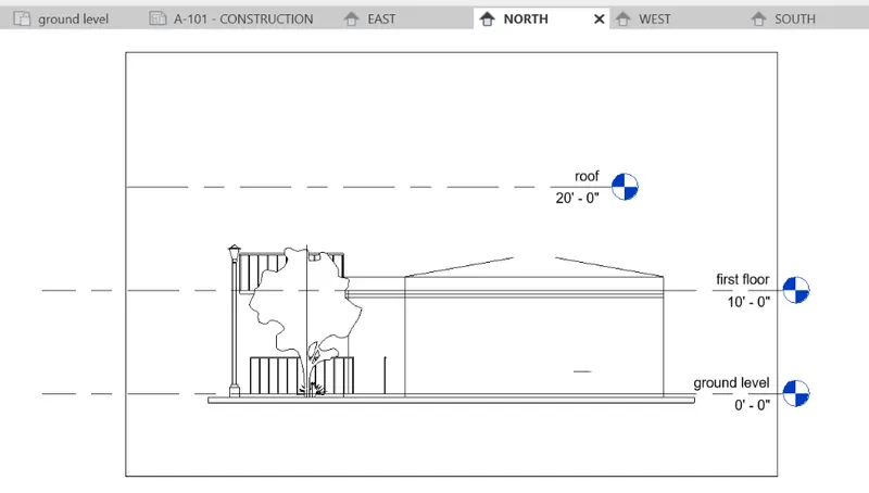
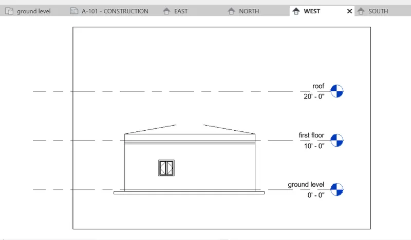
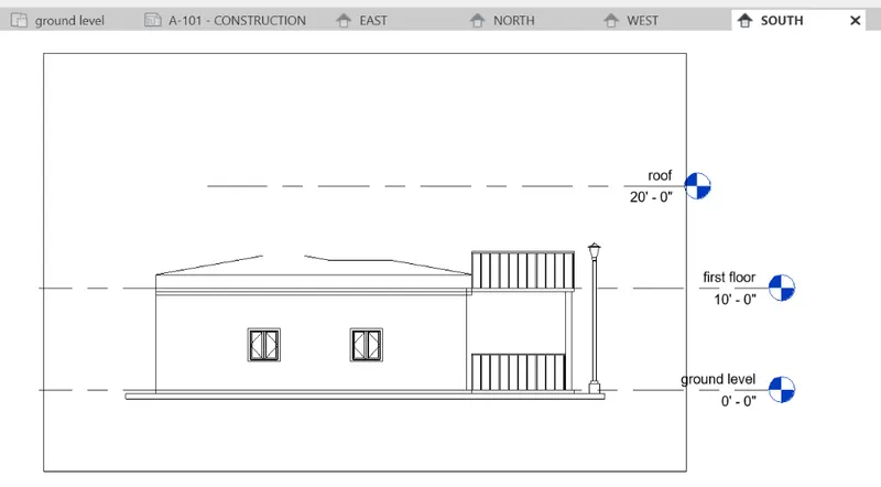
RESULT:
The elevation views are created in north, south, east and west directions using elevation tab.
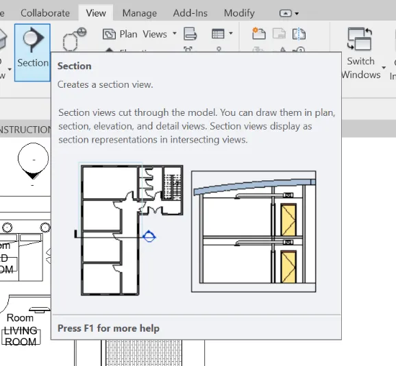
- AIM: To produce section cut through each room by cutting either longitudinally or in transverse direction.
TOOLS REQUIRED:
- View tab
- Sections
PROCEDURE:
- Open the project file.
- Click on view tab.
- Select sections tool.
- Now draw the sections to all the rooms like rest room, storage room, living room, kitchen, dining and bedroom.
- Area of the section should be based on the area of room.
- Sections are created under the properties.
- Now we can view different sections using them.
RESULT: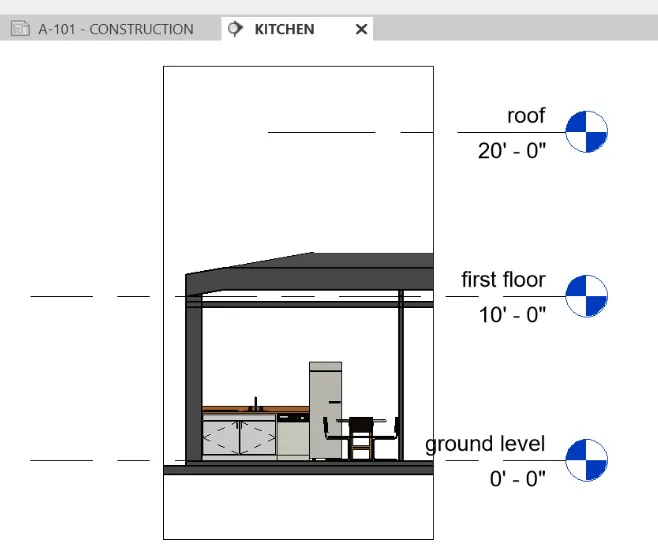
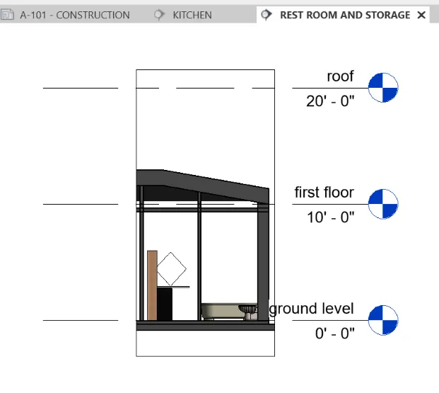
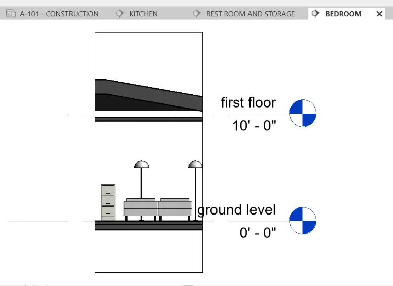
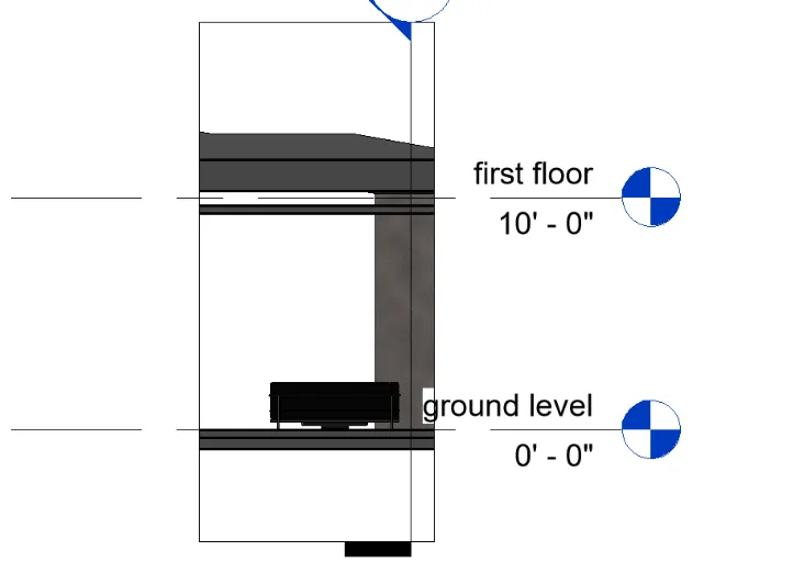
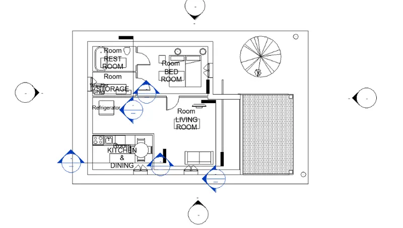
Finally the section cuts are provided to each room.
- AIM: To classify the views, plan views, section views and elevation views to either design or documentation category using property browser
TOOLS REQUIRED:
- Property browser
- New category
PROCEDURE:
- Open the project file.
- Click on the properties browser.
- Right click on the views option.
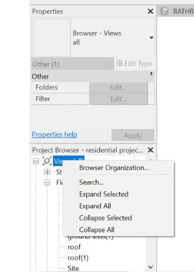
- Now click on “ new” option to create new category.
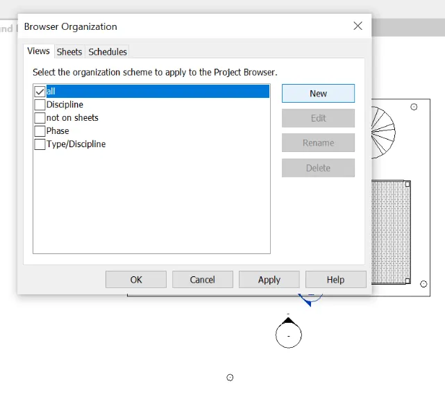
- Name the classification as “design and documentation”.
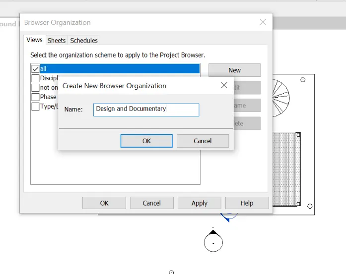
- Now a category is created.
- Set the views option as design and documentation category.
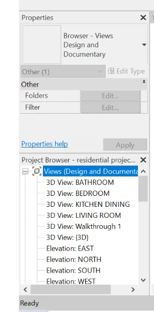
- Now all views and elevations are visible below the views ( design and documentation).
RESULT:
The views, plan views, section views, and elevation views are classified under design and documentation category.
9. AIM: To create multiple sheets using sheet template as follows:
- A 101 - ground floor architectural plan
- A 102 - first floor architectural plan
- A 103 – roof plan
- A 201 – north south elevations
- A 202 – east west elevations
TOOLS REQUIRED:
- View tab
- Sheet template
- Insert tab
- Image
PROCEDURE:
- Now open the project file.
- We know that different views are created.
- Click on view tab and select sheet template.
- Now on the sheet image of required plan using image tool.
- The images are stored as screenshots.
- Now name the sheet as given.
- Do the same with all the plans and elevations that are to be added to the sheets.
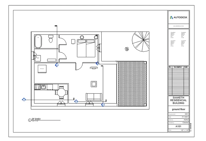
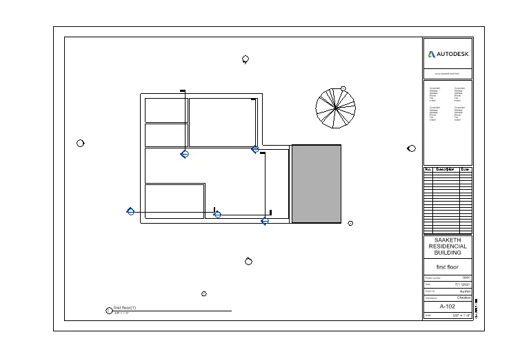
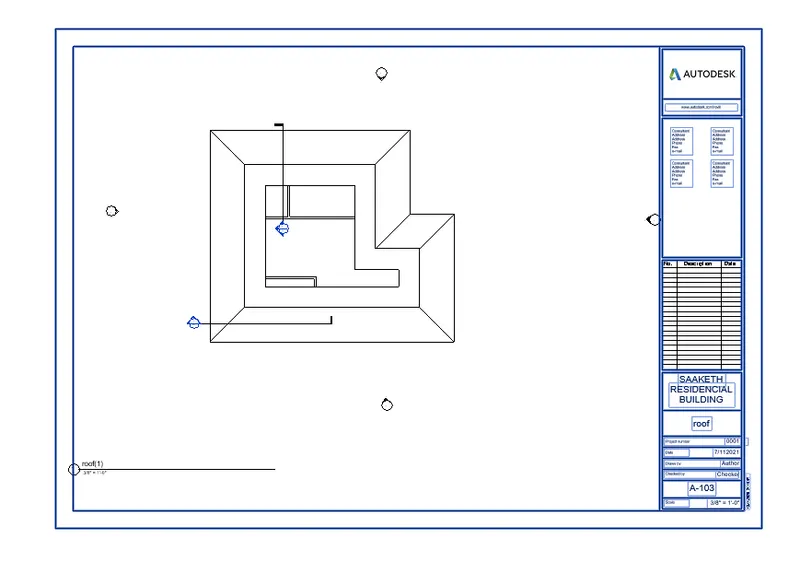
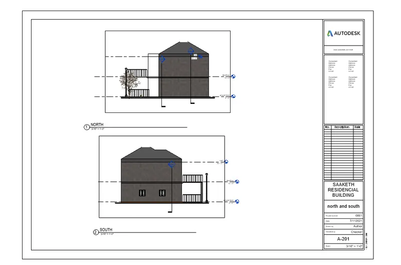
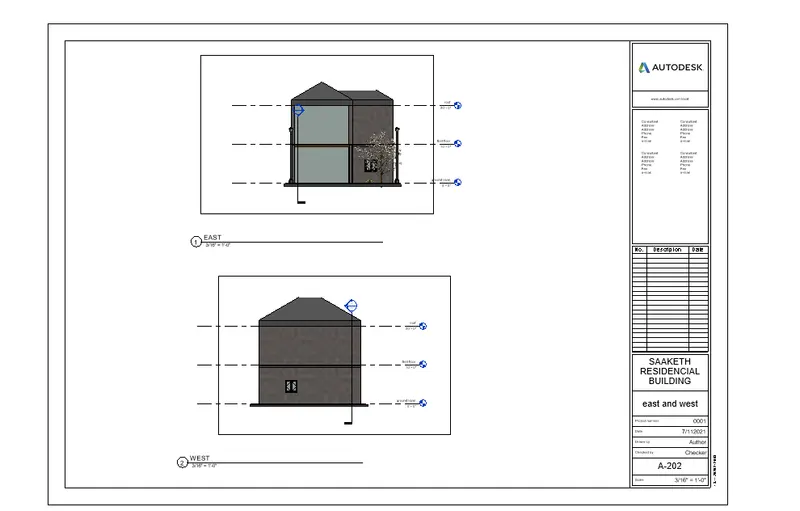
RESULT:
The required sheets are created and named accordingly.
NOTE:
The structural plans are not included because the topic is not discussed yet.
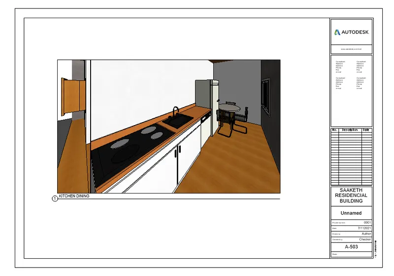
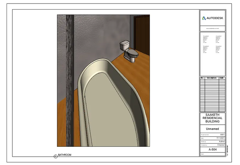
- AIM: to create a camera specific view in each room and based on the views the sheets are to be created.
TOOLS REQUIRED:
- View tab
- 3D view
- Camera
- Sheet template
PROCEDURE:
- Open the project file.
- Click on the view tab and select camera in 3D view.
- Now place the camera in each room and the views are created below 3D view.
- Name the views by the name of the rooms.
- Now save all the views to the computer.
- Create a new sheet with the sheet template.
- Insert image of any room and mention the name accordingly.
- Now the sheets with 3D views of different rooms will be created.
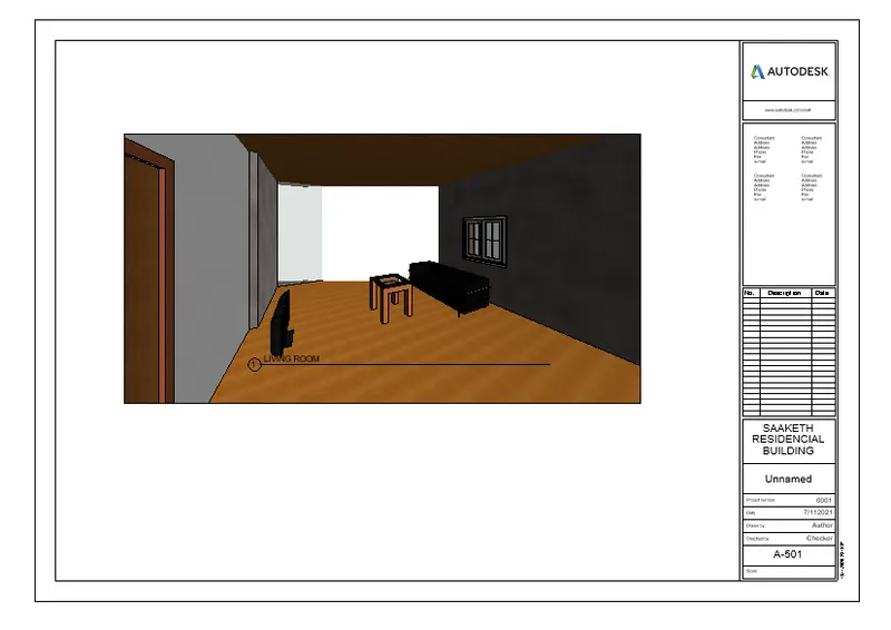
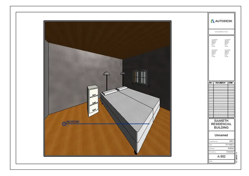
RESULT:
The camera specific views are created in each room and based on the views sheets are created.