Week 2 Challenge
- BIM software is used individuals, businesses and government agencies who plan, design, construct, operate and maintain buildings and diverse infrastructures, such as water, refuse, electricity, gas, communication utilities, roads, railways, bridges, ports and tunnels. Building information modeling is a process supported by various tools, technologies and contracts involving the generation and management of digital representations of physical and functional characteristics of places. Building information model are computer files which can be extracted, exchanged or networked to support decision-making regarding a built asset. Features of BIM: the 3D model enables users to understand relationships between spaces, materials, and various systems within a physical structure. BIM software can be used for every step of the process, from planning to design to construction. Benefits of using BIM over 2D CAD tools:
- BIM drawing tools have advantage of being faster than 2D CAD tools.
- BIM offers a more complete representation of a building’s design.
- It is time saving compared to 2D CAD.
- Engineers from different fields like structural, mechanical and plumbing can work together using BIM. It makes the work more efficient.
- AIM: to understand the concept of categories, families, elements, instances in revit.
TOOLS REQUIRED:
- Insert tab
- Load family
PROCEDURE:
- Create a rectangular layout with the help of walls in architectural template.
- Now click on insert tab and select load family.
- Now we can see different categories.
- Click on the residential door and select double glass door click ok.
- Now click on the door in architecture tab and select the double glass door in properties and place it to one of the wall.
- Click view tab and view in 3D.
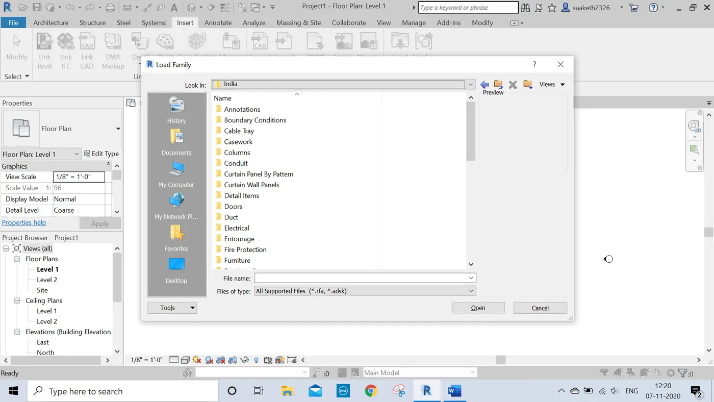
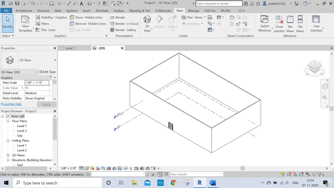
RESULT:
Hence we understand to know the concept of categories, families and elements in revit. Here, i inserted a double glass door from doors family.
- AIM: to set-up a project. (complete process)
TOOLS REQUIRED:
- File menu
- Manage tab
- Save as option
PROCEDURE:
- Click on the file menu and select new project with architectural template.
- Click on save as option and name the project with appropriate name.
- Click on manage and setup the units in project units.
- Now click on project information and fill all the details.
- Now click on save as option in file menu , beside the name we can see options click on it.
- Now in the maximum backups enter 3 an click okay to save.
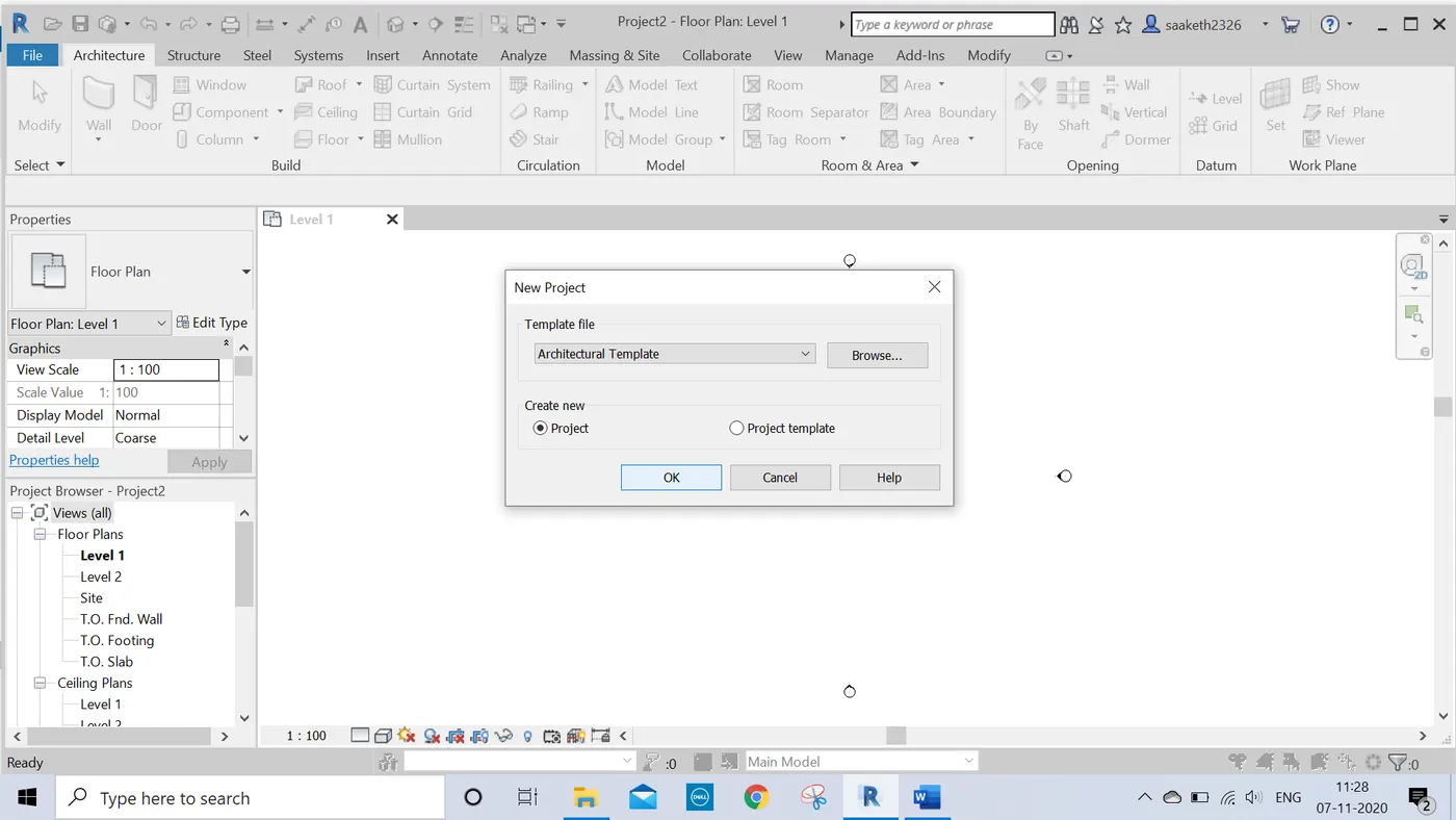
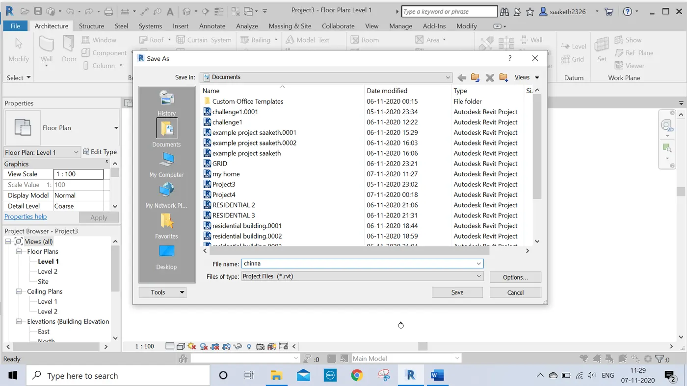
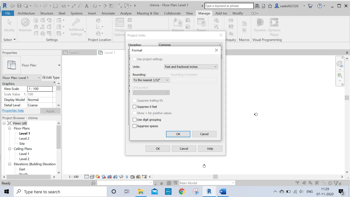
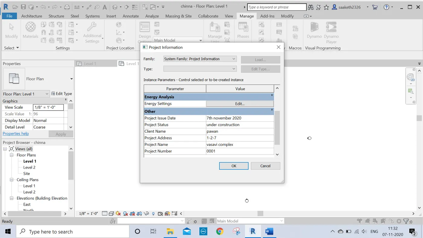
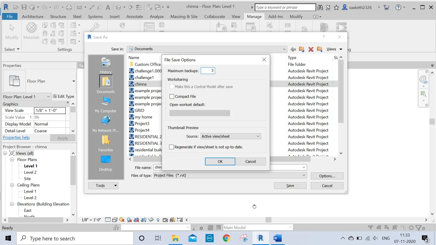
RESULT:
The project is being setup accordingly.
- AIM: To understand the concept of levels and grids.
TOOLS REQUIRED:
- Structure tab
- Levels
- Grids
PROCEDURE:
- Create a new project with structural template.
- Click on the east view.
- We can see different levels.
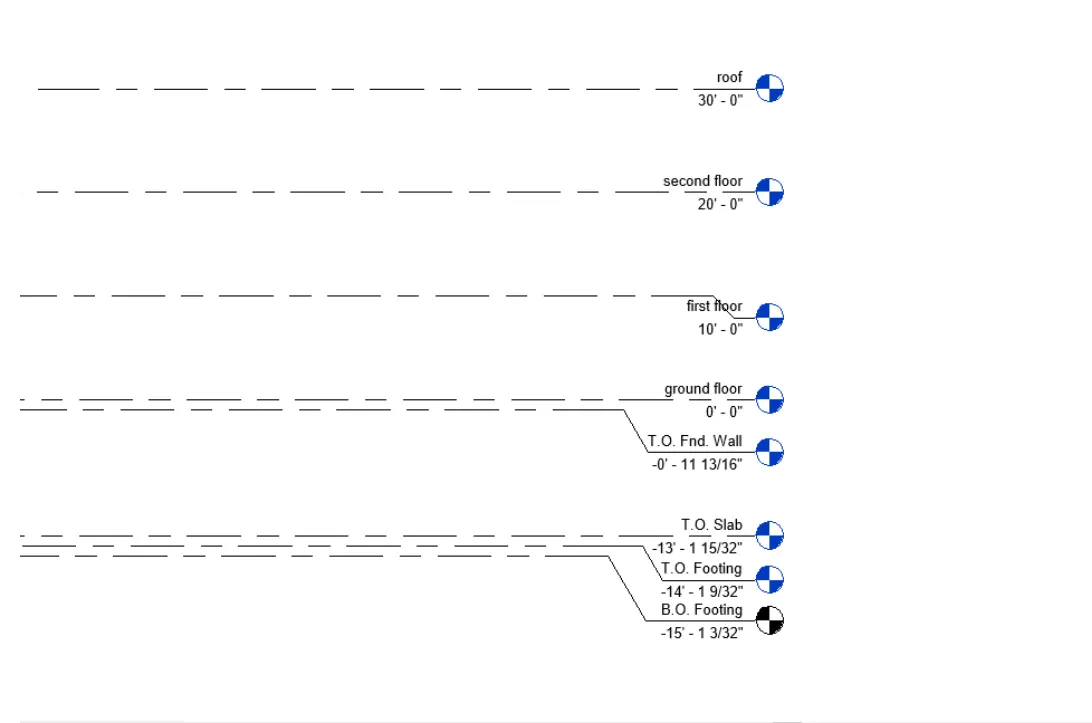
- Double click on level 1 and change it’s name to ground floor.
- Do the same with level 2 and change it’s name to first floor. Maintain the distance of 10’ between the ground floor and first floor.
- Now click on levels in structure tab.
- Create two new levels above the first floor such that one is 10’ above it and the other is 20’ above first floor.
- Rename both levels first one as second floor and second one as roof.
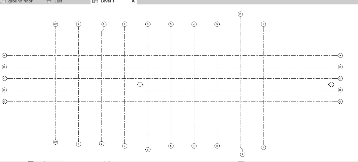
- Click on grids in structure tab.
- Create 5 horizental grids such that distance between lines is 10’.
- Name the horizontal grids from top to bottom as A,B,C,D and E.
- Now create the 10 vertical grids with a distance of 20’ between the lines.
- Both horizontal and vertical should intersect each other.
- Name the vertical grids from left to right with numbers 1 to 10.
RESULT:
Hence we came to know the concept of levels and grids and the required levels and grids are drawn.
- AIM: To create a conceptual layout of residential unit.
TOOLS REQUIRED:
- Architecture tab
- 3D view
- Walls
PROCEDURE:
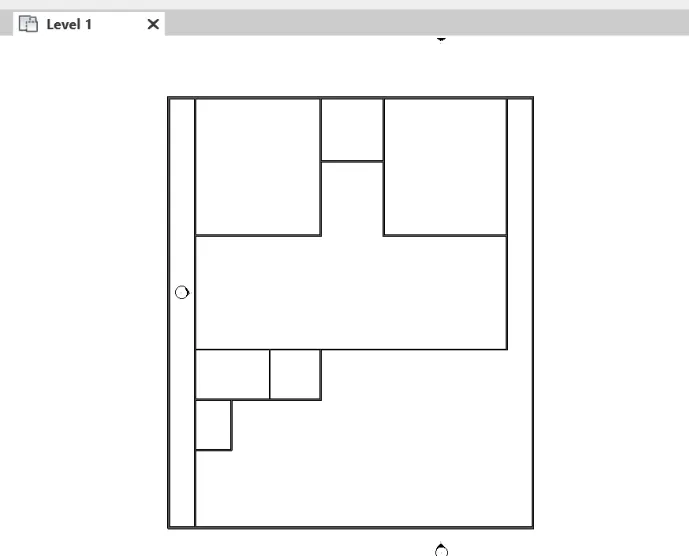
- Create a boundary layout of residential unit using wall in architecture tab.
- Use interior wall for the interior part of the layout to divide rooms.
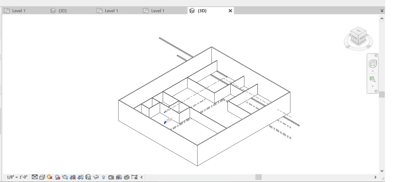
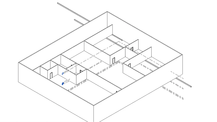
- Click on view tab and select 3D view to view in 3D.
RESULT:
The conceptual layout of residential unit is created.
- AIM: To include dimensions of room and components we plan to add.
TOOLS REQUIRED:
- Annotate toolbar
- Architecture tab
- Room option
PROCEDURE:
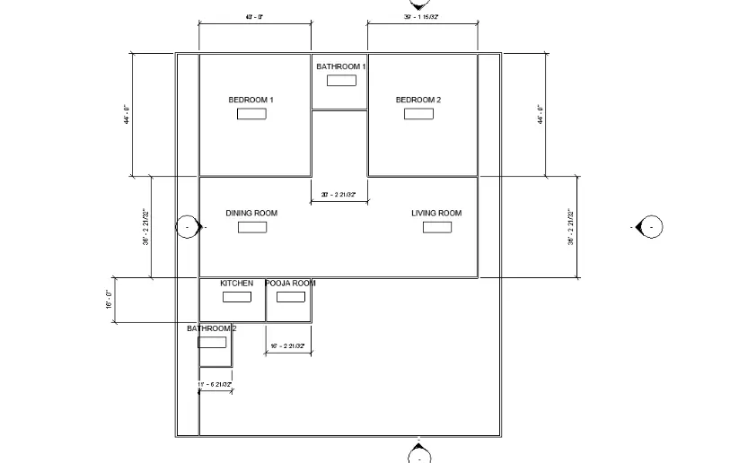
- Open the created layout of the residential unit.
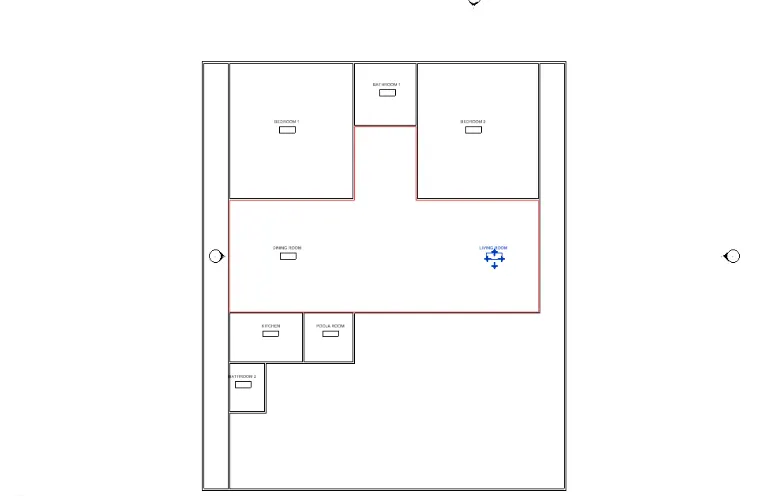
- Now click on aligned in annotate toolbar and place the dimensions of all rooms.
- Now in architecture tab click on room.
- Now place the cursor on different rooms and select.
- We can name the rooms now.
- We can also add components to different rooms.
RESULT:
Dimensions and components are included which are needed to be added.
- AIM: to identify the residential model elements such as door, windows, windows, tables, chair, couch, bed, lamps from library and insert them to the model.
TOOLS REQUIRED:
- Previously created residential unit
- Insert tab
- Load family
PROCEDURE:
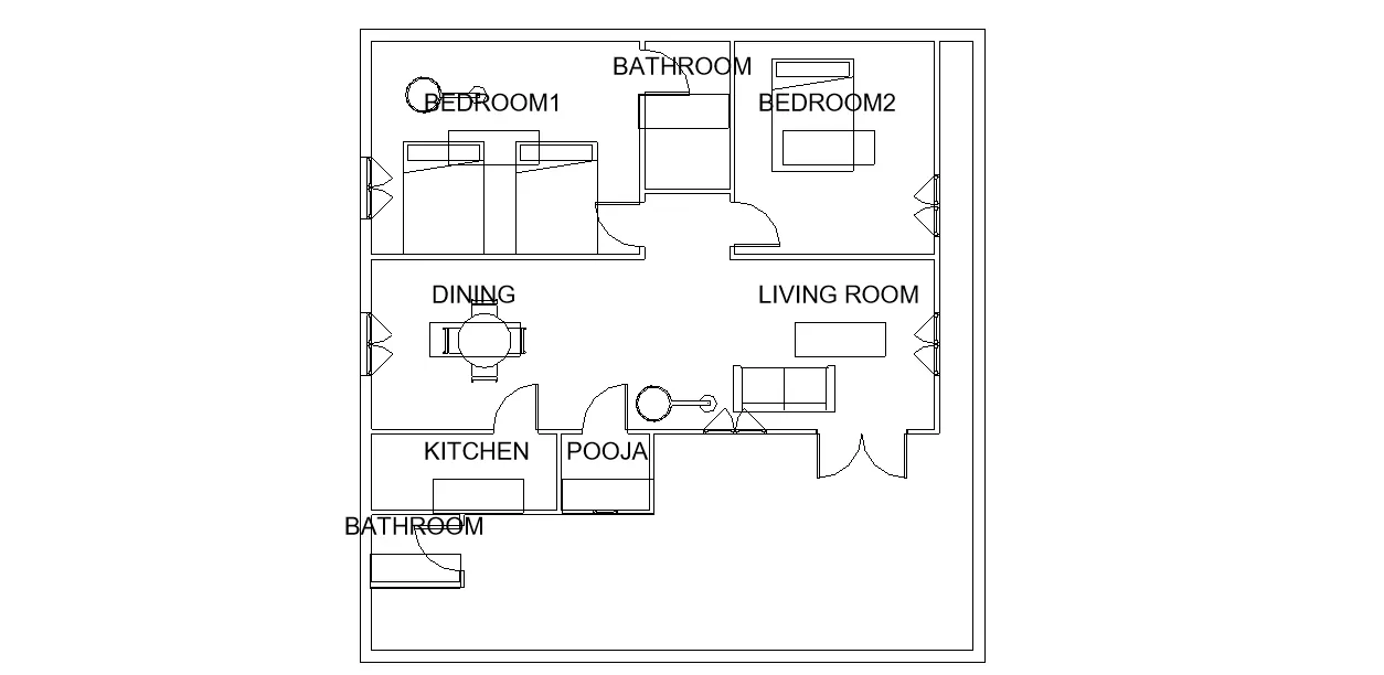
- Open the residential unit previously created.
- Now click on insert tab and select load famiy.
- Now we can see different categories, families and elements.
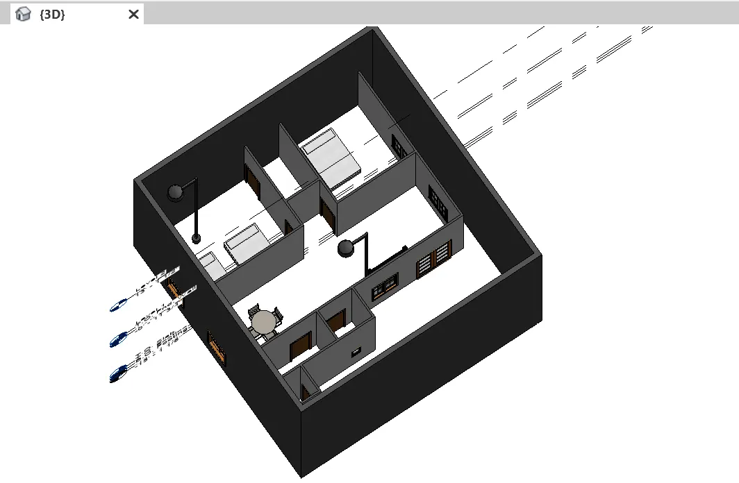
- Select the required elements and place them accordingly.
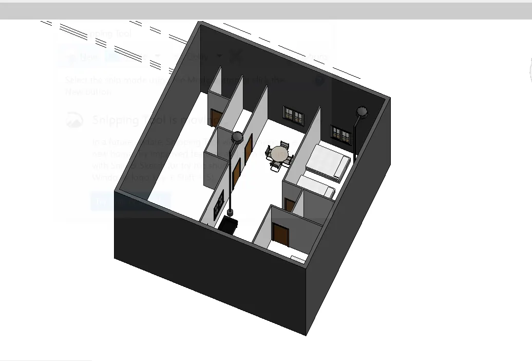
RESULT:
The residential model is added with required elements from the library.