Week 1 Challenge
1st ans)
Aim:- To create a new project (Structural / Architectural / Construction template ) and name the project appropriately from file menu
Procedure:-
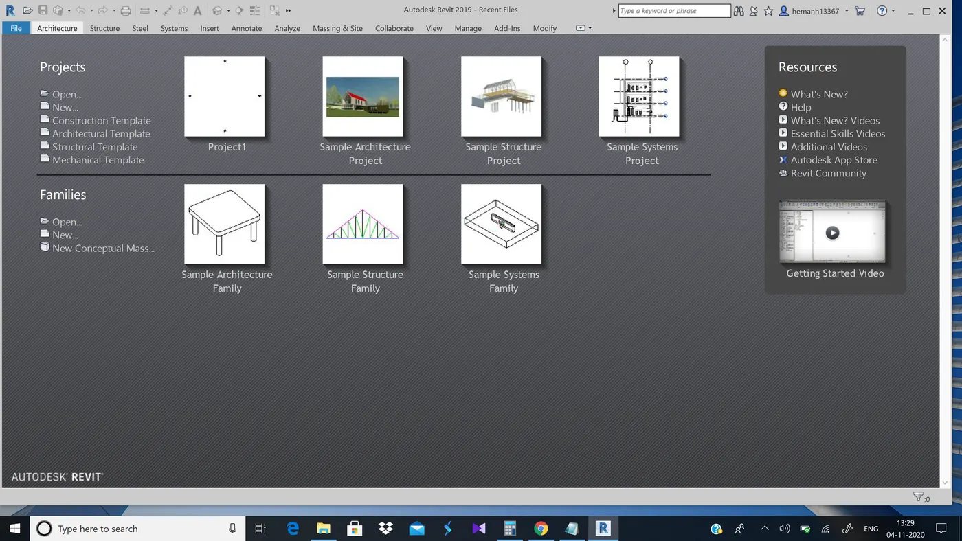
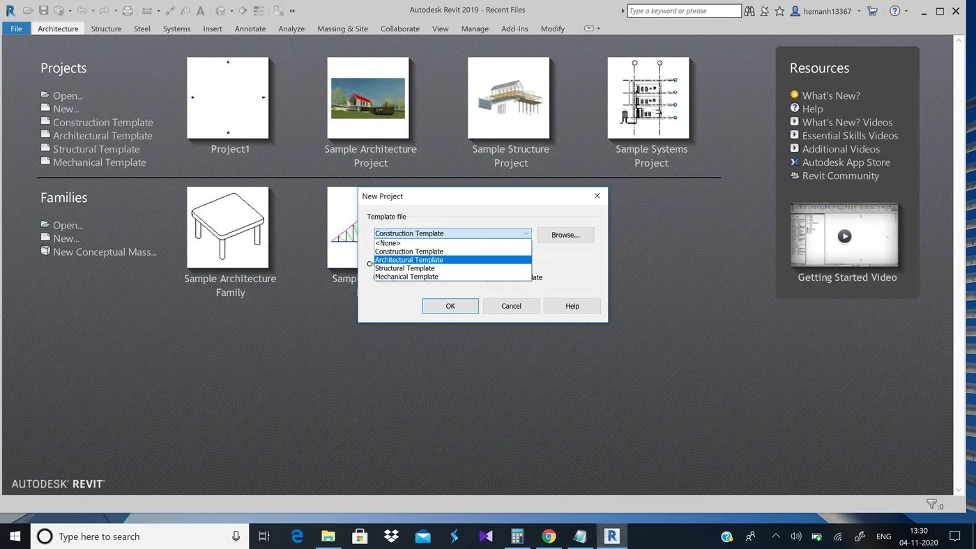
- Select the new option and you will see a pop up
- From the template file select architectural template
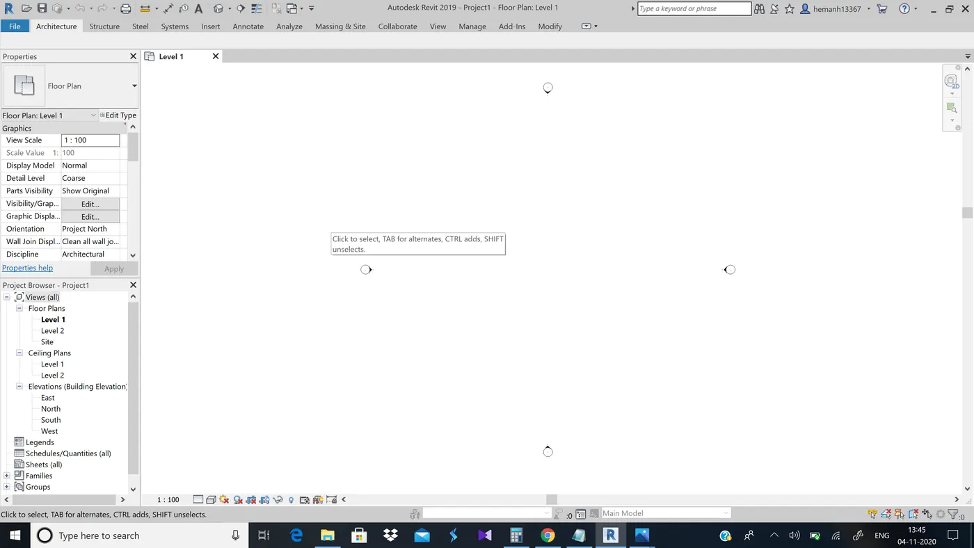
Result:- Now the new project is created and is named as Floor plan:level 1
2nd ans)
Aim:-To save the new project file and open using icons from file toolbar
Procedure:-
Step 1:-
- Select the save option(beside open)
- Then a pop up is seen and you can save it in the desired place
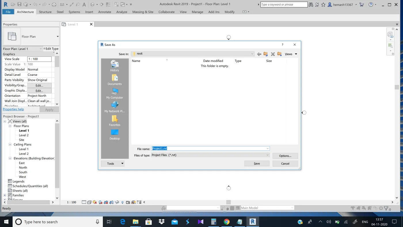
Step 2:-Now using the open icons from file tool bar we can open the saved file
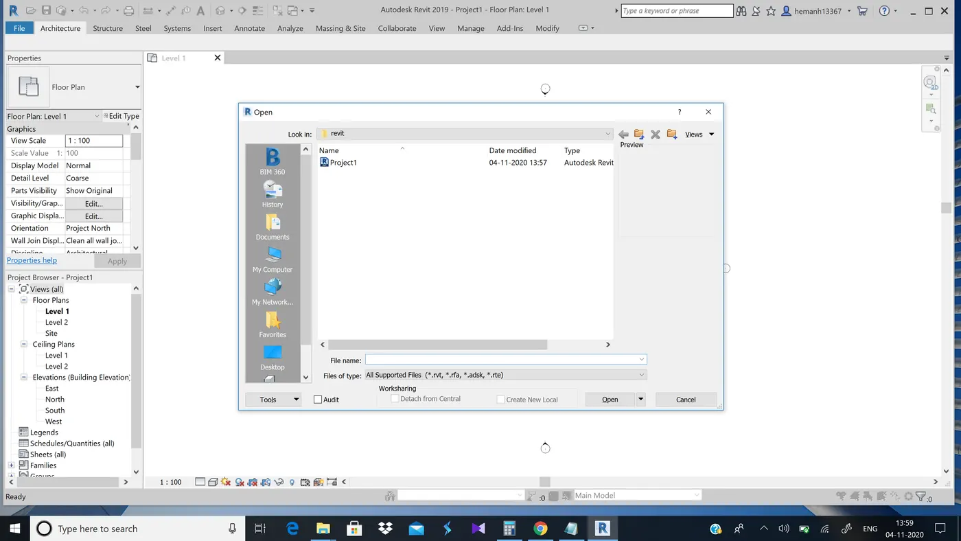
Result:-The file is now opened opened again after saving
4th ans)
Aim:-To create a rectangular layout of wall 40'-0" x 35'-0".
Tools used :-
wall option from architecture
rectangle
Procedure:-
Step 1:-Select wall option from architecture tool bar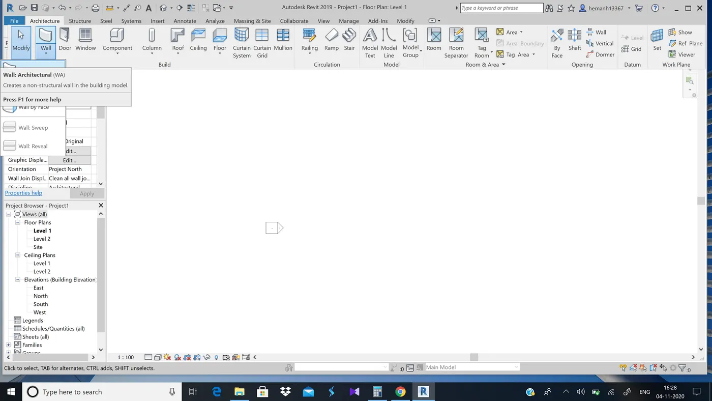
Step 2:-Now select rectangle from modify option
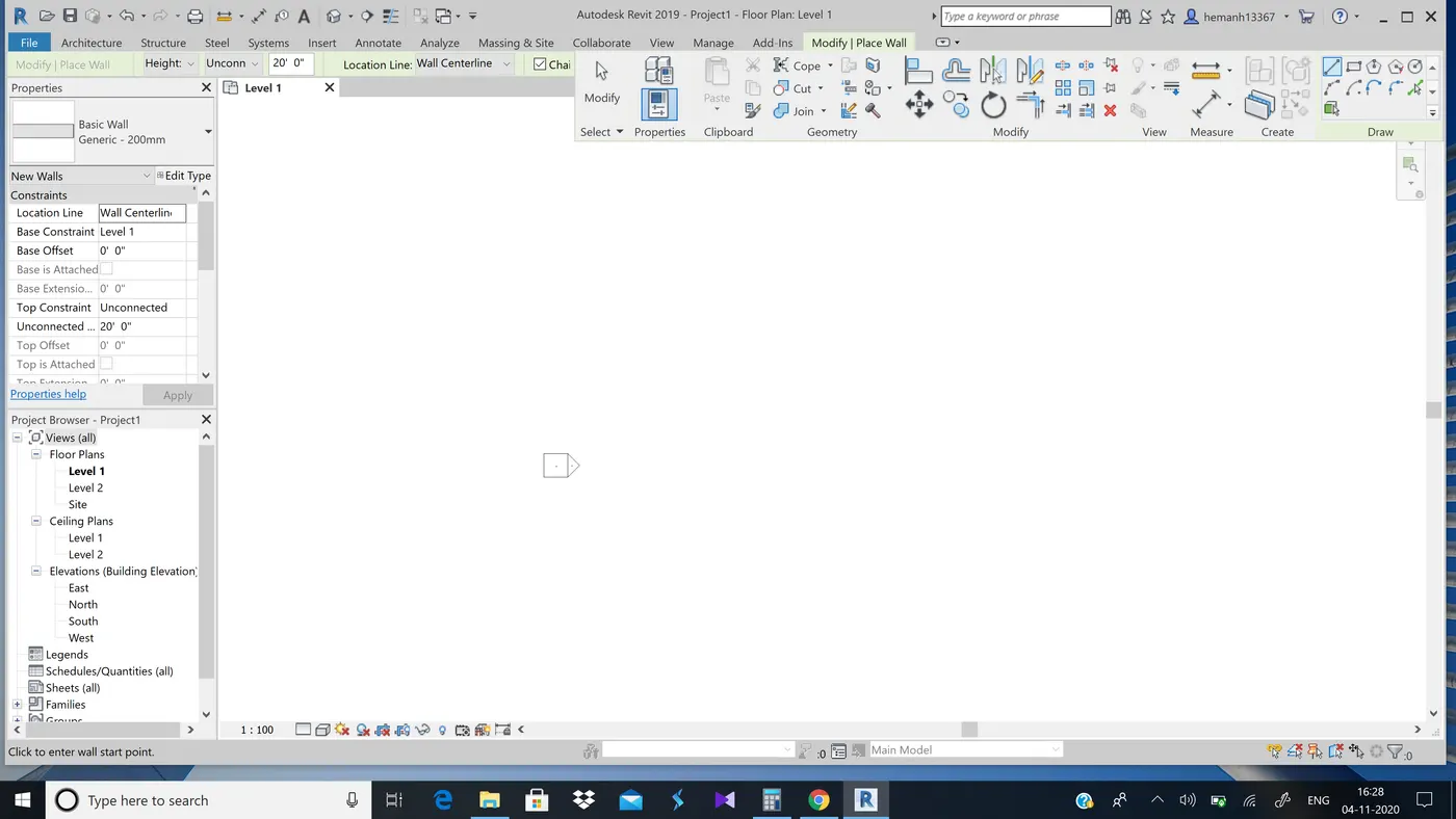
Step 3:-Now draw the wall with given dimensions
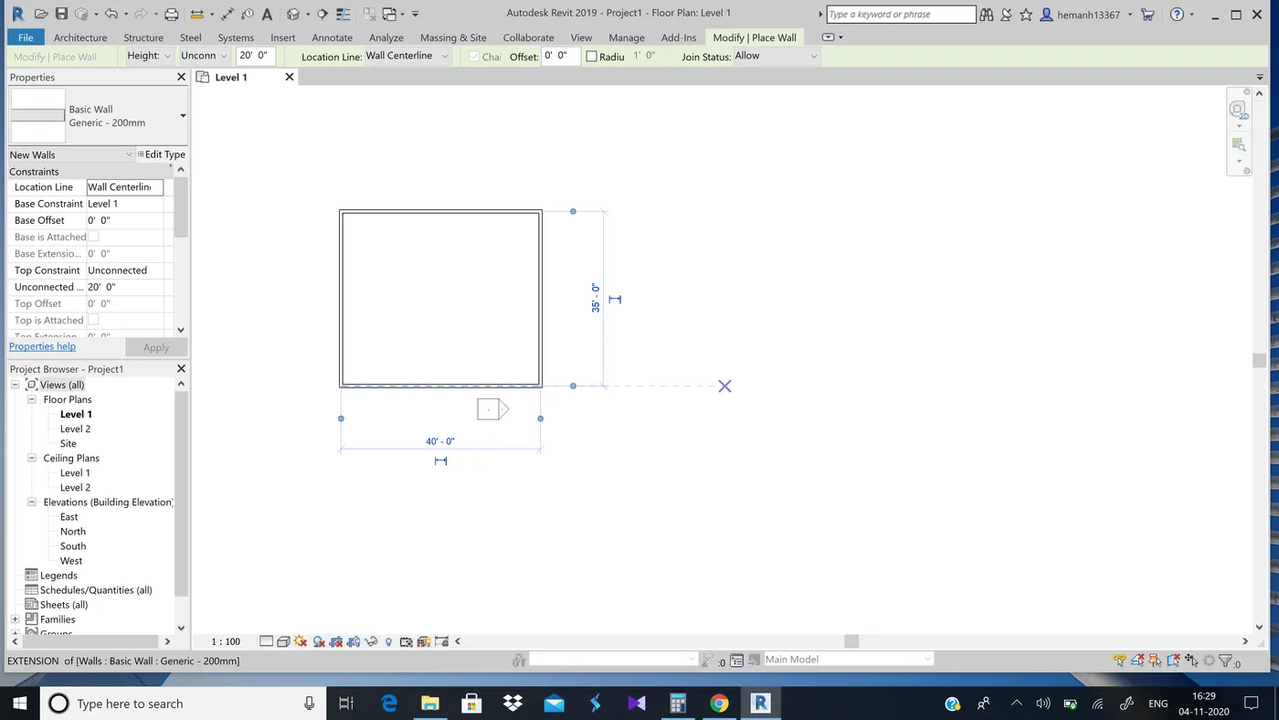
Result:-Recatngular layout of wall with 40'-0" x 35'-0" is created
4 ans)
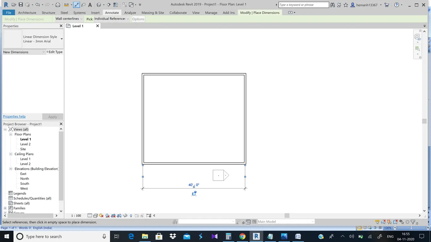
Aim:-To add dimensions to the layout using aligned option from annote tool bar.
tools used:-
aligned option
procedure:-
Step 1:-Select aligned option from annotate tool bar
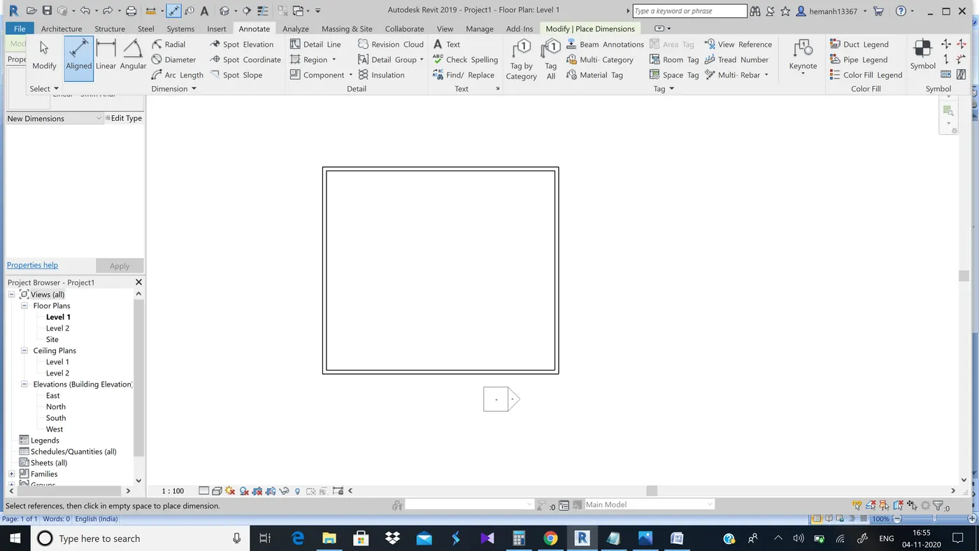
Step 2:-Now measure the layout horizontally
Step 3:-Now measure the layout vertically
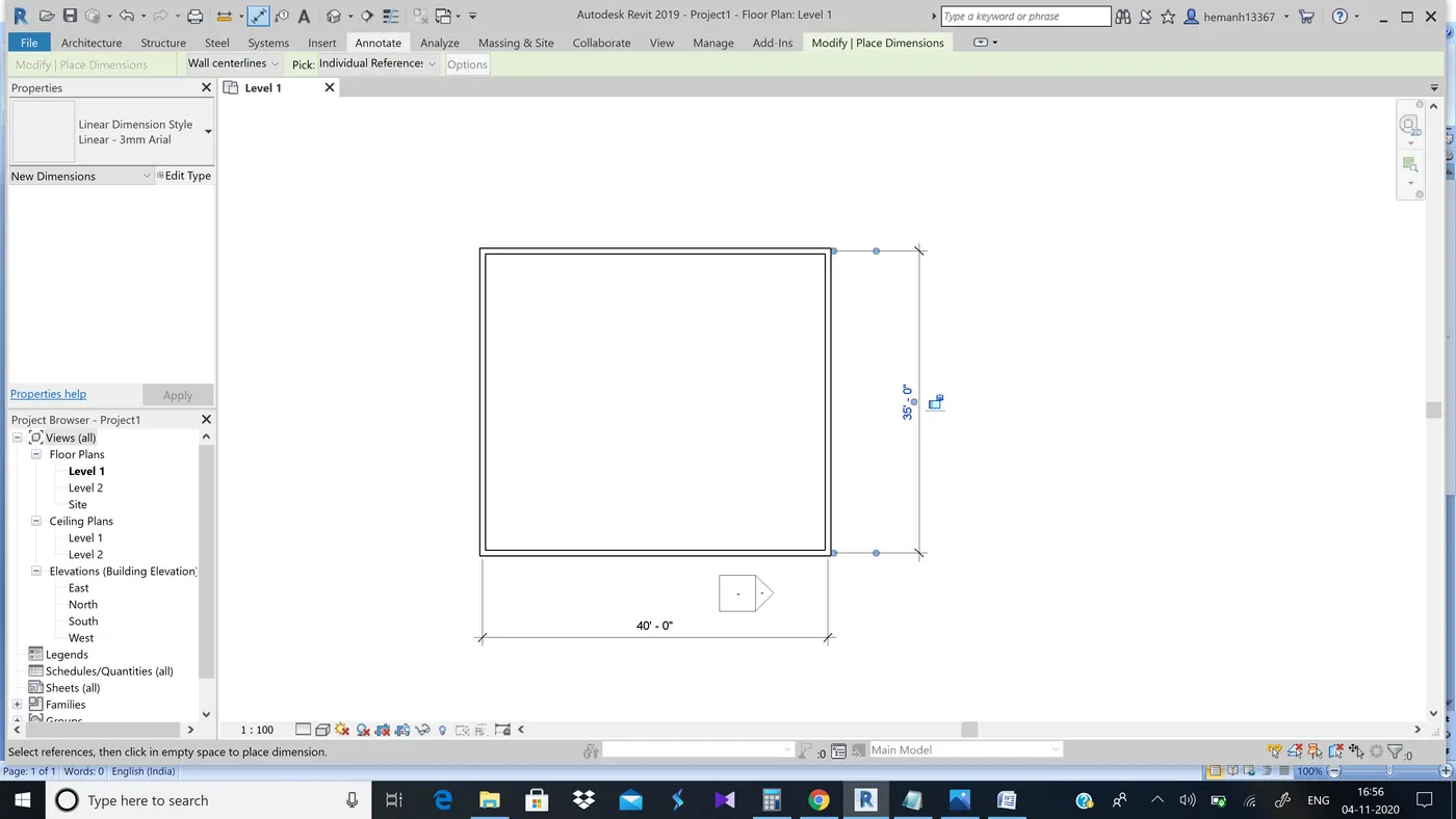
Result:-Dimensions added to the layout using aligned option from annotate toolbar
5th ans)
AIM:-To use the properties browser to switch to different wall types
Tools used:-properties options from wall
Procedure:-
Step 1:-
- Select the wall from the already existing layout and you will see properties on left side of the software
- Now select the desired wall type from wall types
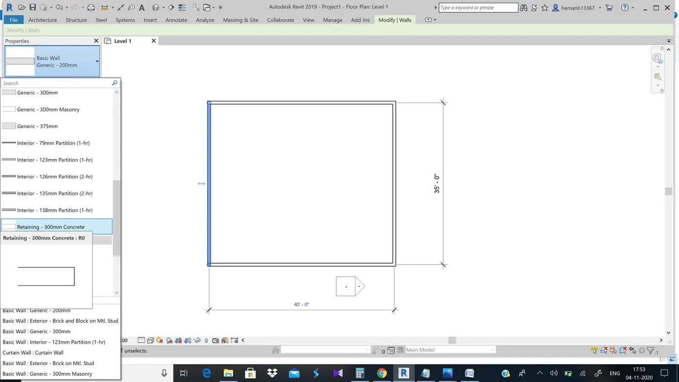
Step 2:-Similarly follow the process on to the second side of wall and continue it on the remaining sides
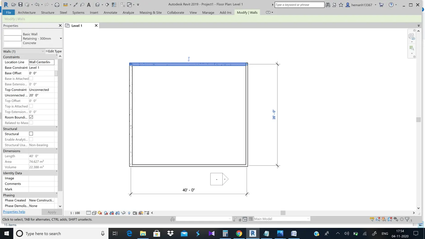
Result:-We have changed the wall types
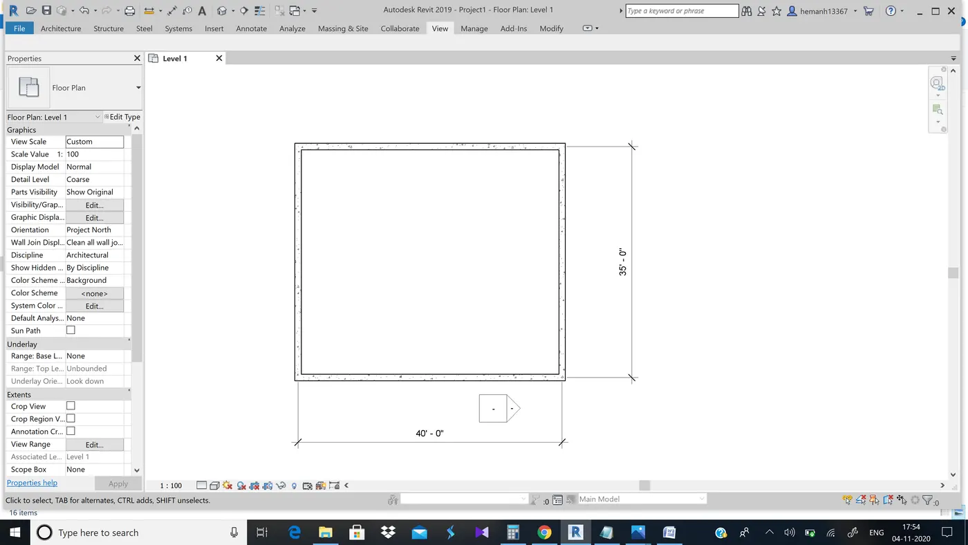
6th ans)
Aim:-To create a 3D view from the tool bar and save the file with appropriate name.
Tools used:-3D view option
Procedure:-
Step 1:-From the view option select 3D view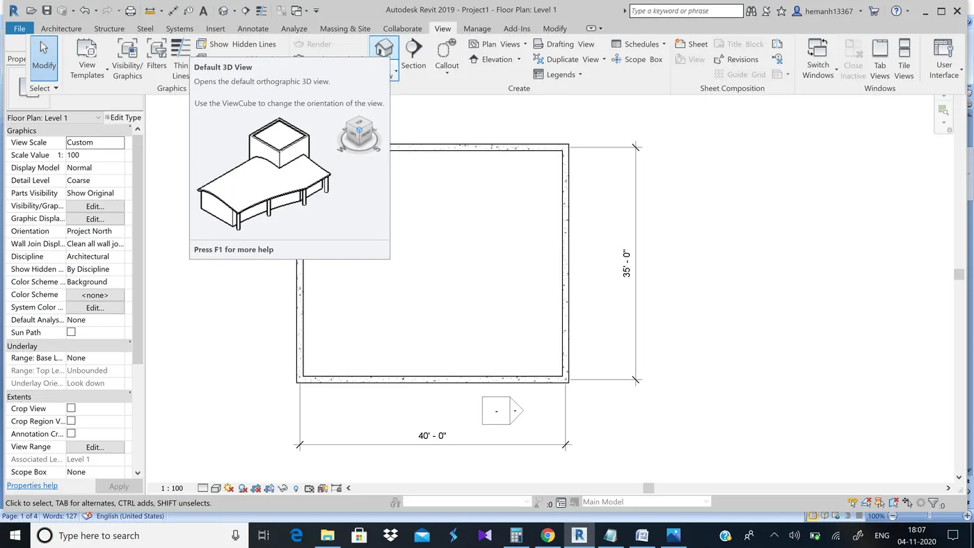
Step 2:-Now you will able to see the 3D view of the layout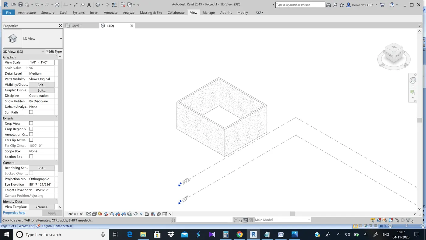
Step 3:-Now right click the 3D image which is present on the top right corner and select save view option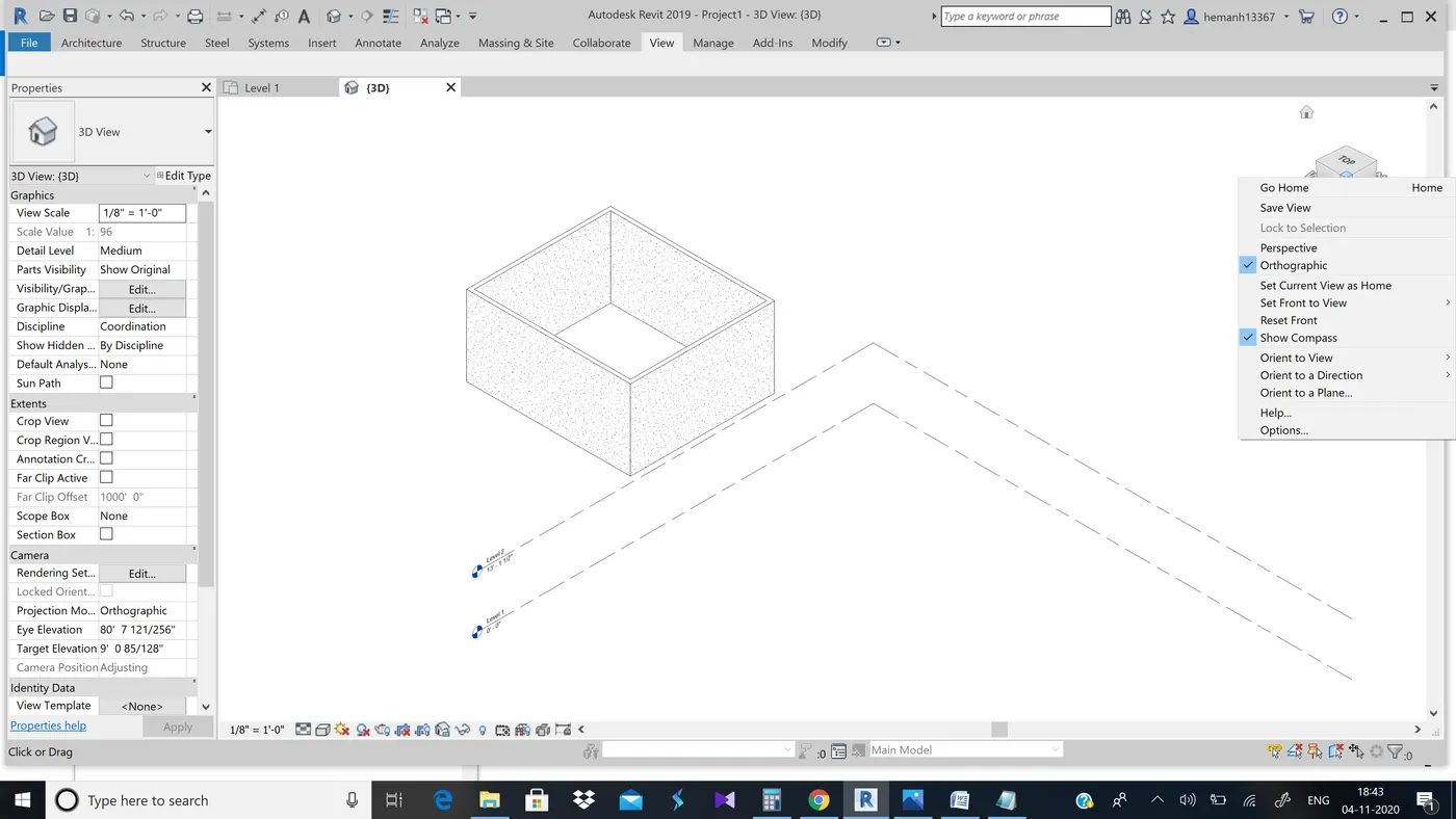
Step 4:-Now save the image with desired name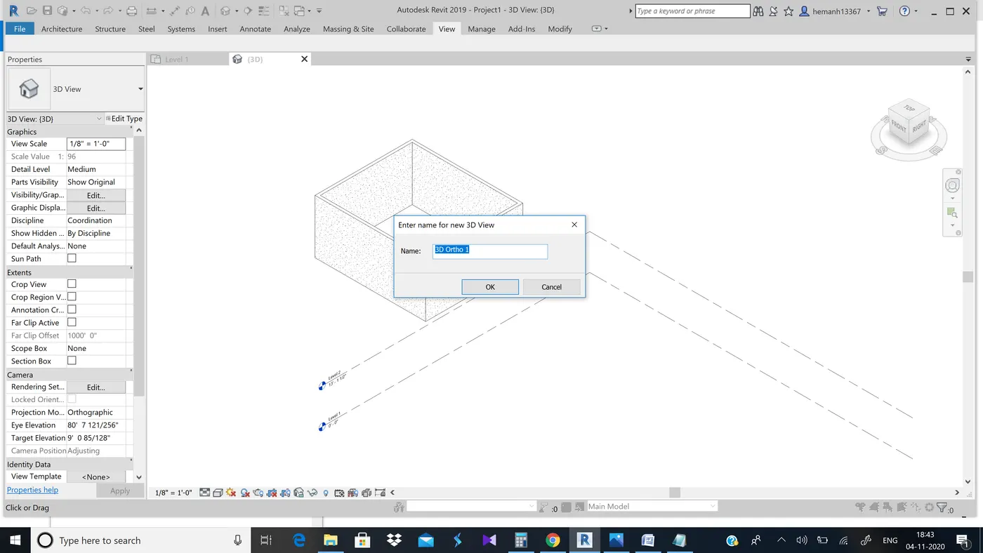
Result:-3d view of the layout
7th ans)
Aim:-To navigate through the 3D model using view cube and orbit throught the model layout created.
Procedure:-We can navigate by using the view cube by rotating it in the desired direction and pan using the mouse scroll.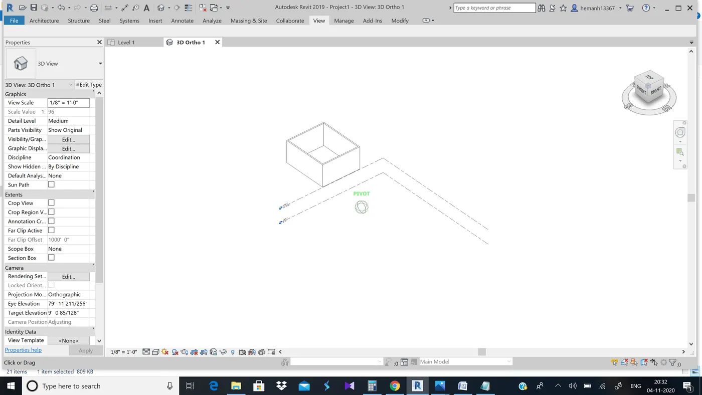
Result:-Navigatedthrought the 3D model using view cube and orbit through model layout
8th ans)
Aim:-To use the visibility setting options to switch model to shaded, realistic, hidden lines.
Tools used:-Visual style tool
Procedure:-
Step 1:-select the visual style tool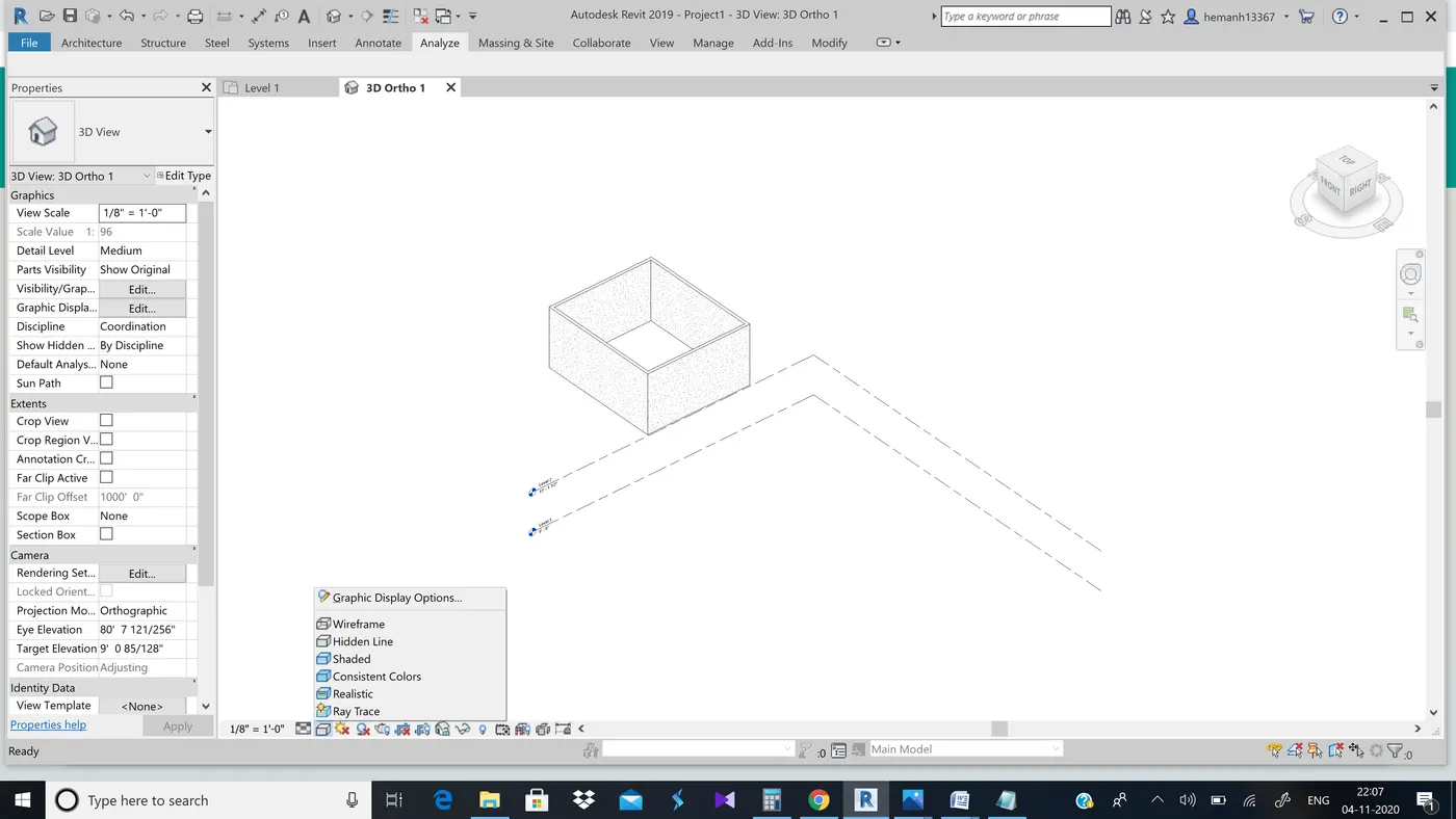
Step 2:-Now select shaded option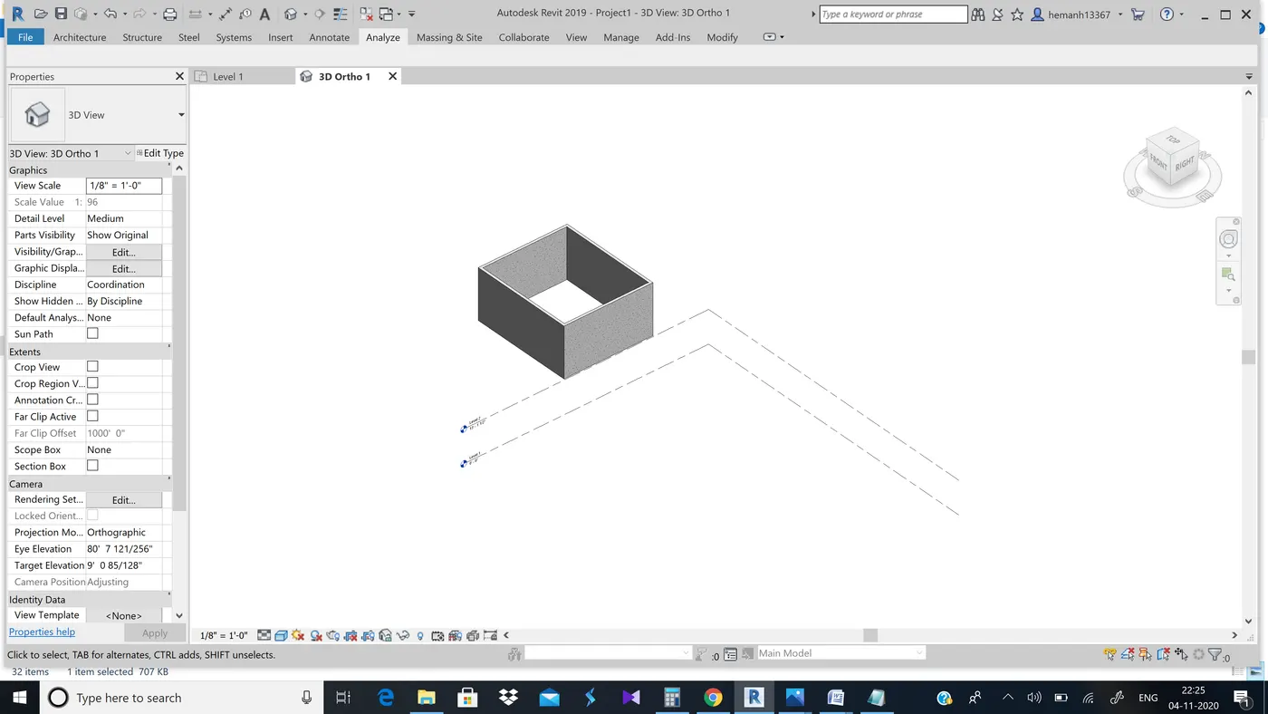
Step 3:-Now select realistic option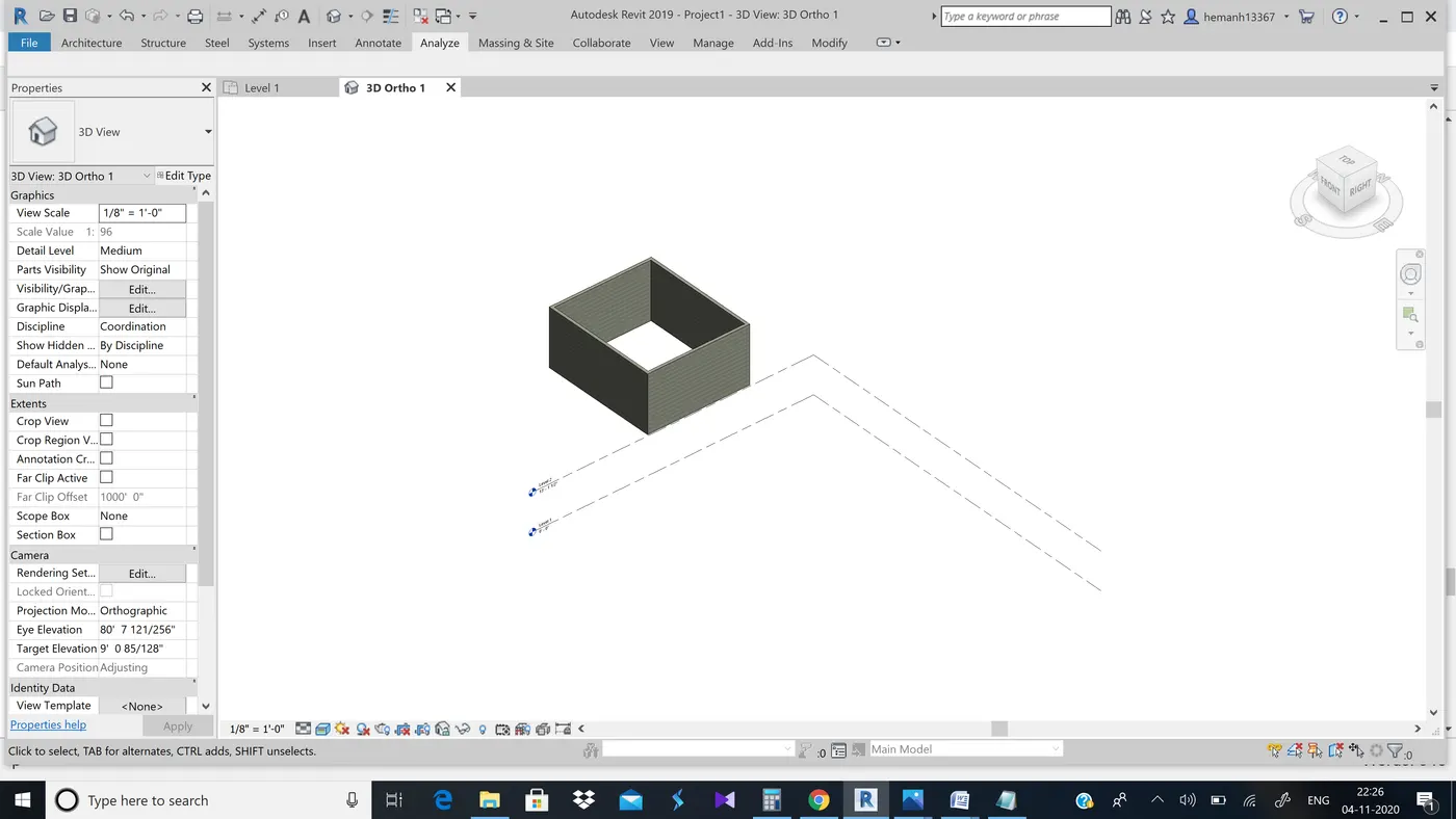
Step 4:-Now select hidden lines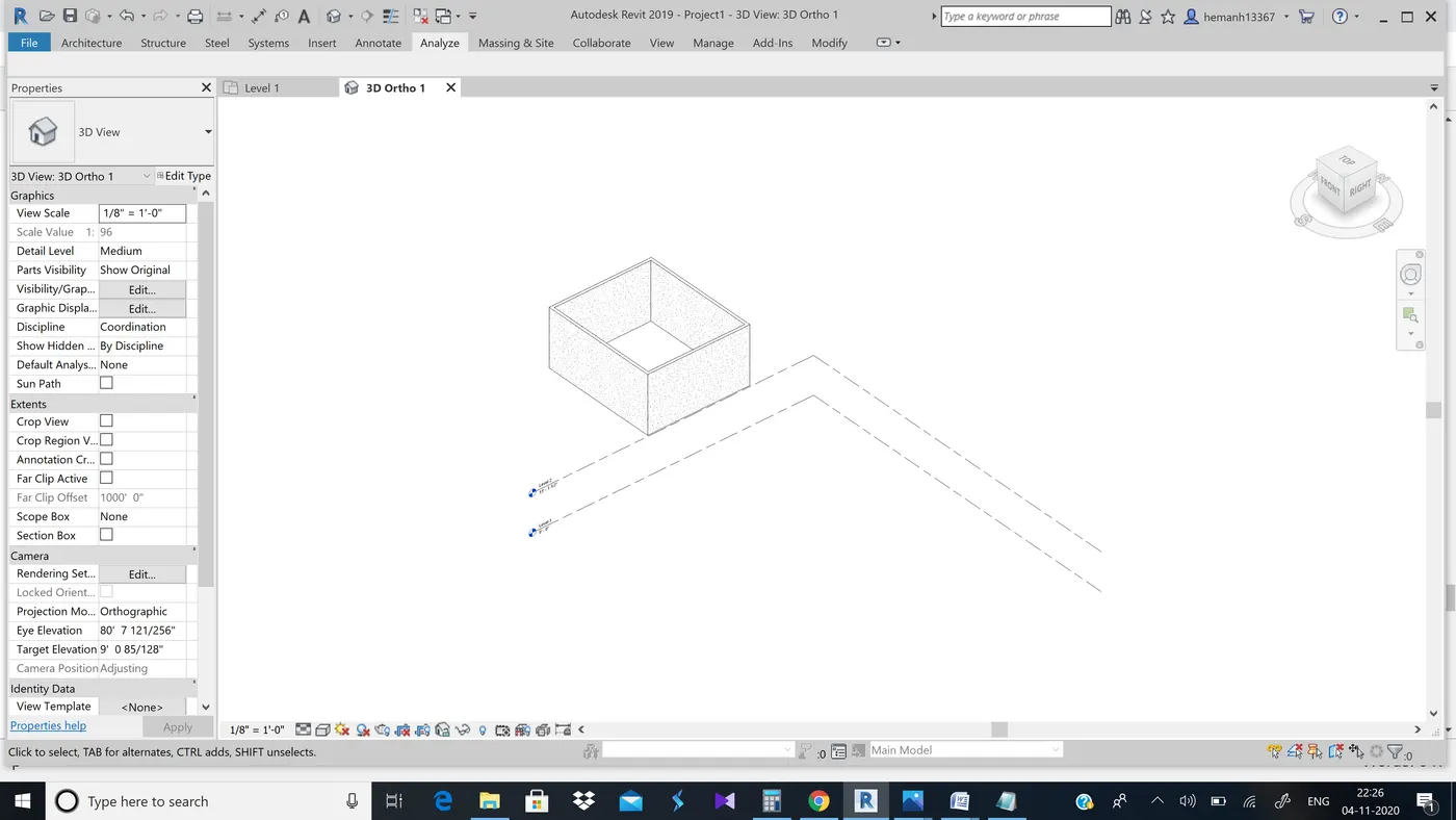
Result:-Using visiblity setting options we switched to different options
9th ans)
Aim:-To turn the sunlight on and off to view the shading in the layout created
Tools used:-sunlight tool
Procedure:-
Step 1:-Select the sunpath tool , whic is present at the bottom left of the software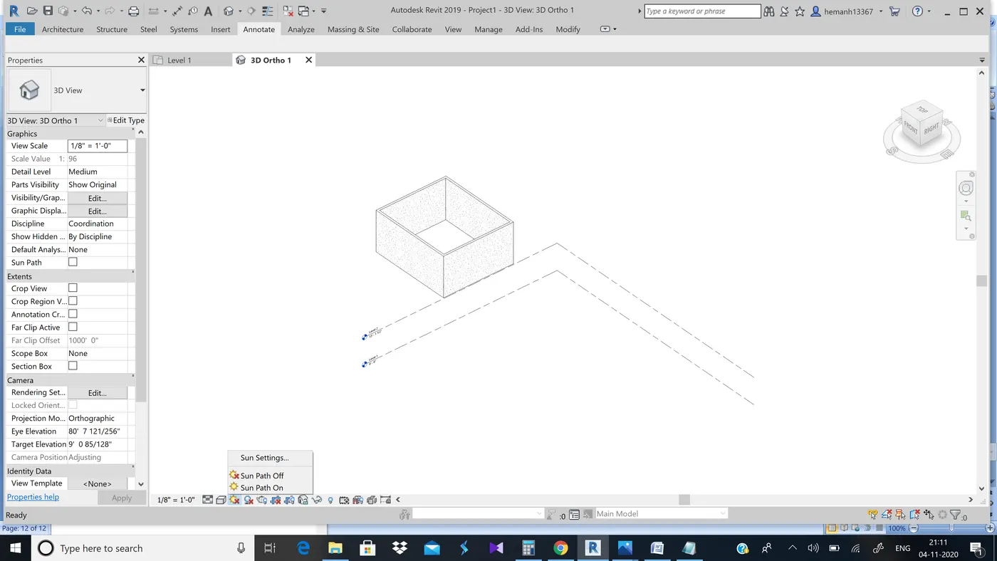
Step 2:-Now select the sun path on , now we can see the changes in layout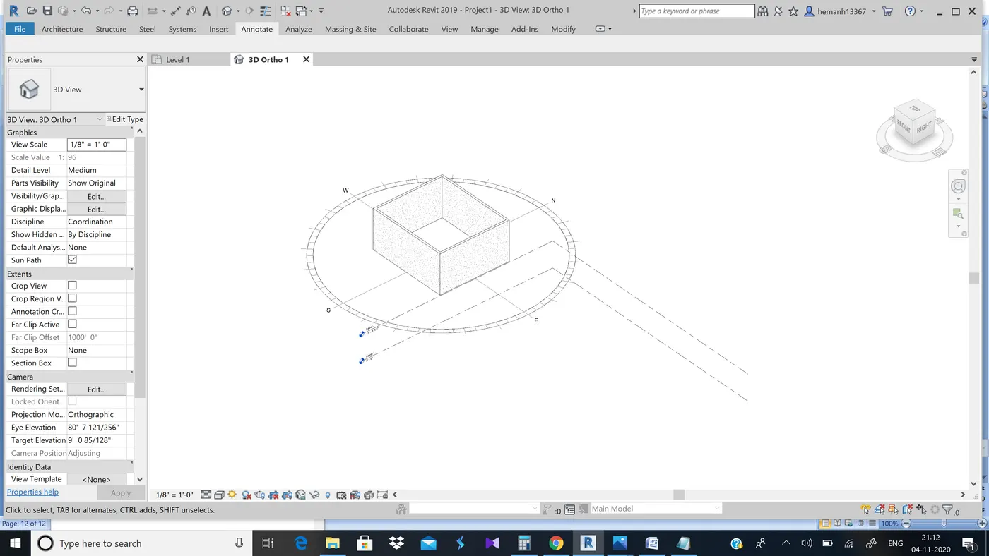
Step 3:-Now we can select the sun path off again to see the the change in shadings of the layout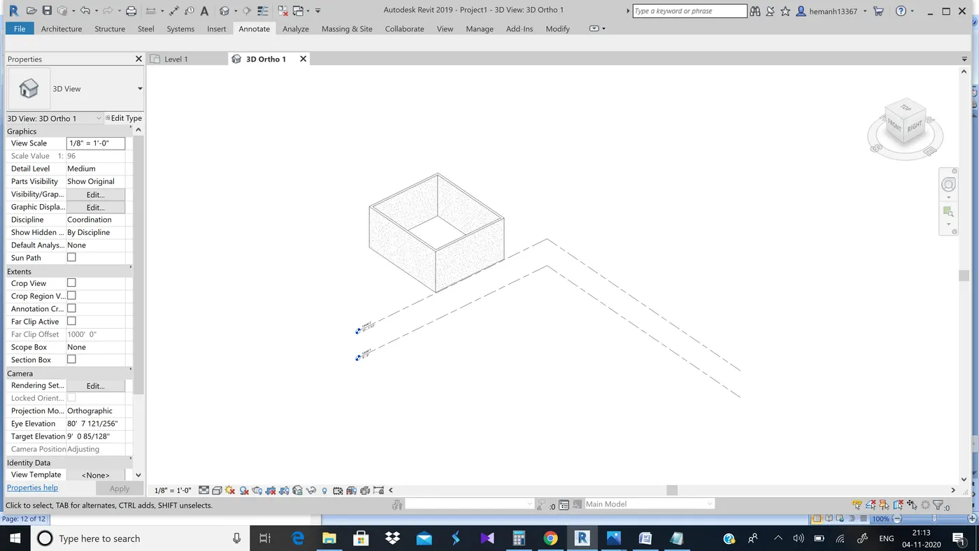
Result:-viewed the shadings in the layout created when sunlight is on and off
10th ans)
Aim:-To use the manage tool bar to enter project settings , project name and project issue date
Tools used:-Manage tool bar
Procedure:-
Step 1:-Select the Manage tool bar 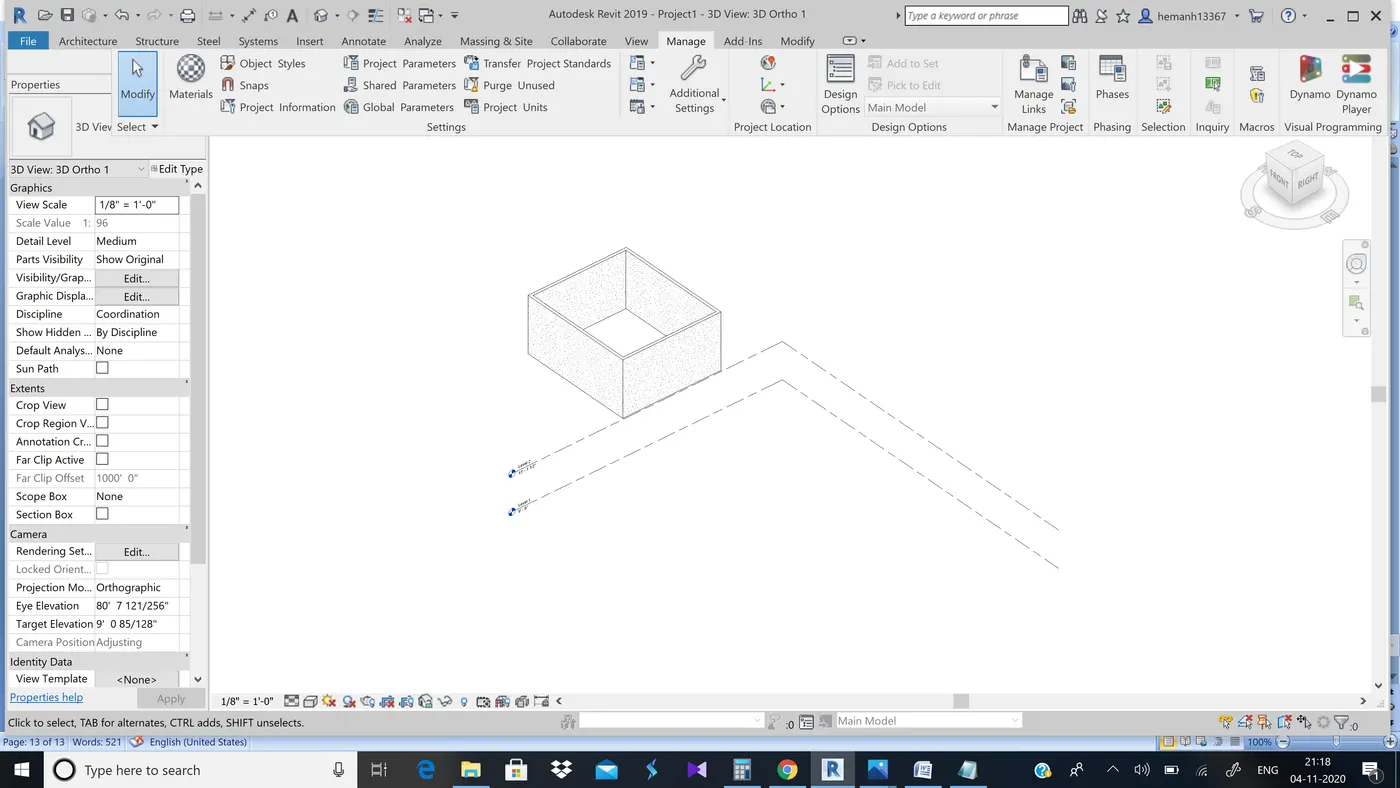
Step 2:-Now select Project information which is present beside materials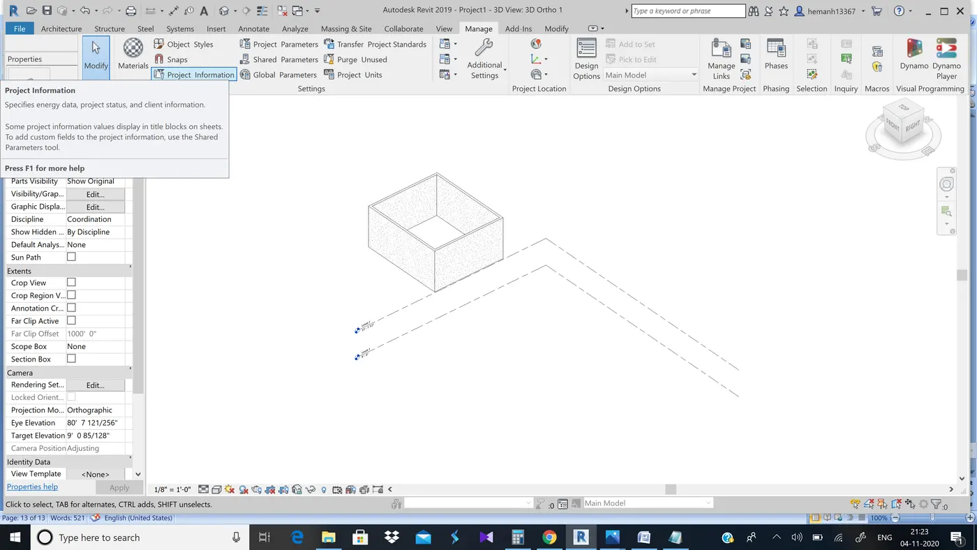
Step 3:-Now we can see a pop up where we can change the project name and project issue date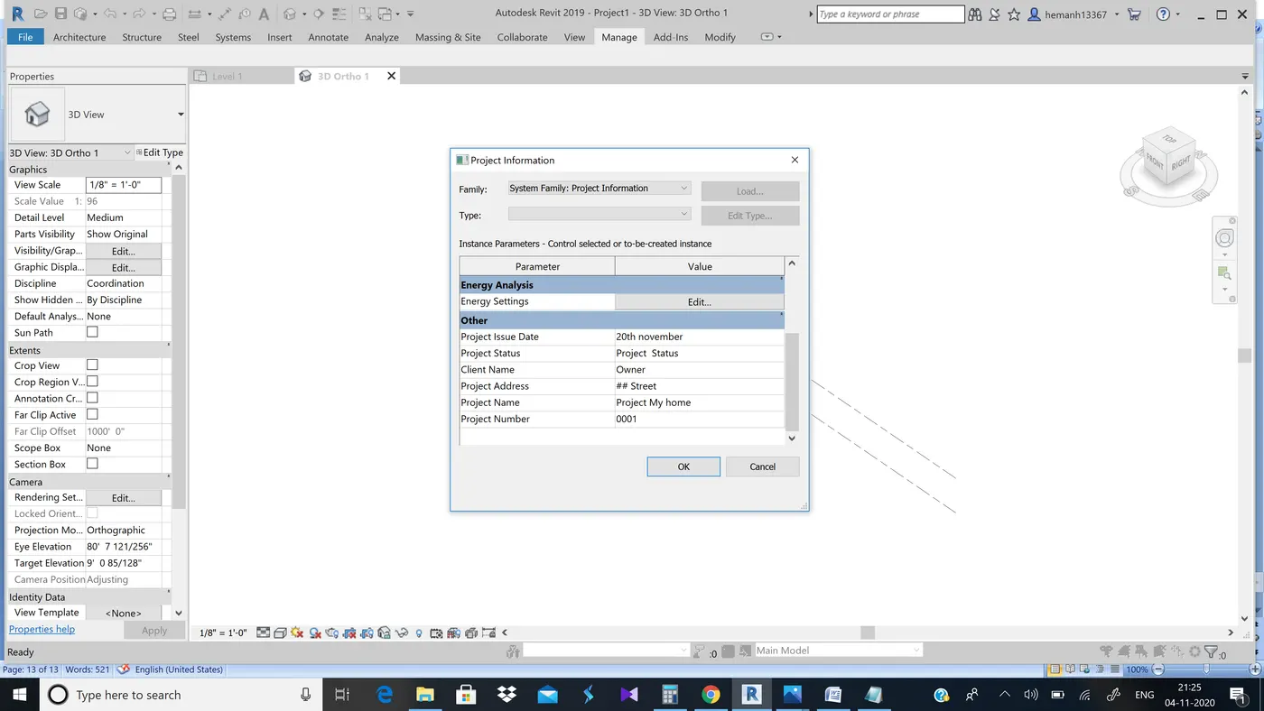
Result:-Used the manage tool bar to enter project name, project settings and project issue date
11th ans)
Analyse tool bar in revit software has wide range of uses,It has boundary conditions for analytical model,It has loads and load case adjustments and also support systems.
It also helps us to verify analytical and physical model for consistency
12th ans)
Links that support Revit to link models are:
• Link Revit: Links one revit model to the other or the current revit project.
• Link IFC: Links an IFC file to the current project for the information that is required for additional design work. • Link CAD: Links a CAD file to the present revit project.
• Link Topography: It links the existing topography to the present revit model.
• DWF Markup:It links the marked-up DWF files into the present revit project so that we can see mark-ups in the corresponding sheets. • Point Cloud: It links a point cloud file to the current revit project.
• Coordination Model:It links up a NWD or NWC file to extract content for the revit model. • Link PDF: It allows us to link the PDF file to the cu·rrent project.
• Link Image : It allows us to link an image for the progressing revit model.
• Manage links: It manages the links such as CAD, mark-up the DWF files and all the BIM works that are related to the present file.
13th ans)
Collaborate tool is used for the ease of engineers , as we all know for a project a group of engineers will be working soo this tool from revit helps us to collaborate with other engineers and we can do the required changes and get the desired project ready within time.