To calculate wind load for industrial steel structures and to apply it by using TSD
1)
Aim - To generate manual wind loading in the design report based IS code .
Procedure -
Step 1) Manual Calculation of wind loading
i) Given data-
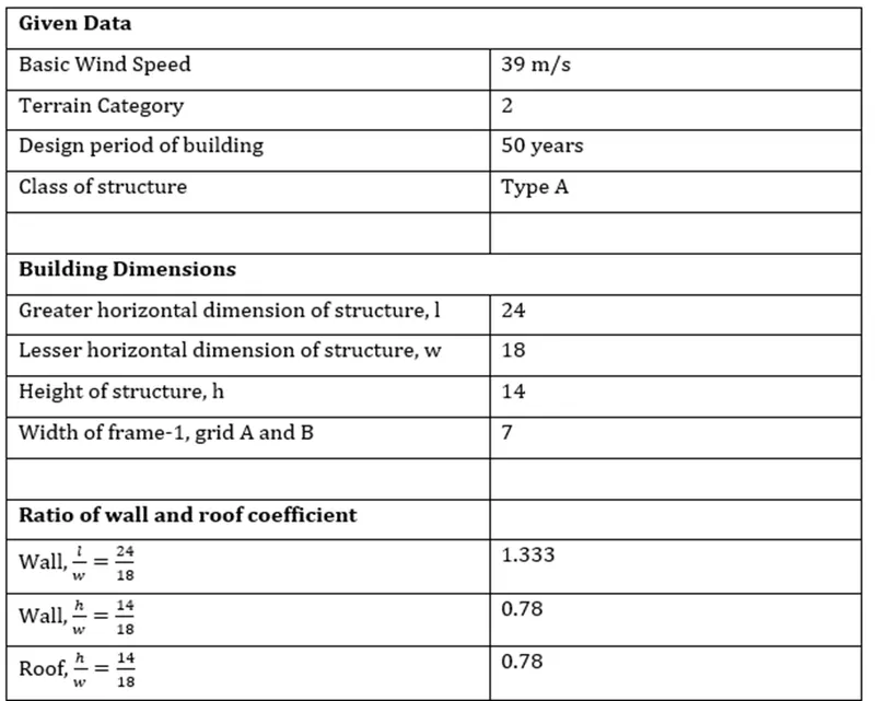
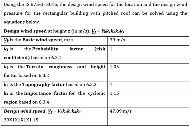
ii) Calculation Design wind Speed - Vz
iii) Calculation of Design wind pressure - Pz
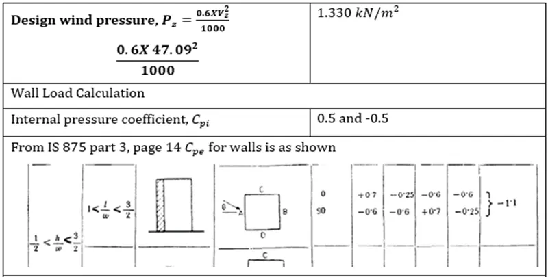
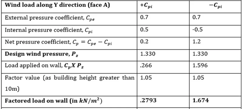
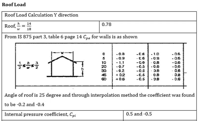
iv) Calculation of Cpe and Cpi for Face A -
v) Calculation of Cpe and Cpi for Face B -
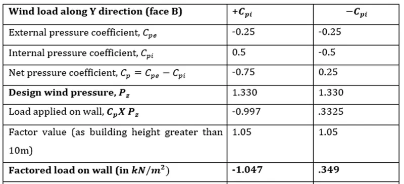
vi) Calculation of Cpe and Cpi for Face C and D -
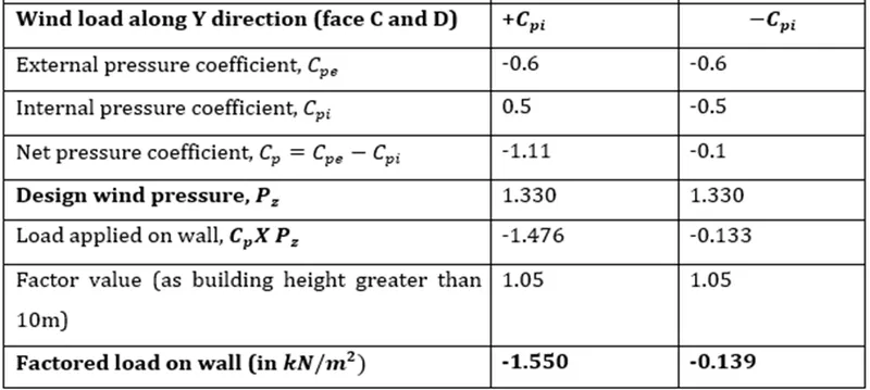
Aim - Based on the above calculation apply the loadings on the model
Step 1) Application of wind load on Model
i) Open the last week file of Tekla
ii) Click on Load cases option
iii) As we are manually applying the wind loads create the new wind load cases by clicking on add option and rename it
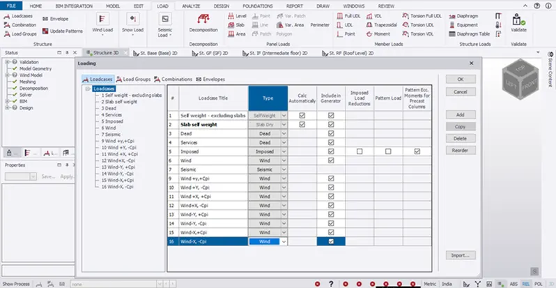
iv) Apply the wind load for 1st Case i.e Wind + Y and +Cpi
vi) The faces A, B, C and D corresponds to frame 7,3, A and D in model .
vi) The negative value of load shows that load is acting away from building and positive value shows it acts towards the building.
A ) Open Frame 7 and apply load 0.280 Kn/m^2
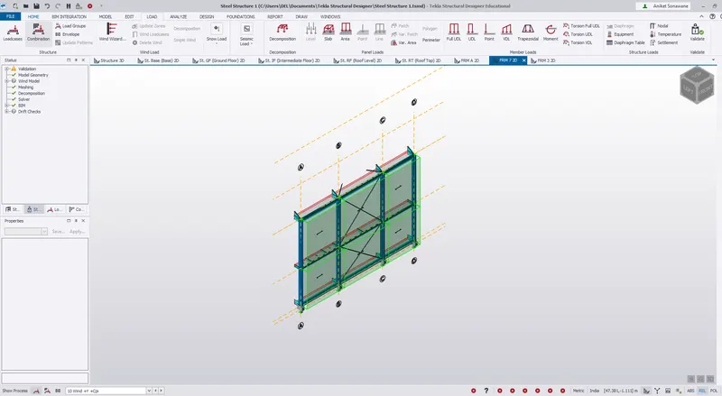
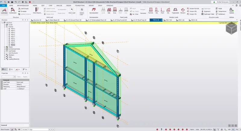
B) For Face B open Frame 3 - Load vales -1.047 Kn/m^2 ( As - sign shows that load is acting away from the stucture )
so no need to give negative valus as our axix is also going away from the structure for Frame 3 .
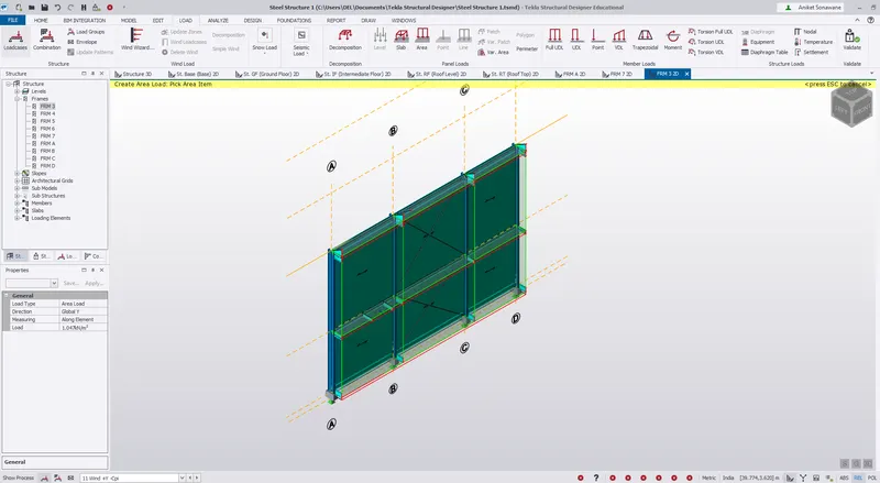
C & D) - For Face C and D open Frame A and D - Loading value is -1.550 Kn/m^2
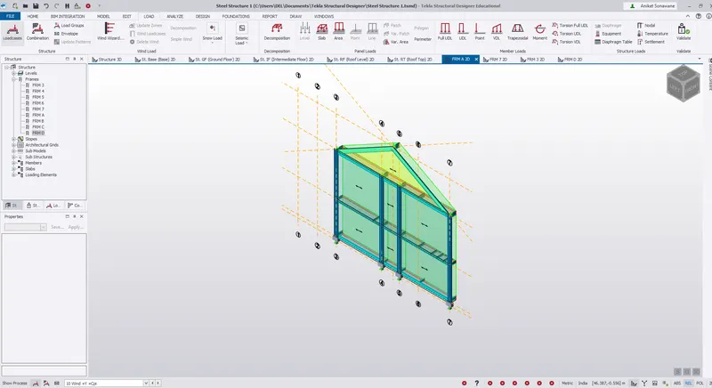
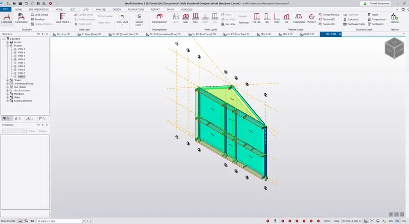
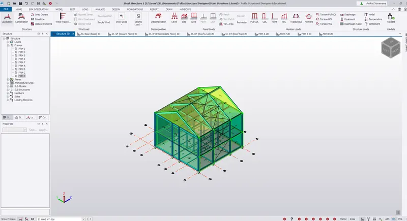
vii) 3D view of +Y +Cpi
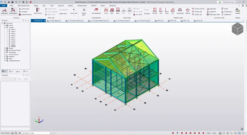
2) Now Select Load Cases = +Y -Cpi - Follow the same procedure
A ) Open Frame 7 and apply load 0.168 Kn/m^2
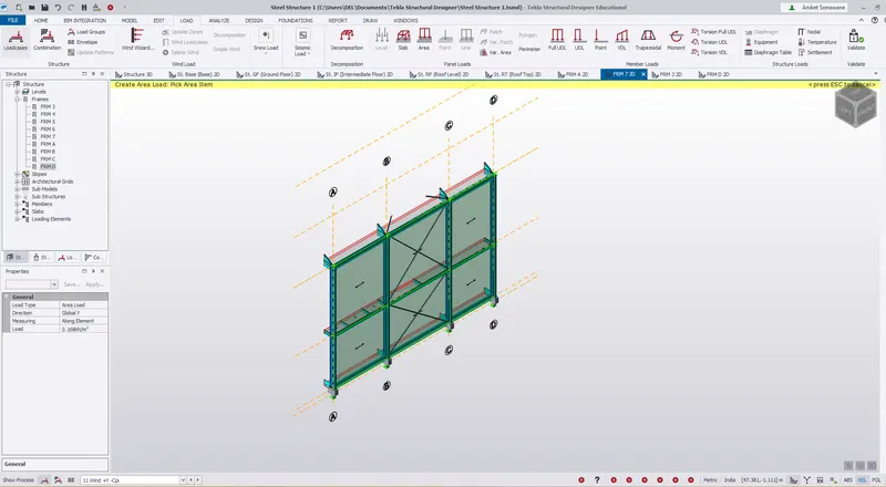
B) For Face B open Frame 3 - Load vales 0.35 Kn/m^2
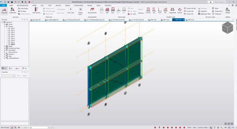
C & D) - For Face C and D open Frame A and D - Loading value is -0.14 Kn/m^2
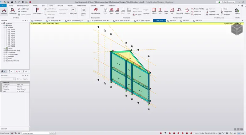
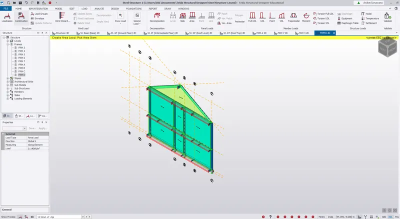
3D view - +Y -CPi
3) Load Case = -Y +Cpi
i) The only difference in this from above +Y loading is the change in direction of face.
ii) The faces A, B, C and D corresponds to frame 3, 7, D and A. Rest load application process is the same
A) Face A - Frame 3 = Loading value = 0.28 Kn/m^2
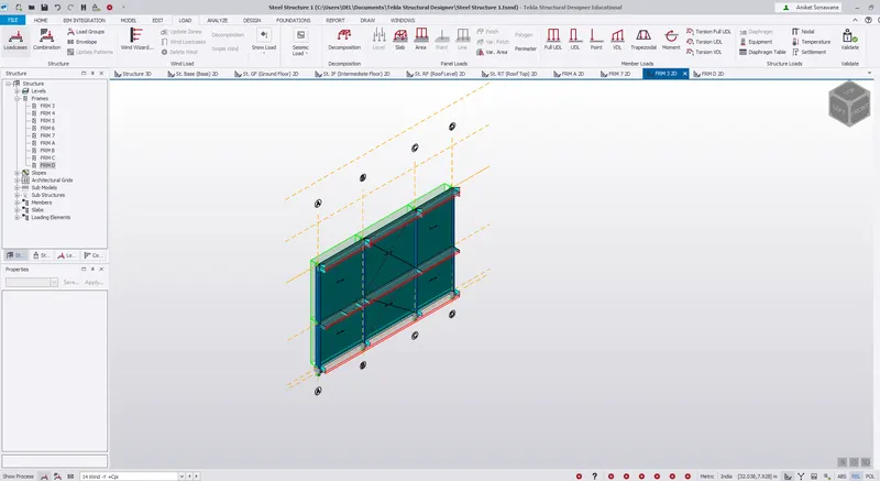
B) Face B - Frame 7 = Loading value = -1.05 Kn/m^2
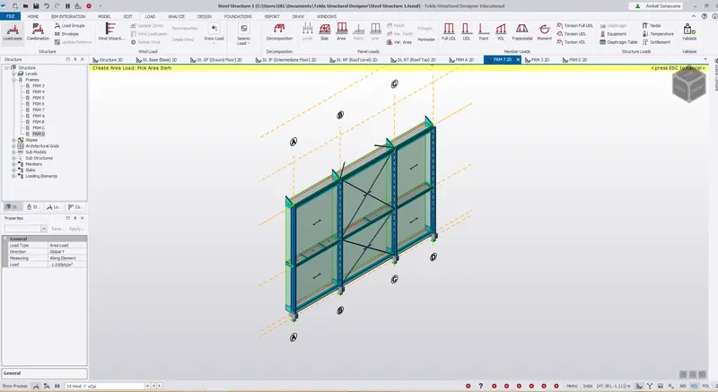
C & D ) Face C and D - Frame D and Frame A = Loading value = -1.55 Kn/m^2
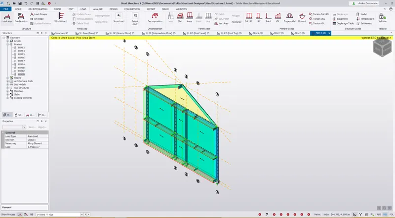
3D view of -Y +Cpi
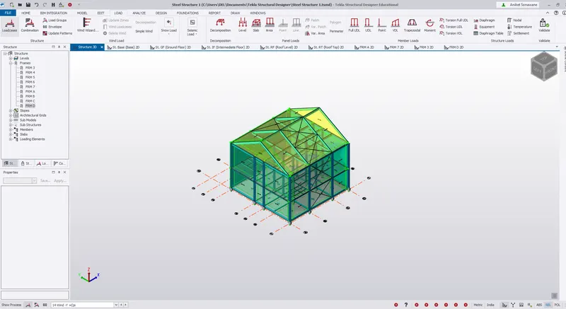
4) Load Case = -Y -Cpi
A) Face A - Frame 3 = Loading value = 1.70 Kn/m^2
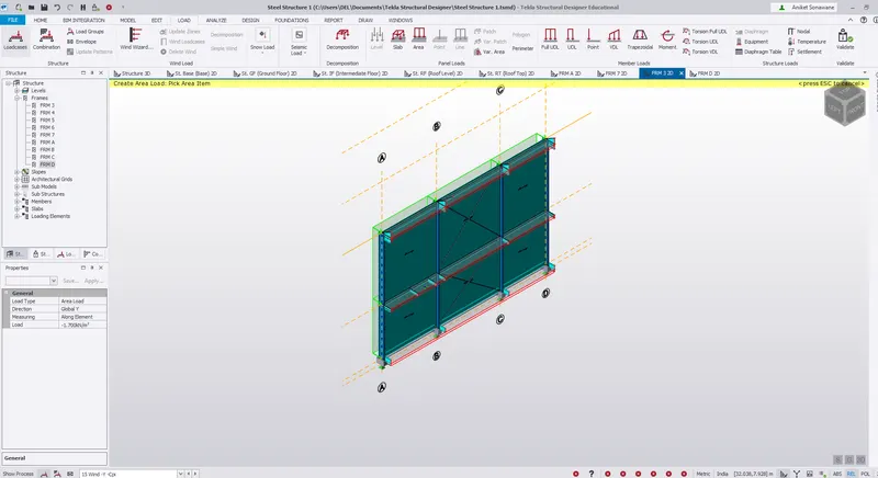
B) Face B - Frame 7 = Loading value = 0.35 Kn/m^2
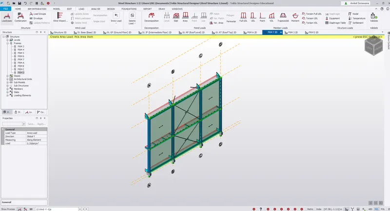
C & D ) Face C and D - Frame D and Frame A = Loading value = - 0.14 Kn/m^2
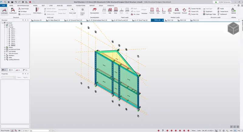
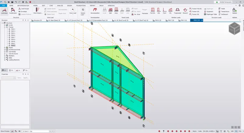
3D view = -Y -Cpi
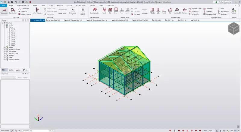
Step 3)
i) +X and -X wind loadings are calculated and applied next.
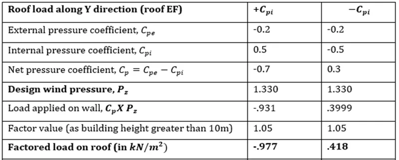
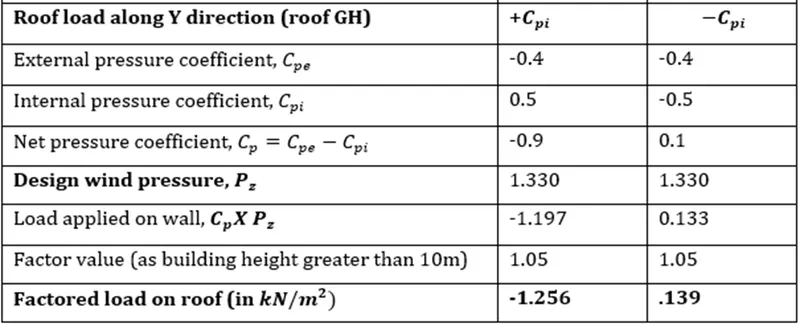
A) Load Case = +Y +Cpi
Face EF - Loading value - -0.977 Kn/m^2
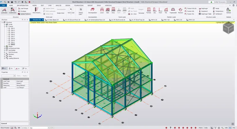
Face GH - Loading Value - -1.256 Kn/m^2
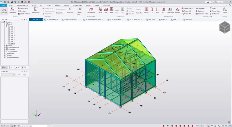
B)
Load Case = +Y -Cpi
Face EF - Loading value - 0.418 Kn/m^2
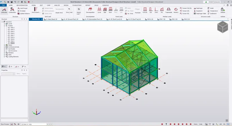
Face GH - Loading Value - 0.39 Kn/m^2
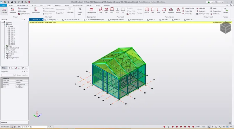
C) Load case -Y, +Cpi
Face GH - Loading Value - -0.977 Kn/m^2
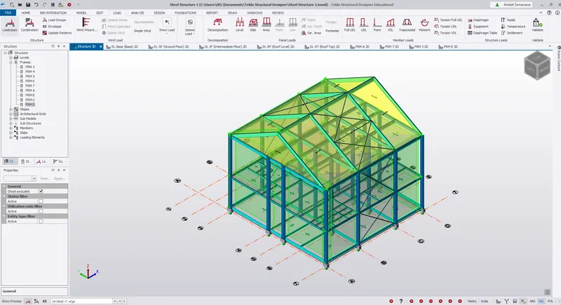
Face EF - Loading Value - -1.256 Kn/m^2
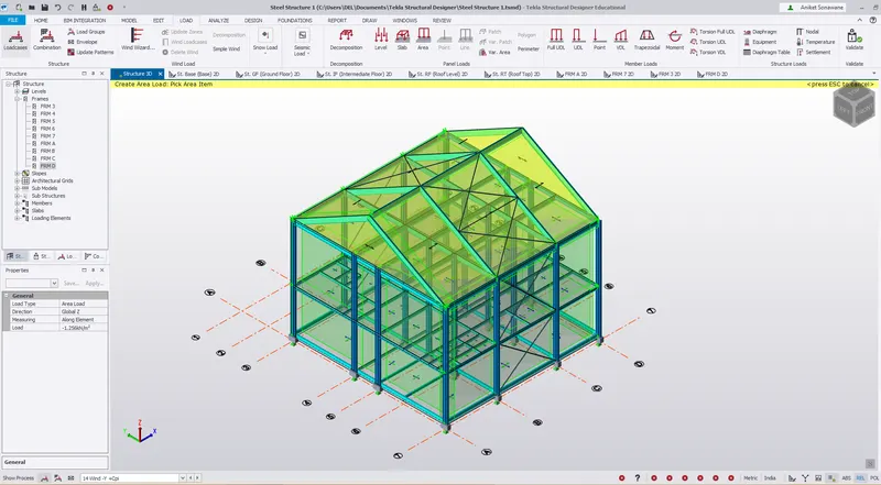
D) Load Case - -Y -Cpi
Face GH - Loading Value - 0.418 Kn/m^2
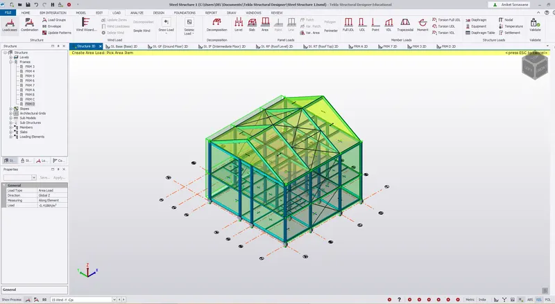
Face EF - Loading Value - 0.139 Kn/m^2
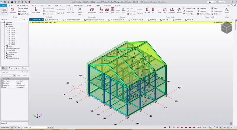
Step 4) Validation
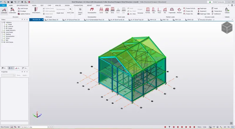
i) Validate a model
ii) No error
3)
Aim - To generate a separate model for wind loading using wind wizard .
Procedure -
i) Save as the current file .
ii) Now delete the load cases which we have define
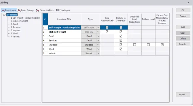
iii) Go to Load tab - Select Wind Wizard
iv) Following Dialog box will open
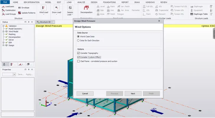
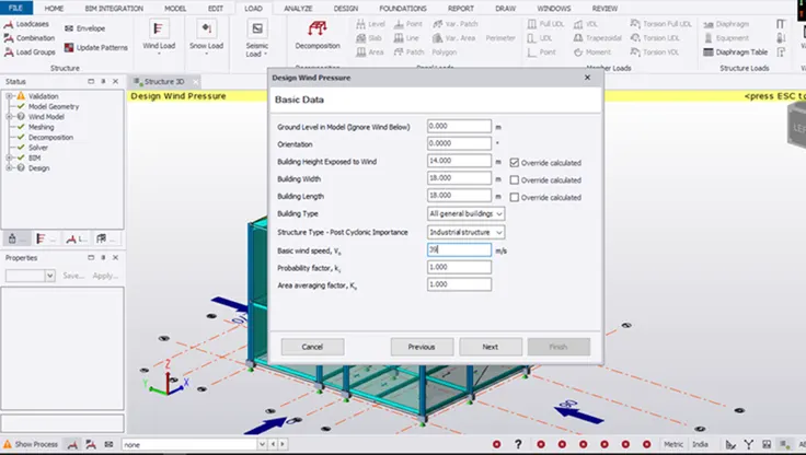
v) Enter the basic details of steel building like the dimensions, wind speed and various factors etc. and click on next.
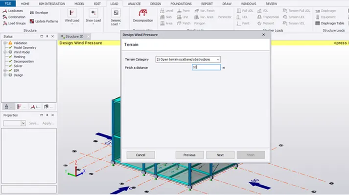
vi) Select the terrain category from the drop-down list and click next.
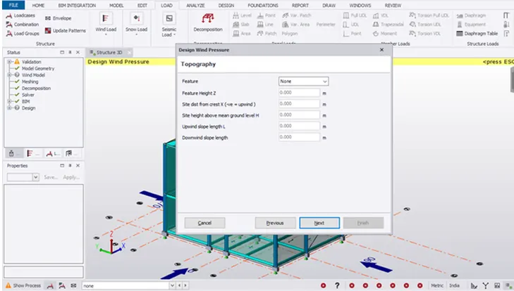
vii) In topography if needed apply the desired values and click next.
viii) Next the results will be shown as below
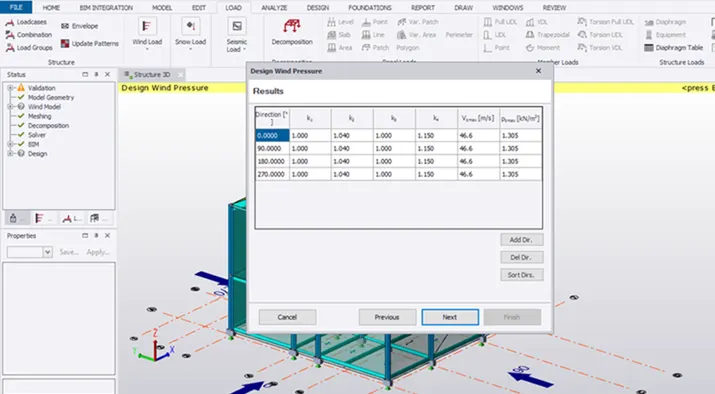
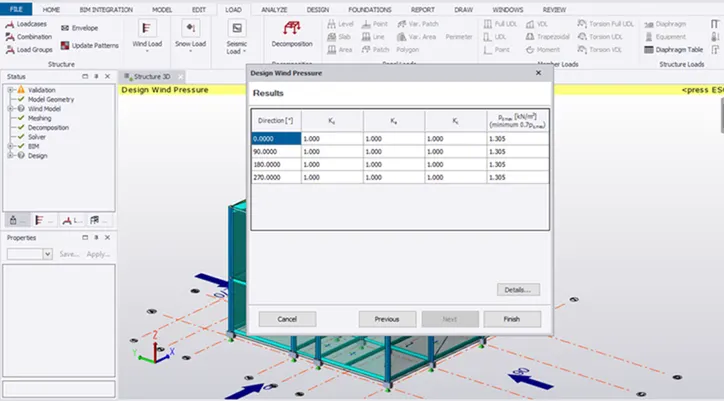
ix) Now we have to define wind load cases -
x) Go to Load - Wind Load cases
xi) Following design wind load cases dialogue box will open
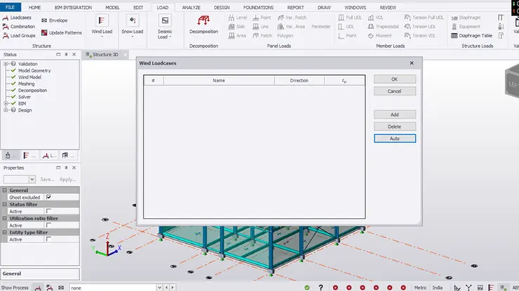
Click on Auto
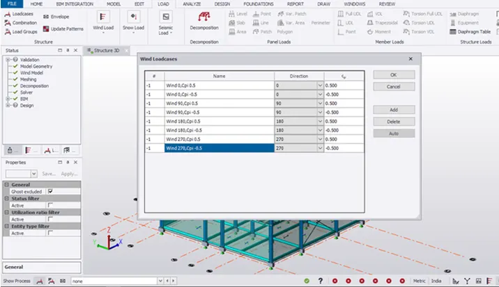
xii) Validate the model
Results -
i) Wind loads and roof loads is calculated based on IS 875 Part III.
ii) The wind load and roof load applied to the steel structure.
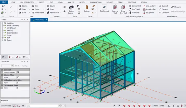
iii) A separate model is created and wind load is calculated using the Tekla software’s wind wizard