Creating a Floor plan, Footing detail and Isometric view using AutoCad
Aim - To Create Floor Plan , Footing Details and Isometric view using Autocad tools .
Introduction - i) In this assignment various tools like line , polylines , rectangle etc are going to
used to draw the cross sections of load bearing wall , isolated footing , gable wall
two bedroom building , cross section of two bedroom details .
ii) Isometric snaps are going to used in this assignment for Isometric view of
staircase .
Procedure -
A) Cross Section of load bearing wall -
Aim - To draw a cross section of load bearing wall
Introduction - For Cross section of load bearing wall following commands are used
i) Rectangle
ii) Line
iii) Trim
iv) Offset
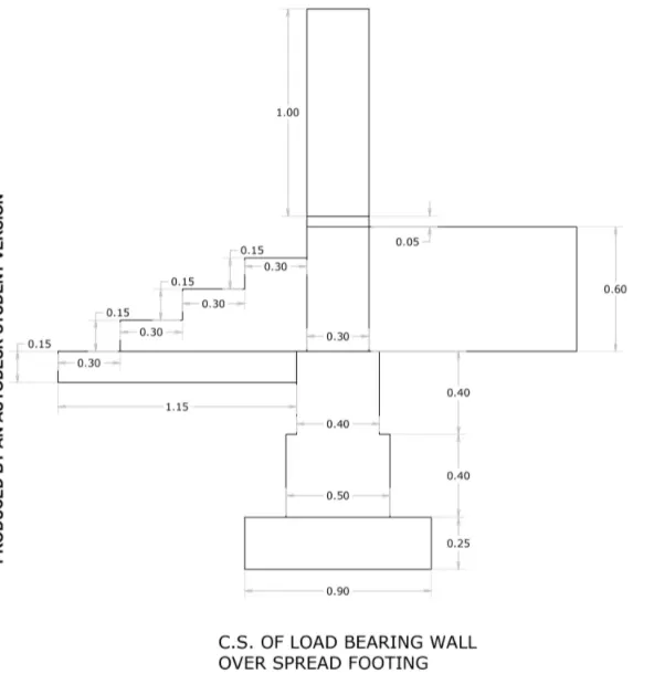
Step by Step procedure of cross section of load bearing wall -
Step 1)
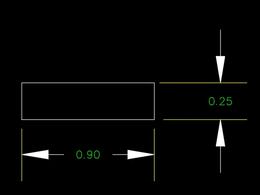
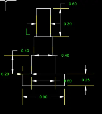
i) Create a rectangle of dimension 0.90 x 0.25 by giving command Rec / Rectangle in command line .
ii) Specify the first point as ( 1,1)
ii) Enter D for dimensions
iv) Enter Length = 0.90 units
v) Enter Width = 0.25 units
vi) Spcify the other corner
Step 2) -
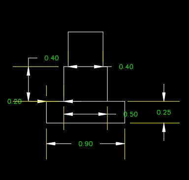
i) Give Command L in command box
ii) Specify next point (@0.20 ,0) from the 1st corner of the rectangle .
iii) Specify next point (@0 , 0.40)
iv) Specify next point (@0.05,0)
v) Specify next point (@0 , 0.40)
vi) Specify next point (@0.40 , 0)
vii) Specify next point (@0 ,- 0.40)
vii) Specify next point (@0.05,0)
viii) Specify next point (@0 ,- 0.40)
Step 3)
i) Draw a point L for reference . Give Command L( line) in Command Box
ii) Specify the point ( @0.05 ,0) considering point L .
iii) Specify the next point ( @0 ,0.60)
iv) Specify the next point ( @0.30 ,0)
v) Specify the next point ( @0 ,-0.60)
vi) Specify the next point ( @0.30 ,0)
Step 4)
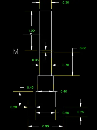
i) Draw point M for reference . Give Command oFFset ( Off) in Command Box
ii) Take the offset of point M of distance ( 0.05)
iii) Specify the next point (@0,1)
iv) Specify the next point (@0.30 ,0)
v) Specify next point ( 0, -1)
Step 5)
i) Take the Reference point L .Give Command L( line) in Command Box
ii) Specify the point (@0,-0.15)
iii) Specify the next point ( @-1.15 ,0)
iv) Specify the next point ( @0, 0.15)
v) Specify the next point ( @0.30 , 0)
vi) Specify the next point (@0,0.15)
vii) Specify the next point ( @0.30 , 0)
viii) Specify the next point (@0,0.15)
ix) Specify the next point (@0.30,0)
x) Specify the next point (@0,0.15)
xi)Specify the next point (@0.30,0)
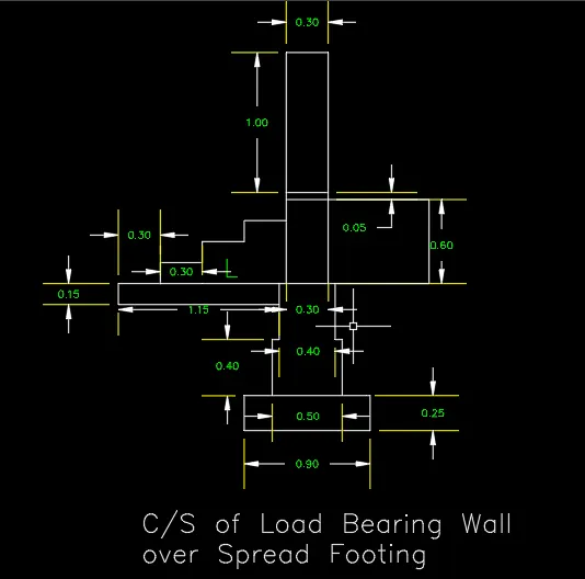
Results - The Cross Section of Load Bearing Wall over Spread footing is drawn
B) Cross Section of Isolated Footing -
Aim - To draw a cross section of Isolated Footing .
Introduction - For Cross section of Isolated Footing following commands are used
i) Line
ii) Trim
iii) Offset
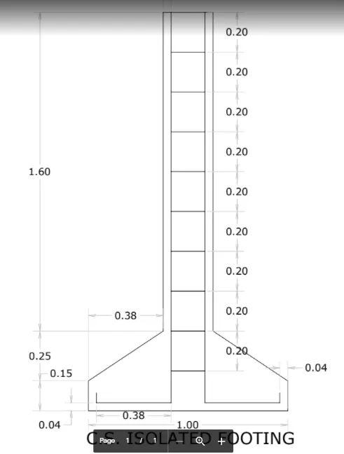
Step by Step Procedure for Isolated Footing -
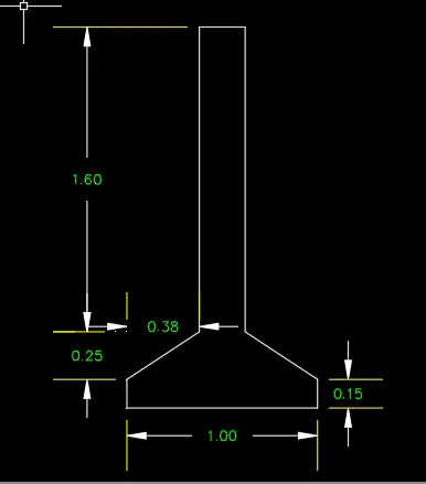
Step 1)
i) Give the command Line (L) to specify the first point (2,2)
ii) Specify the next point (1,0)
iii) Specify the point ( @0,0.15)
iv) Copy this line at a dsitance 1 to starting point .
v) Specify the next point (@0.38,0.25)
vi) Repeat this same on opposite side (@-0.38,0.25)
vii) Specify the point (@1.60 ,0)
viii) Copy this line to the opposite side
Step 2)
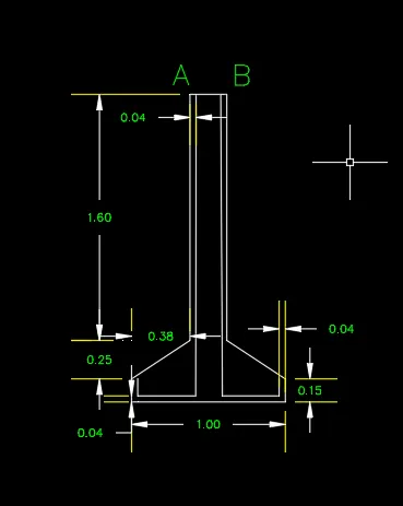
i) Draw the offset of distance ( 0.04) from reference point A to the bottom of the footing
ii) Repeat the above command for reference point B to the bottom of the line .
iii) Similarly give an offset of (0.04) for Right side of bottom and left side of Bottom .
iv) Specify the next point (@0.38,0)
v) Same for other sides (@0.38,0)
vi) Trim the unwanted lines
Step 3)
i) Draw an horizontal offset of 0.2 by giving command Offset ( O) from the reference point
A and B
ii) Trim the unwanted lines
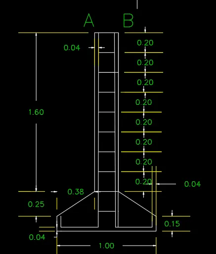
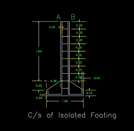
Results - Cross Section of Isolated Footing is drawn -
C) Line Diagram of Two Bedroom Building -
Aim - To draw a line diagram of two bedroom building -
Introduction - The followings commands are used to draw a line diagram of two bedroom buildin
i) Line
ii) Rectangle
iii) Offset
iv) Trim
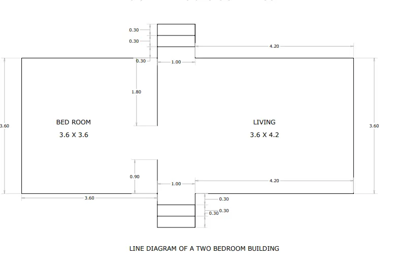
Step by Step Procedure of two bedroom building -
Step 1)
i) Draw a rectangle by giving command Rectangle / Rec .
ii) Select the dimensios
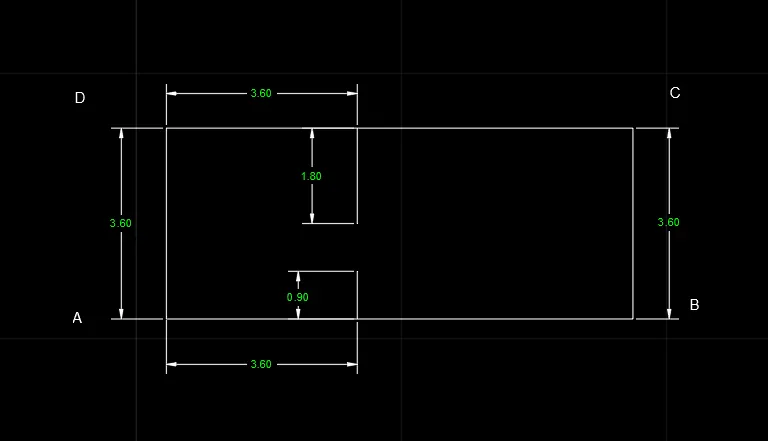
iii) Enter the Length = 8.8 units
iv) Enter the width = 3.60 units
v) Mark the points A , B , C , D
vi) Take the reference the points A and specify points ( @3.60 ,0)
vii) Specify the next points (@0,0.90)
viii) Take the reference points D and specify points (@3.60 ,0)
ix) Specify next points (@0,-1.80)
Step 2)
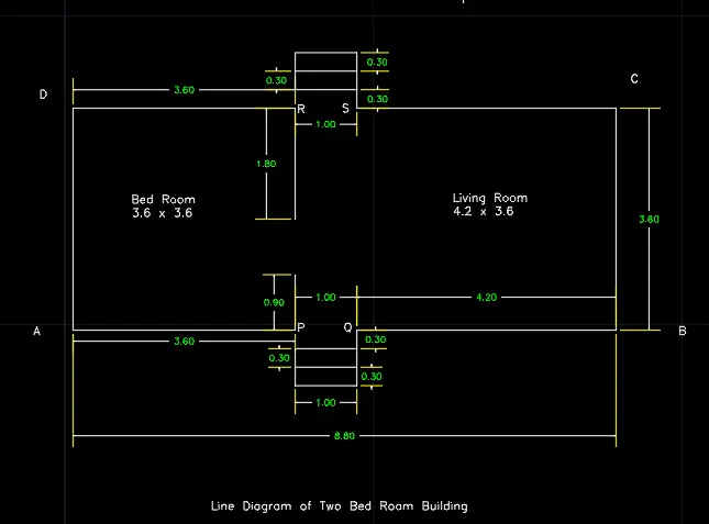
i) Draw a line PQ and RS by direct distance entry ( 1 units )
ii) Draw an offset of line PQ and RS by giving command Offset (O) of a distance 0.3 in 3 layers
iii) Trim the line PQ and RS
iv) Give the Dimension of Bed room and Living Room by using command Text (T)
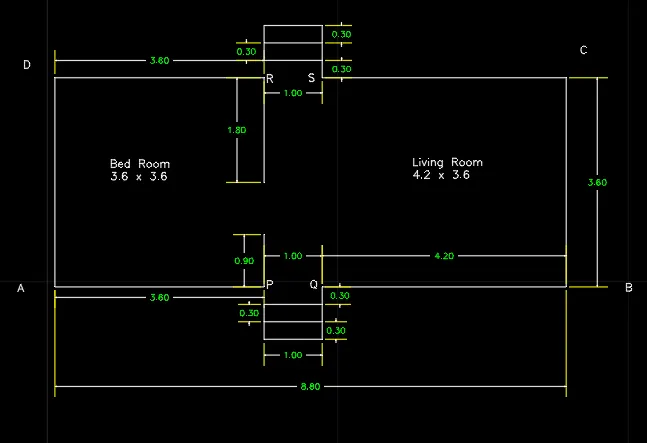
Results - Line Diagram of Two Bedroom Building is drawn
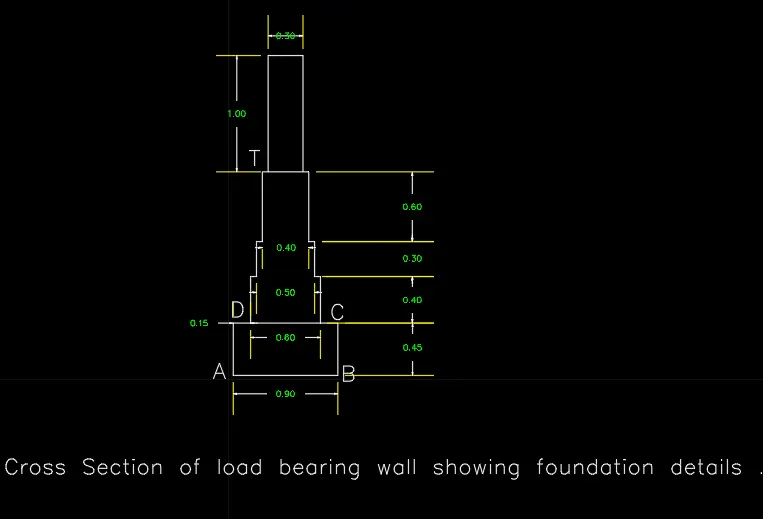
D) Cross Section of load bearing wall showing foundation details .
Aim - To draw cross section of load bearing wall showing foundation details .
Introduction- The Following commands are used to draw cross section of load bearing wall
showing foundation details .
i) Line
ii) Rectangle
iii) Trim
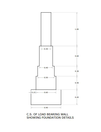
Step by Step Procedure of cross section of load bearing wall showing foundation details
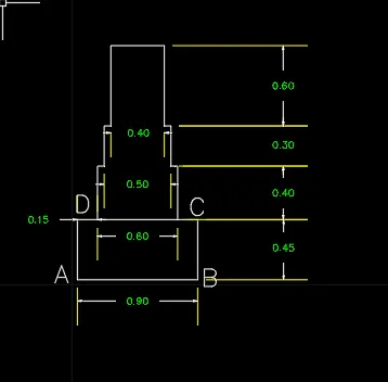
Step 1)
i) Draw a rectangle by giving command Rectangle / Rec .
ii) Select the dimensions
iii) Enter the Length = 0.90 units
iv) Enter the width = 0.45 units
v) Name the Rectangle A , B , C , D
vi) Specify the base points as D and draw the line (@0.15 ,0)
vii) Specify the next points (@0,0.40 )
viii) Specify the next point ( @0.05 ,0)
ix) Specify the next point (@0,0.30)
x) Specify the next point ( @0.05 ,0)
xi) Specify the next point ( @0 ,0.60)
xii) Specify the next point ( @0.40 ,0)
xiii) Specify the next point ( @0 ,-0.60)
xiv) Specify the next point ( @0.05 ,0)
xv) Specify the next point (@0,-0.30)
xvi) Specify the next point ( @0.05 ,0)
xvii) Specify the next point (@0,-0.40)
Step 2)
i) Take the Base point T and draw line by giving command line ( L) at (@ 0.05 , 0)
ii) Specify the next point ( @1,0)
iii) Specify the next point ( @0 , 0.30)
iv) Specify the next points ( @0 , -1)
v) Measure the Dimension by giving command by (DIM )
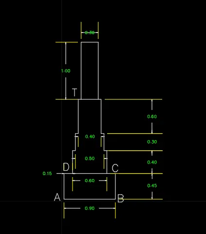
Results -Cross Section of load bearing wall showing foundation details .
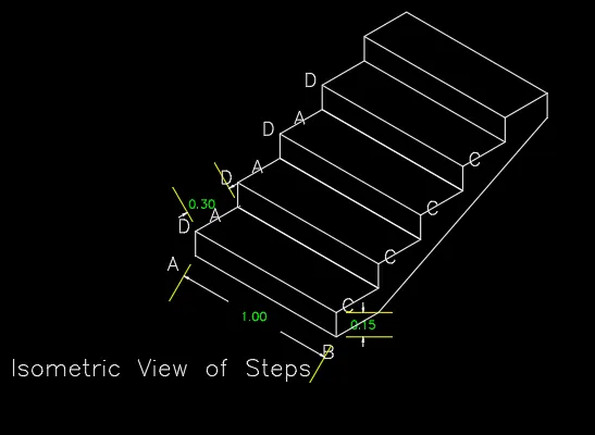
E) Isometric View of Staircase -
Aim - To draw Isometric View of Staircase
Introduction - i) Isometric view is a 3D drawing , which is set out using 30 -60-90 degrees angle
ii) To make the Isometric view on switch off the grid mode and snap mode .
iii) On the Isomteric Snap .
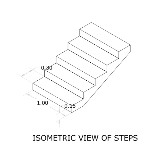
Procedure -
Step by step procedure of Isometric view of steps -
Step 1)
i) Switch off the grid and snap mode.
ii) Turn on the Isometric snap
iii) Make sure that Orthomode is on
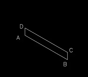
iv) Give the command L and make the cursor to +ve y direction and enter 0.15 units
v) Click F5 to change the Isoplane and make it on Left side
vi) Make the cursor on -x direction and enter 1 units
vii) Copy the 1 unit line by giving command (Co)at a distance 0.15 units to +ve y directions
viii) Similarly Copy the 0.15 unit line to -ve x direction at a distance of 1 units
Step 2)
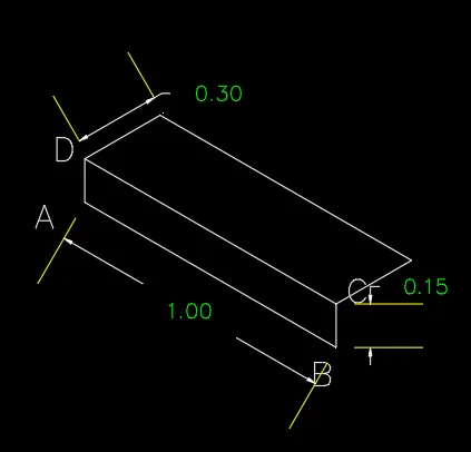
i) Take the reference point C make the Isoplane right (F5) and enter 0.30 units
ii) Copy this to the reference point D .
iii) Join this line by giving command Line (L)
Step 3)
i) Copy the whole object by giving command (CO)
ii) Switch off the Orthomode and turn on the Isoplane right
iii) Copy the whole object in 4 layers .
iv) Turn on the Isoplane rights and joins the two ends .
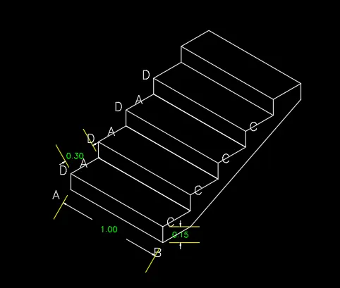
Results - Isomteric view of Steps is drawn .
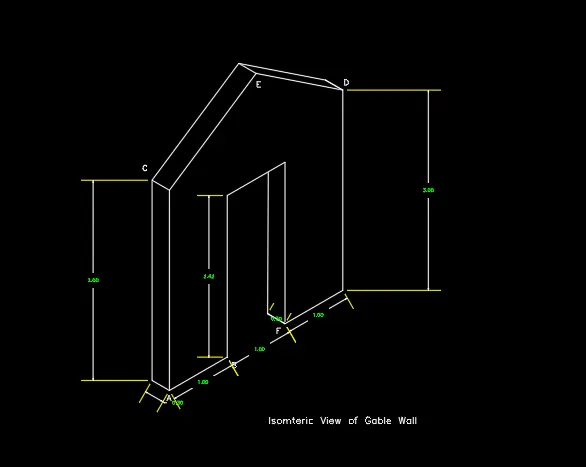
F) Isomteric View of Gable wall -
Aim - To draw a Isomteric view of Gable wall
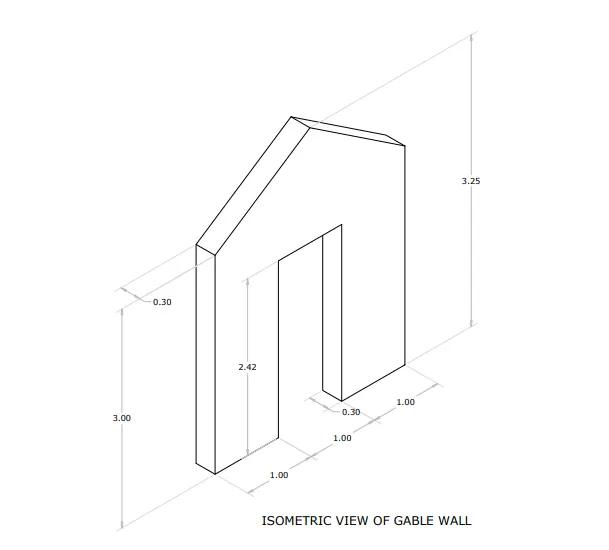
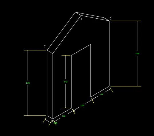
Step by Step Procedure of Isometric view of Gable wall
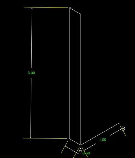
Step 1)
i) Switch off the grid and snap mode.
ii) Turn on the Isometric snap
iii) Make sure that Orthomode is on
iv) Take the reference point A and B
v) Give the command L and make the cursor to +ve x direction of A and enter 1 units .
vi) Specify next point by keeping the cursr up and selecting Isoplane top and enter 3 units in
+ve y directions .
vii) Give the command L and make the cursor -ve x direction of A and enter 0.30 units
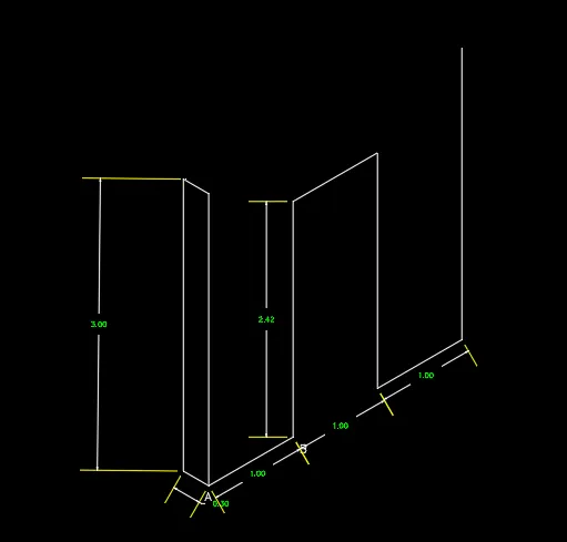
Step 2)
i) Take the reference point B
ii) Make the Isoplane top and enter the 2.42 units
iii) Make the Isoplane right and make the cursor +ve x direction and enter 1 units
iv) Make the Isoplane top and make the cursor -ve y direction and enter 2.42 units
v) Make the Isoplane right and make the cursor +ve x direction and enter 1 units .
vi) Make the Isoplane top and make the cursor +ve y direction and enter 3 units.
Step 3)
i) Take the mid point of bottom line i.e 1.5 unit
ii) Make the Isoplane top and make the cursor in +ve y direction and enter 4 units ( 3.25 is not
correcrt i.e given in drawing) name it as E point
iii) Take the Referemce point C and D draw the line and joint the line to the E points .
iv) Trim the unnecessary lines .
Step 4)
i) Take the reference points F.
ii) Draw the offset by giving command (O) of a distance 0.30 by keeping the cursor -x direction
make the Isoplane left .
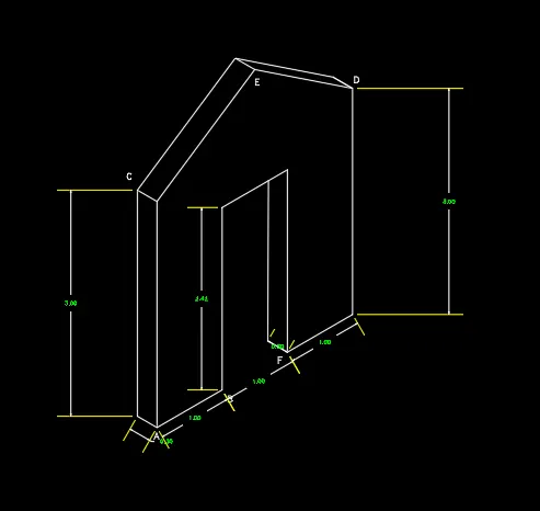
Result - Isomteric View of Gable wall is drawn