Drafting of various geometries using Chamfer, Fillet tool in AutoCad
Aim - To draw a given sketches in autocad by using various tools like Chamfer , Fillet etc .
Introduction - i) In autocad there are various tools like Chamfer , Fillet , Trim , Rotates etc
ii) With the help of theses tools we can draw the geometries .
iii) Commands used -
a) Line
b) Rectangle
c) Offset
d) Circle
e) Chamfer and Fillet .
Procedure -
1) By using Decimal units
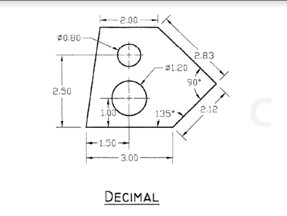
Step by step procedure to draw above geometry -
Step 1)
i) Open the New drawing sheet (Cntrl + N)
ii) Change the units - Decimals
iii) Precision - 0.00 and meter
iv) Give the command Line ( L)
v) Specify any points for eg .(2,2)
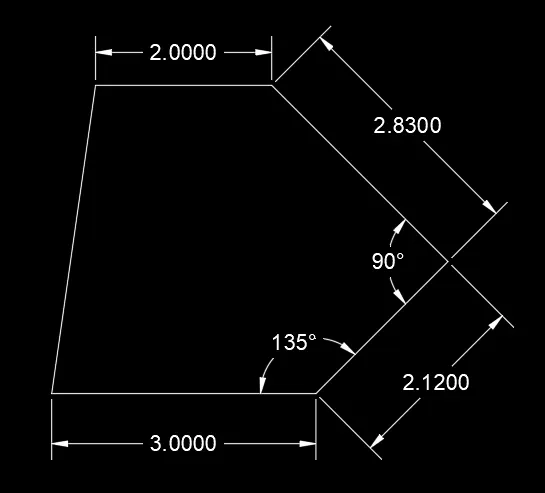
vi) Specify next points (@3,0)
vii) Specify next point (@2.12<135) . Make sure that polar tracking is on
viii) Specify next point (@2.83<90) Make sure you change the direction of angle .
ix) Specify next point (@-2.00 ,0)
x) and close .
Step 2)
i) Give the command offset .
ii) Select the base line (i.e 3 unit )
iii) GIve the offset of 1m and 2.50 m in +ve Y directions .
iv) From the midpoint of the base line (i.e 3 units ) draw a vertical line to get the center of
circle .
v) Give the command Circle ( C) .
vii) Draw 1st circle of diameter 1.20
viii) Draw 2nd circle of diameter 0.80
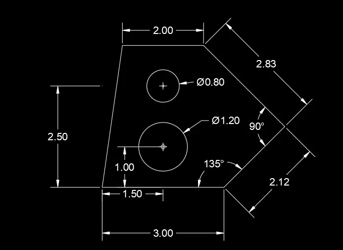
Result - Geometry of given sketch is drawn with Decimal units
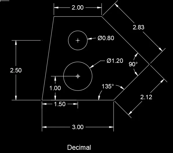
2) Aim - Draw the given sketch by using Architectural units .
Introduction - The following commands are used -
i) Line
ii) Offset
iii) Trim
Procedure - For Architectural units
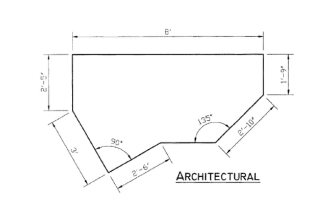
Step by step procedure to draw above geometry by using Architectural units.
Step 1)
i) Open the New drawing sheet (Cntrl + N)
ii) Change the units - Architecturals
iii) Precision - 0.00 and inches
iv) Give the command Line ( L)
v) Specify any points for eg .(2,2)
vi) Give the command LINE (LN)
vii) Specify the base points for eg (1,1)
viii) Specify the first point (@2'6'' <30)
ix) Specify next point from base point (@3<120)
x) Specify next point (@2'5"<90)
xi) Specify next point (@8'<0)
xii) Specify next point (@-1'9"<270)
xiii) Specify next point ( 2'10"<225)
xiv) Close the line .
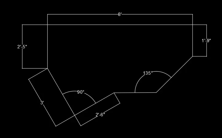
Result - Given sketch is drawn by using Architectural units .
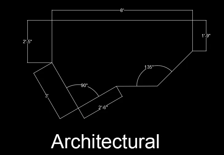
3) Aim - Draw the given sketch by using Engineering units .
Introduction - The following commands are used -
i) Line
ii) Circle
iii) Offset
iv) Trim
Procedure - For Engineering Units
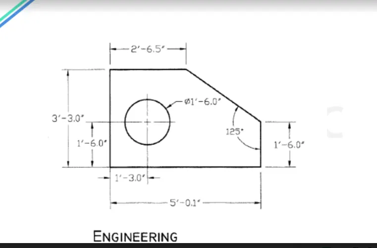
Step by Step procedure of given sketch by using Engineering units
Step 1)
i) Open the New drawing sheet (Cntrl + N)
ii) Change the units - Engineering
iii) Precision - 0.00 and inches
iv) Give the command Line ( L)
v) Specify any points for eg .(2,2)
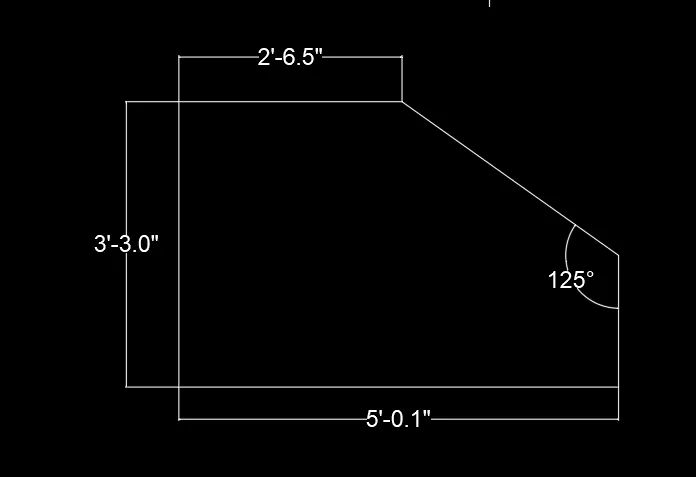
vi) Specify next point (@5'-0.1"<0)
vii) Specify next point (@1'-6.0"<90)
viii)Specify next point from base point (@3'-3.0"<90)
ix) Specify next point (@2'-6.5"<0)
x) Join the edges from both sides .
Step 2)
i) Give the command LN.
ii) Take the base point as a reference and give next point (@1'-3"<0)
iii) Take same base point and specify next point (@1'-6"<90)
iv) From theses points will get a center of circle
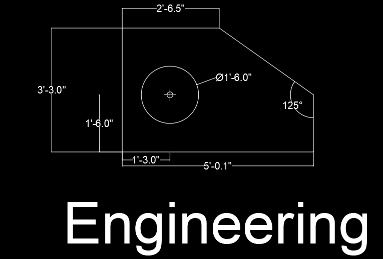
v) Draw the circle of diameter ( 1'-6")
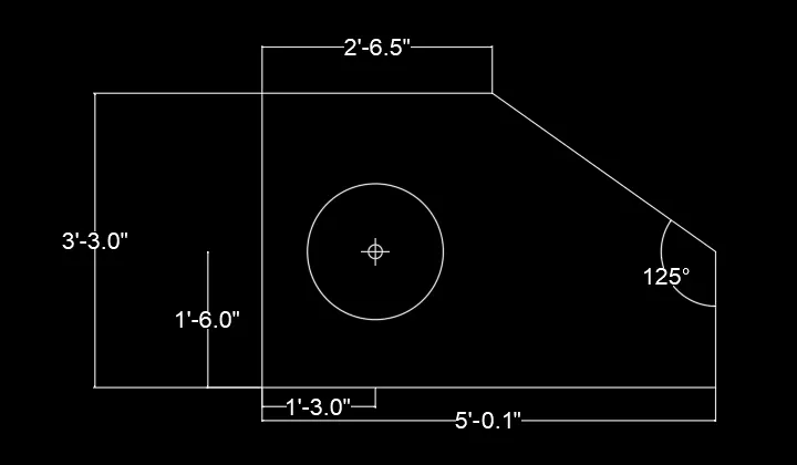
Result - Given sketch is drawn by using Engineering units .
4) Aim - Draw the given sketch by using Decimal units
Introduction - The following commands are used -
i) Line
ii) Circle
iii) Offset
iv) Trim
Procedure -
Step by step procedure of given sketches -
Step 1)
i) Open the New drawing sheet (Cntrl + N)
ii) Change the units - Decimals
iii) Precision - 0.00 and meter
iv) Give the command Line ( L)
v) Specify any points for eg .(2,2)
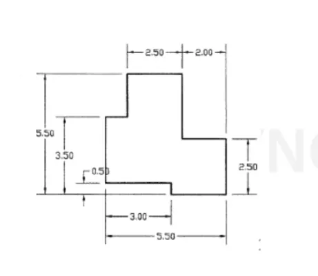
vi) Specify next points (@3,0)
vii) Specify next points ( @0,-0.50)
viii) Specify next points (@2.5 ,0 )
ix) Specify next points (@0 ,2.50 )
x) Specify next points (@-2.00 ,0 )
xi) Specify next points (@0,3 )
xii) Specify next points (@-2.5 ,0 )
xiii)Specify next points (@0 ,-2.0 )
xiv) Specify next points (@-1 ,0 )
xv) Close the line .
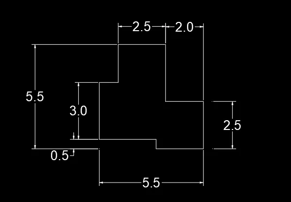
Results - Given geometry is drawn by using decimal units
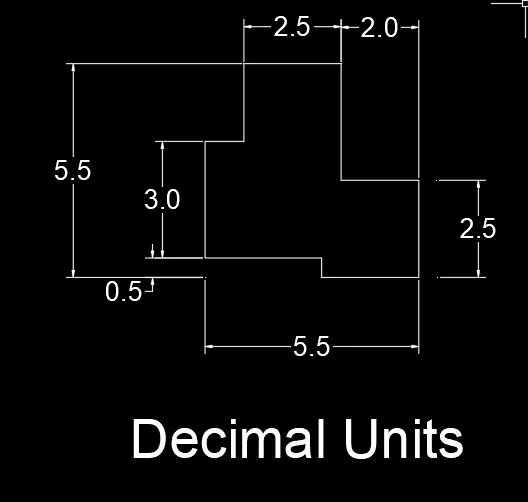
5) Aim - Draw the given sketch by using Decimal units
Introduction - The following commands are used -
i) Line
ii) Circle
iii) Offset
iv) Trim
Procedure -
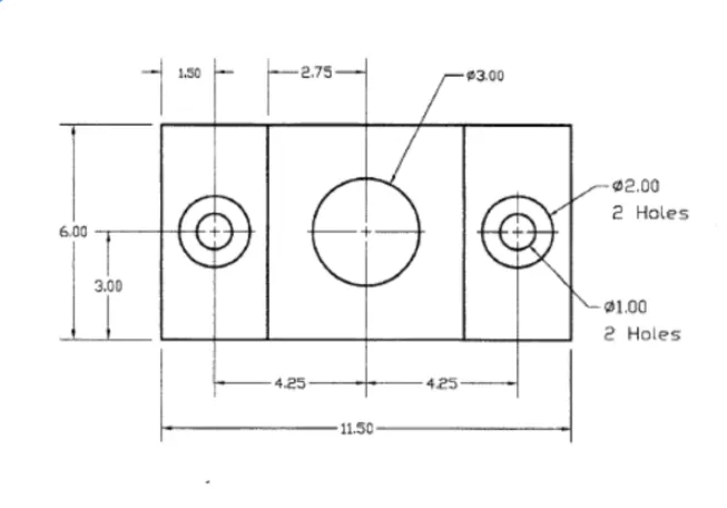
Step by step procedure of given sketches -
Step 1)
i) Open the New drawing sheet (Cntrl + N)
ii) Change the units - Decimals
iii) Precision - 0.00 and meter
iv) Give the command Line ( L)
v) Specify any points for eg .(2,2)
vi) Give command Rectangle ( Rec)
vii) Enter length = 3 units
viii) Enter width= 6 units
ix) Given command Rectangle ( Rec) and take reference points A
x) Select the reference points A
x) Enter length = 5.5 units
xi) Enter width= 6 units
xii) Take the reference point B and again draw the rectangle same as 1st rectangle .
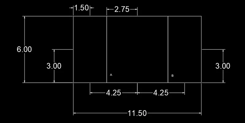
Step 2)
i) Give the command Circle (C)
ii) Draw the circle in 1st rectangle of diameter =2 units
iii) Draw the one more circle by taking same center and diameter = 1 units
iv) Make sure that your object snap is on where directly you will get cursor of circle .
v) Again give command Circle (C)
vi) Draw the circle in 2nd rectangle of diameter = 3 units
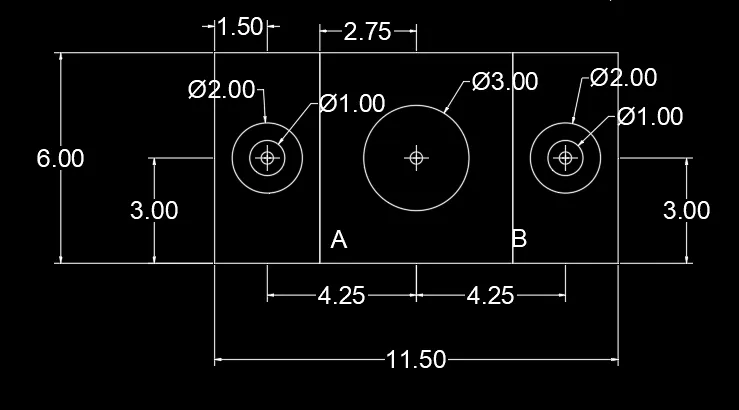
Results - Given geometry is drawn by decimal units
6) Aim - Draw the given sketch by using Decimal units
Introduction - The following commands are used -
i) Line
ii) Rotate
iii) Rectangle
iv) Copy
v) Lengthen
Procedure -
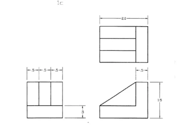
Step by step procedure of given sketches
Step 1)
i) Open the New drawing sheet (Cntrl + N)
ii) Change the units - Decimals
iii) Precision - 0.00 and meter
iv) Give the command Rectangle ( Rec)
v) Enter the length = 1.5
vi) Enter the width = 0.5
vii) Mirror the object at 90 degree
viii) Break the line of rectangle using command (Br) so that will get two individual rectangle .
ix) Copy the mirror rectangle in 2 parts by giving command (Co).
For 2nd diagram .
xi) Copy the 1st diagram .
xii) Command Erase (E) the two vertical rectangle such that will get L shape .
xiii) Command Mirror (Mr) the object and join the edges .
For 3rd Diagram
xiv) Command copy (CO)
xv) Copy the 1st diagram and rotate it by 90
xvi) Command Lengthen select delta and enter 0.5 units to get total length of 2 units .
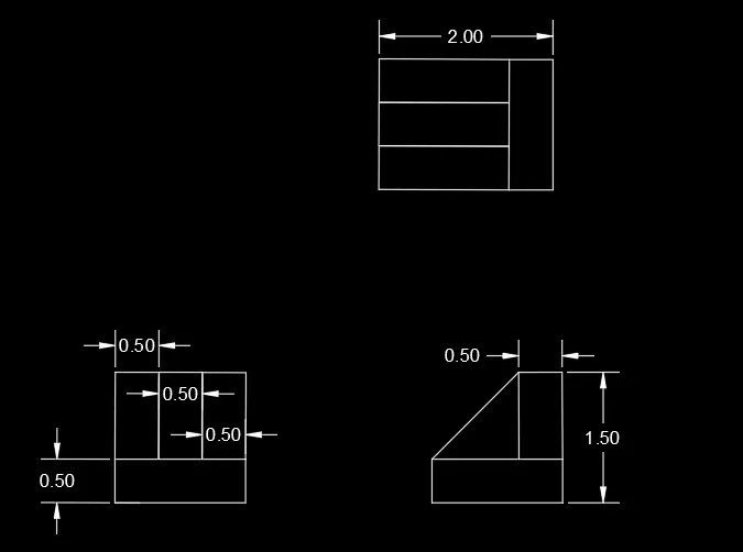
Results - Given sketches are drawn by using decimal units .
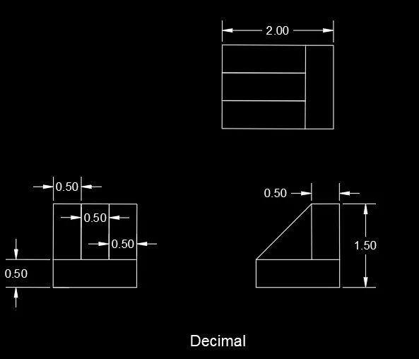
7) Aim - Draw the given sketch by using Decimal units
Introduction - The following commands are used -
i) Line
ii) Rotate
iii) Rectangle
iv) Copy
v) Arc
vi) Fillet
Procedure -
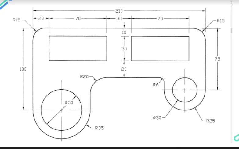
Step by Step procedure of given sketch.
Step 1)
i) Open the New drawing sheet (Cntrl + N)
ii) Change the units - Decimals
iii) Precision - 0.00 and meter
iv) Give the command Rectangle ( Rec)
v) Enter the length = 210
vi) Enter the width = 100
vii) Command Fillet ( F) and select upper corner of rectangle A and B
viii) Enter the radius 15 .
ix) Command Offset (O) take the offset of A and B line of distance 10 in -ve y direction and line AD by 20
in -ve X direction
x) Draw a rectangle by command Rec
xi) Enter length and width = 70 and 30 respectively.
xii) Copy that rectangle at a distance of 30 units

Step 2)
i) Command Lengthen - Delta and enter new dimension -25 for line BC
ii) Command LN and draw a horizontal line from 75 units
iii) Command arc and select Start end and radius from C point .
iv) Similaly from A point draw arc by selecting start end radius .
v) From the center of arc draw Circle of diameter 50 units and 30 units
vii) Use the fillet and enter radius 6 and 20 to join the horizontal line drawn from 75
viii) Trim the unwanted lines .
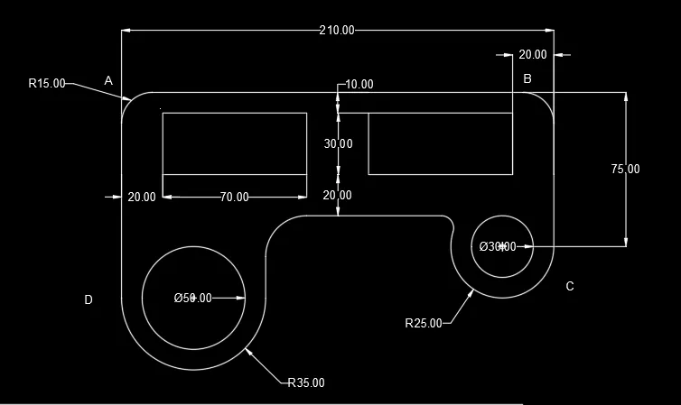
Result - Given geometry is drawn by using Decimal units
8) Aim - Draw the given sketch by using Decimal units
Introduction - The following commands are used -
i) Line
ii) Circle
iii) Fillet
iv) Trim
Procedure -
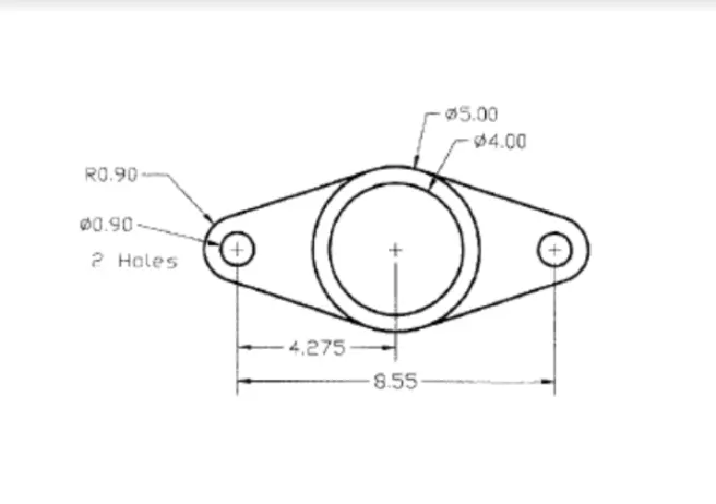
Step by Step procedure of given sketch.
Step 1)
i) Open the New drawing sheet (Cntrl + N)
ii) Change the units - Decimals
iii) Precision - 0.00 and meter
iv) Specify base point for eg (2,2)
v) Command LN and draw a horizontal ( @8.55 , 0)
vi) Command Circle (C) and take the mid point and draw a circle of diameter of 4 and diamter of 5
vii) Take the reference point A and B
viii) Draw the Circle by giving command (C) of diameter 0.90
ix) Copy this circle to point B .
x) Take the same center and draw the Arc by selecting start end radius and entdr radius 0.90
xi) Same procedure at reference point B.
xii) Join theses arc by drawing tangent ,
xiii) Trim the unwanted lines .
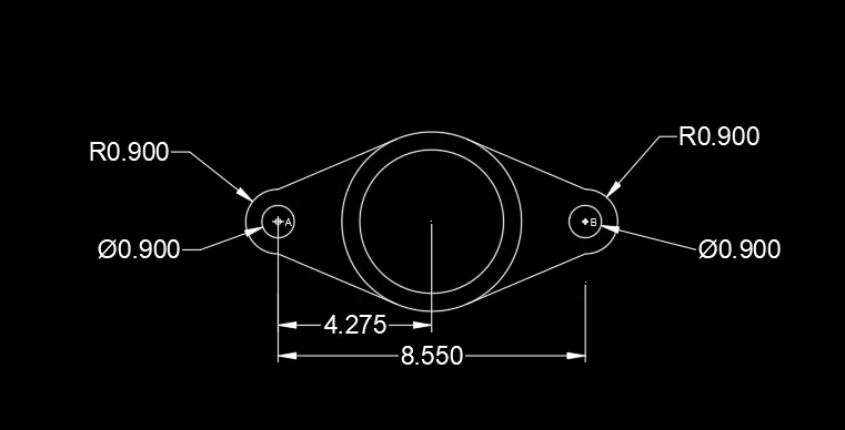
Results - Given sketche is drawn by using Decimal units
9) Aim - Draw the given sketch by using Decimal units
Introduction - The following commands are used -
i) Line
ii) Circle
iii) Fillet
iv) Trim
Procedure -
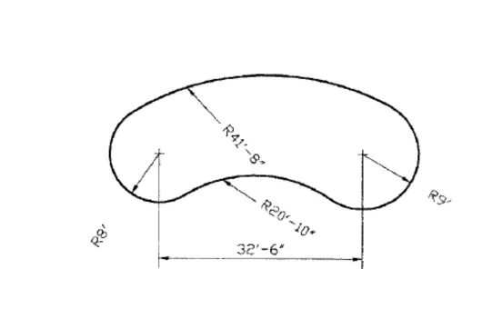
Step by step procedure to draw above geometry -
Step 1)
i) Open the New drawing sheet (Cntrl + N)
ii) Change the units - Architectural
iii) Precision - 0.00 and inches
iv) Specify base point for eg (2,2)
v) Give command Circle (C) and draw the circle of radius 8'
vi) Give the command LN and draw a line of (@32'-61",0) from the center of circle
vii) Give command Circle (C) and draw the circle of radius 9'
viii) Command arc - select start end radius and drae arc of 41'-8" on top and 20'-10" on bottom side
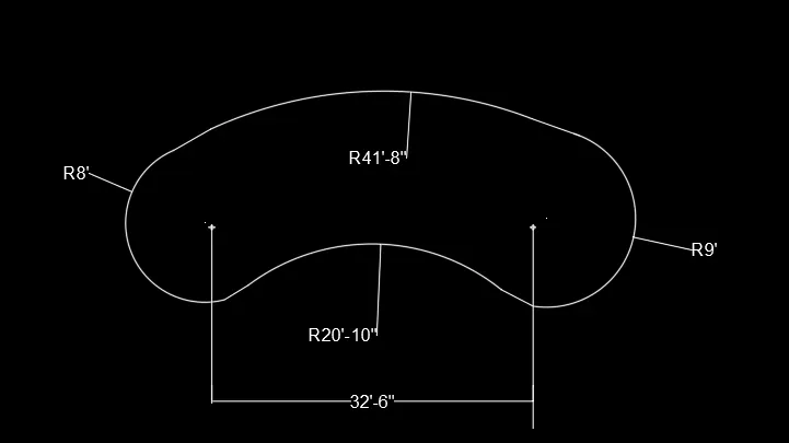
Results - Given sketch is drawn by using Architectural units
10) Aim - Draw the given sketch by using Decimal units
Introduction - The following commands are used -
i) Line
ii) Rectangle
iii) Trim
Procedure -
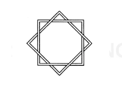
Step by step procedure to draw above geometry -
Step 1)
i) Open the New drawing sheet (Cntrl + N)
ii) Change the units - Decimals
iii) Precision - 0.00 and meter
iv) Command Rectangle (REC)
v) Enter the length = 5
vi) Enter the width = 5
vii) Command offset (O) . give the offset of 0.2 and take the offset of rectangle
viii) Rotate the rectangle at 45 . by using command rotate .(RO)
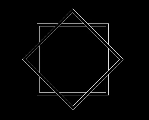
Results - Given sketch are drawn using Decimal units .
11) Aim - Draw the given sketch by using Decimal units
Introduction - The following commands are used -
i) Line
ii) Rectangle
iii) Trim
iv) Copy
Procedure -
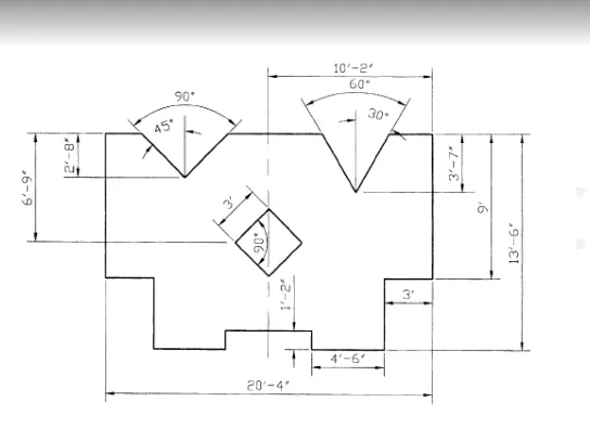
Step by step procedure to draw above geometry -
Step 1)
i) Open the New drawing sheet (Cntrl + N)
ii) Change the units - Architectural
iii) Precision - 0.00 and inches
iv) Command Rectangle (REC)
v) Enter the length = 20'-4"
vi) Enter the width = 13'-6"
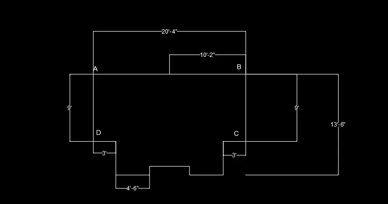
vii) Name as A B C D
viii) Take the midpoint and draw a vertical line at 10'-2"
ix) Take the reference point A and specify point (@0 , -9')
x) copy the same procedure at point B
xi) Specify next point (@3',0)
xii) Specify next point (@0, -4'-6")
xiii) Specify next point (@4'-6",0)
xiv) Specify next point (@0,1'-2")
xv) Specify next point (@4'-6",0)
xvi) Specify next point (@0, - 1'-2")
xvii) Specify next point (@4'-6",0)
xviii) Specify next point (@0, 4'-6")
xix) Specify next point (@3',0)
xx) Specify next point (@0, 9')
xxi) Trim the remaining lines of rectangle
Step 2)
i) Take the center point of (10'-2") and draw a vertical line (@0, -2'-8")
ii) Similarly to the other sides at ( @0 , -3'-7")
iii) Mark the point E F
iv) Draw the line at 45 on right hand side and left hand side of point E
v) Similarly at point F , Draw a line at 30 degress on both side .
vi) Take the Center of (20'-4") . Mark as G
vii) From G , draw a line (@0 , -6'-9")
viii) Mark as H.
ix) Take H as a center and draw a square of side 3" and rotate it at 45 degress.
x) Trim the unwanted lines .
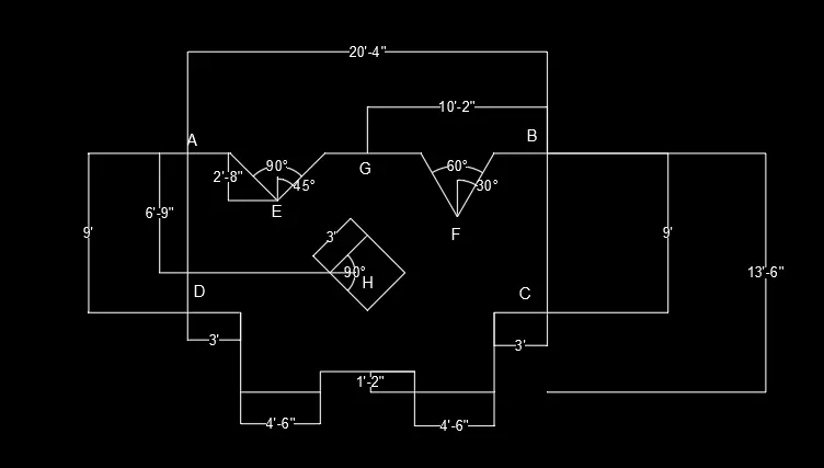
Result - Given sketch is drawn by using Architectural units .