To calculate dead and live load for industrial steel structures and to apply them using TSD
Questions:-
- Calculate dead load in design report based on IS code and apply dead load on the model
- Finishes of 50mm
- Slab as per design
- Brickwall 150mm thickness
- Roofing load based on purlin size
- Ceiling loading 0f 0.3KN per sq m
- Calculate live load in design report based on IS code and apply live load on the model
- Assume the loading based on IS 875
- Roof loading
- Consider equipment loading as 5KN per sq m
- Generate a calculation for 5T crane loading based on following inputs
- Centre to Centre of wheel = 10m
- Weight of crab = 40 KN
- Number of wheels = 4
- Wheel base = 2m
Ans=
AIM:- To explain the answer for each and every question from 1 to 3.
INTRODUCTION:- In this section of question from 1 to 3, I used Tekla structural designer software to answer these question. Besides this, I have used some reference from recorded video session of skill-lync.
PROCEDURE:- Here first I will mention question one by one then answer then in the same manner.
Question- 1. Calculate dead load in design report based on IS code and apply dead load on the model
- Finishes of 50mm
- Slab as per design
- Brickwall 150mm thickness
- Roofing load based on purlin size
- Ceiling loading 0f 0.3KN per sq m
Ans=
Procedure:-
Step-1
DEAD LOADS
i) Initially based on IS 875 part I, all the dead loads in the steel structure were calculated as follows
Unit weight of concrete (Plain cement concrete) = 24 KN/m3
Finish loading = 0.05 X 24 =1.2 KN
Brick wall loading of 1150mm, unit weight = 20 KN/m3
Brick wall loading (GF-1F) = 0.15 X 20 X 5.7 = 17.1 KN/m
Brick wall loading (1F-R) = 0.15 X 20 X 6.8 = 20.4 KN/m
Self-weight of the slab is calculated by software itself
Roof loading based on purlin size = 1.5 KN/m2
Ceiling loading = 0.3 KN/m2
Step-2
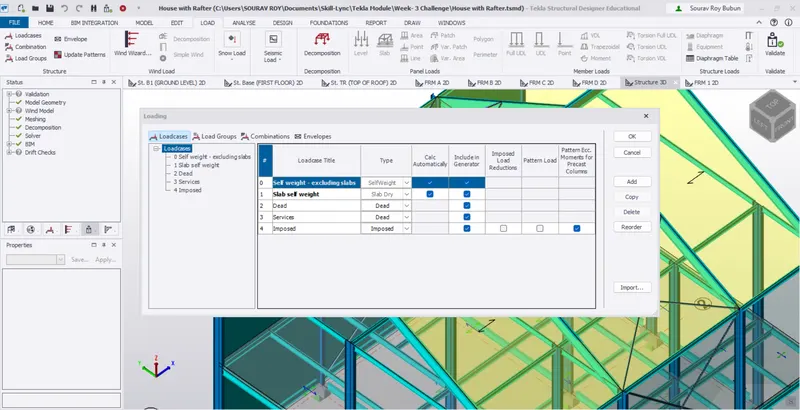
The Load tab click on load cases option at the top left corner to open the loading dialogue box.
Step-3
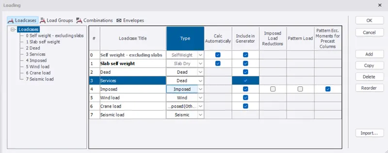
Now add new loadings like wind load , crane load and seismic loads click on Okay.
Step-4
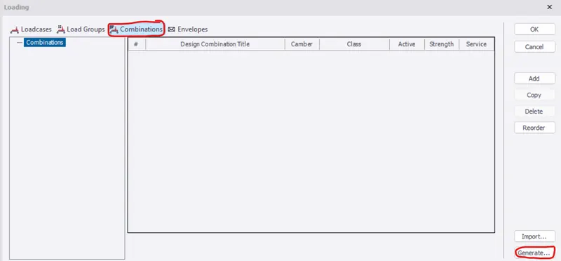
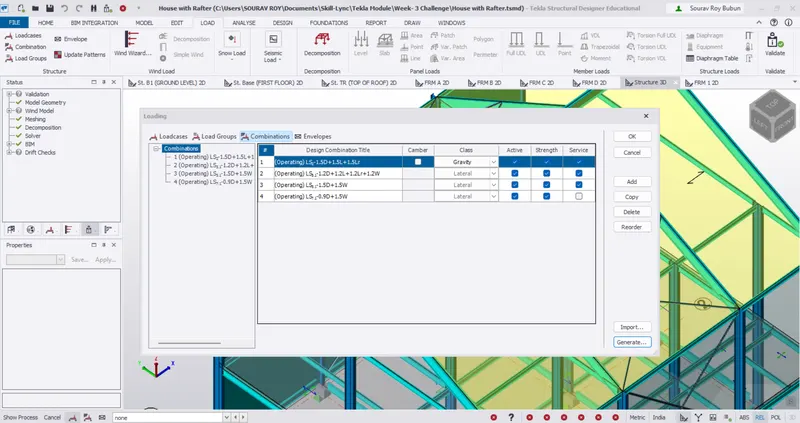
Now in loading tab click on combinations tab and to generate load combinations click on generate option below.
Step-5
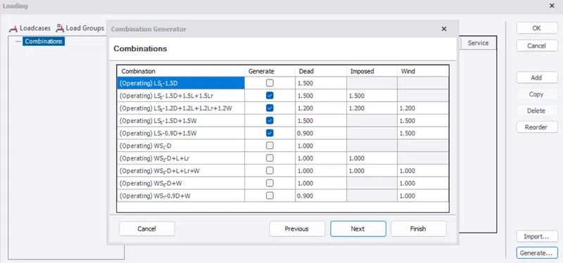
The load combinations will be generated as shown and we can further add and delete combinations as required.
Step-6
Application of Dead load
Select the dead loads option from the drop-down list as shown.
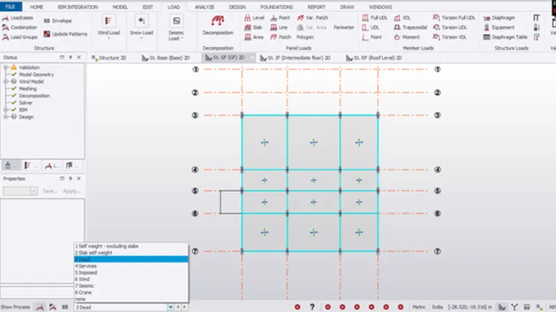
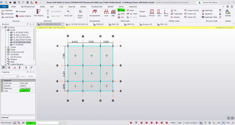
Open a ground floor plan
In the Loading list, select an a Dead Load
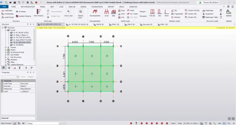
On the Load tab, click Area Load.
In the Properties window insert the value as 1.2 Kn/m^2
Step-7
Now Intermediate floor/ First floor - similarly follw the same procedure ( Except the Staircase area)
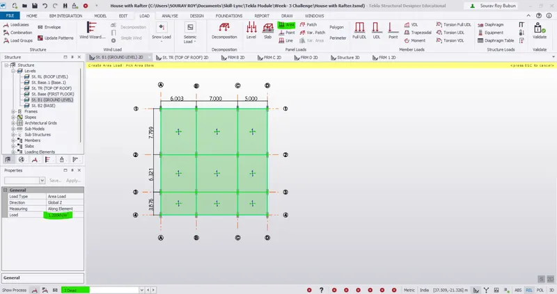
Step-8
Now Validate the model to check any error
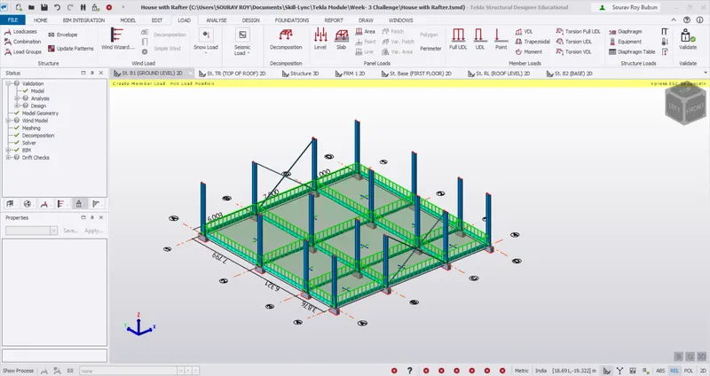
3D view of Dead load
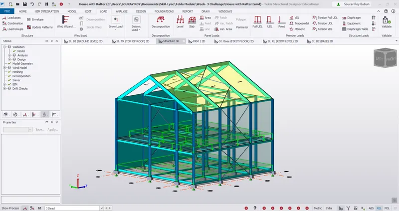
Step-10
Application of Brick wall load
Open a ground floor level within which you want to apply thebrick wall load
In the Loading list, select an Dead load case
On the Load tab, click Full UDL. ( Brick wall comes under UDL loading)
In the Properties window,insert the load value 17.1 kN/m upto 1st floor
Click the beams to which we want to apply the load.
Now for the partition brick wall , Line Load option there
Open a ground floor level
In the Loading list, select Dead load
On the Load tab, click Line load option.
In the Properties window,insert the load value as 17.1 kN/m
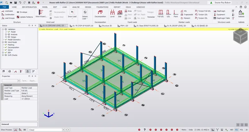
3D view of the Ground floor
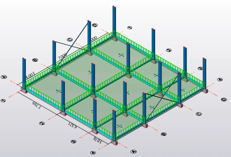
Step-11
Follow the same procedure for first to Roof level.
Insert the load value as 20.4 Kn/m
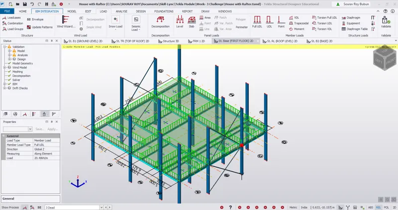
3D view of the first floor
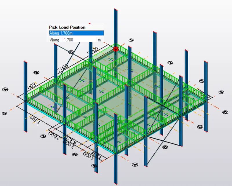
Step-12
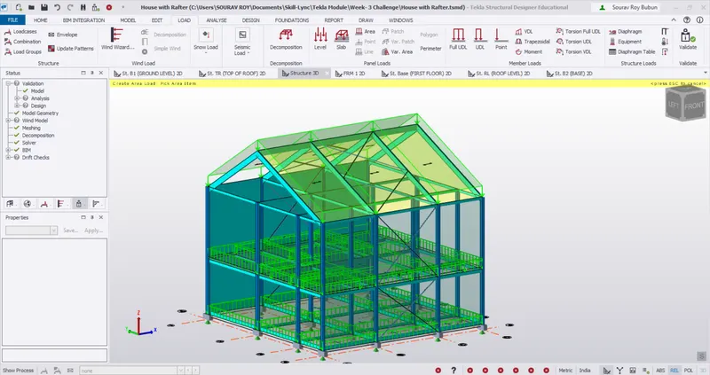
Next the roof load was applied
On the Load tab, click Area Load.
In the Properties window, adjust the load details according to your needs 1.5 kN/m^2
Click the roof panel
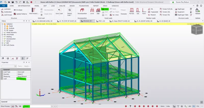
Check the model to see if any error
Result-
Dead load is calculated and applied on model successfully
Question- 2. Calculate live load in design report based on IS code and apply live load on the model
- Assume the loading based on IS 875
- Roof loading
- Consider equipment loading as 5KN per sq m
Ans=
Procedure:-
Step-1
Live load as per IS 875 part 2
Stair case = 5 KN/m2
Workshop (Considering Light Machinery) = 5 KN/m2
Corridor = 5 KN/m2
Meeting Room = 5 KN/m2
Store Room = 5 KN/m2
Toilet = 5 KN/m2
Canteen = 3 KN/m2
Office = 3 KN/m2
Conference = 5 KN/m2
Equipment = 10 KN/m2
Administration Room = 5 KN/m2
Roof load for on accessible = 0.75 KN/m2
Step-2
In the drop-down list select imposed as load case
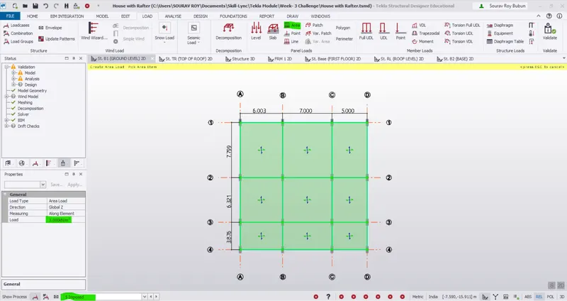
Open a ground floor level
In the Loading tab, select an Imposed loa case
On the Load tab, click on Area Load.
In the Properties window, insert the loading value according to functionality of rooms
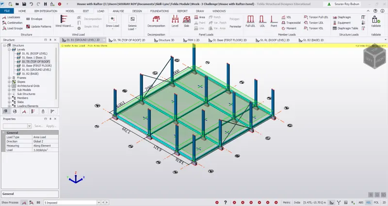
Click on Front view to see the loading intensity difference
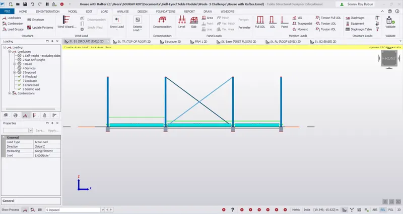
Check the model
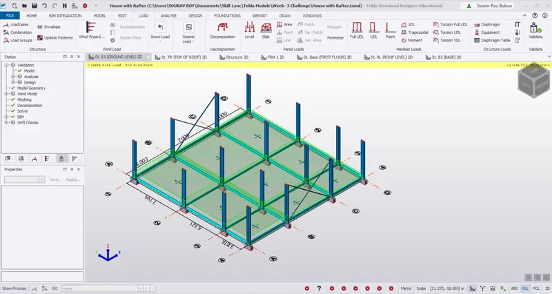
Step-3
Follow the same procedure for first floor and Roof level also
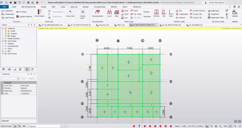
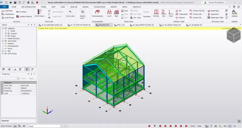
3D view
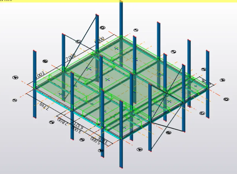
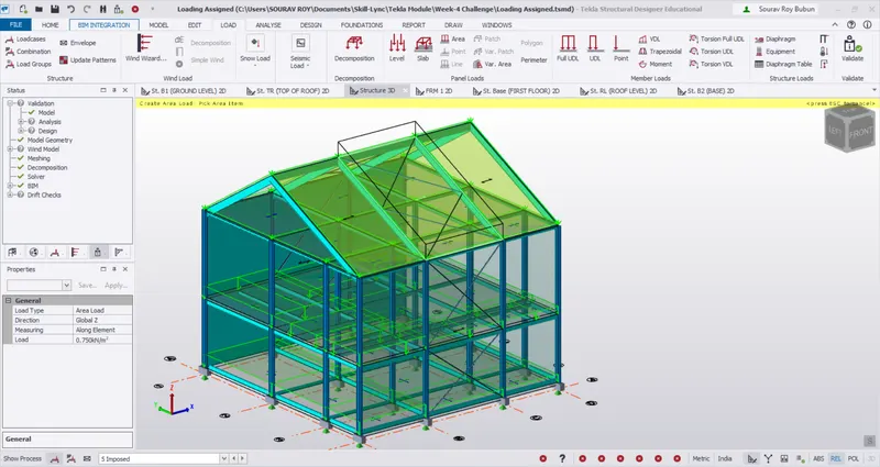
Similarly live loads, the loads were applied on roof level.
As the roof level doesn’t carry much load only 0.75kN/m^2 is applied for all rooms.
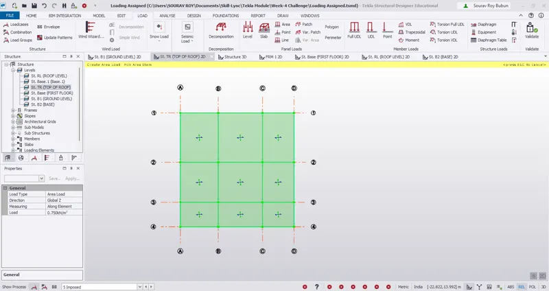
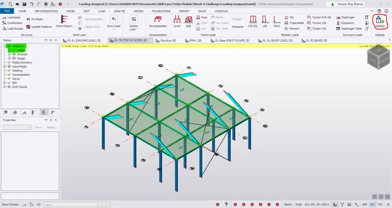
Validate the model to check for any errors
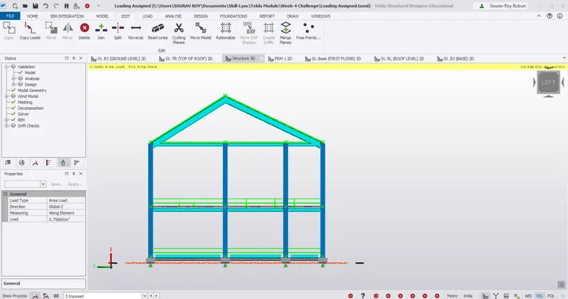
Now we have to apply live loads of the roof. As the slope of roof is greater than 10 degree a load of 0.750kN/m^2 was applied.
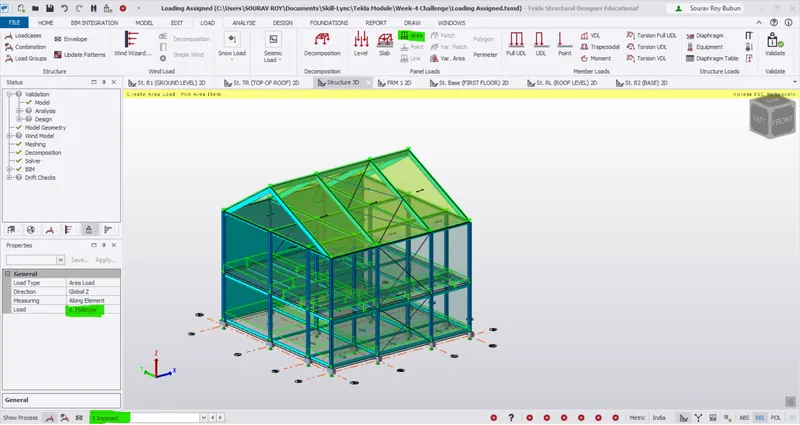
Result-
Live load is calculated as per IS 875 part 2 and applied on model successfully
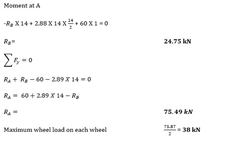
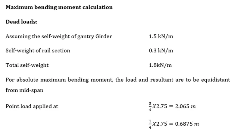
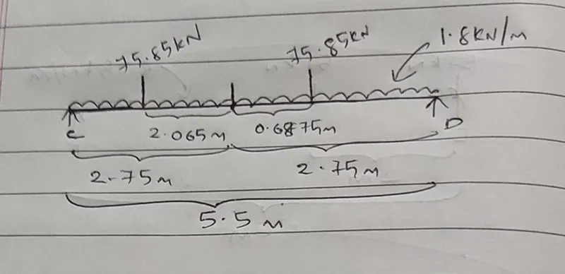
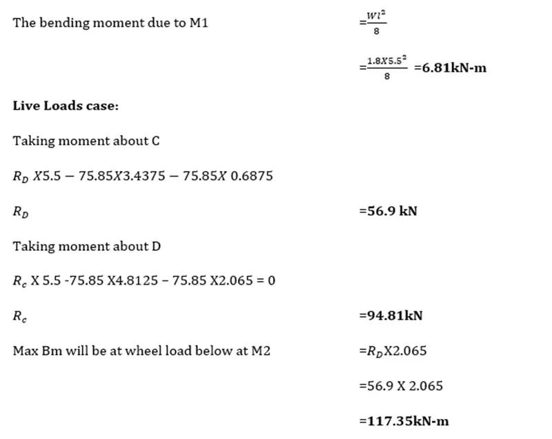
Question- 3. Generate a calculation for 5T crane loading based on following inputs
- Centre to Centre of wheel = 10m
- Weight of crab = 40 KN
- Number of wheels = 4
- Wheel base = 2m
Ans=
Procedure:-
Step-1
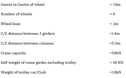
Data
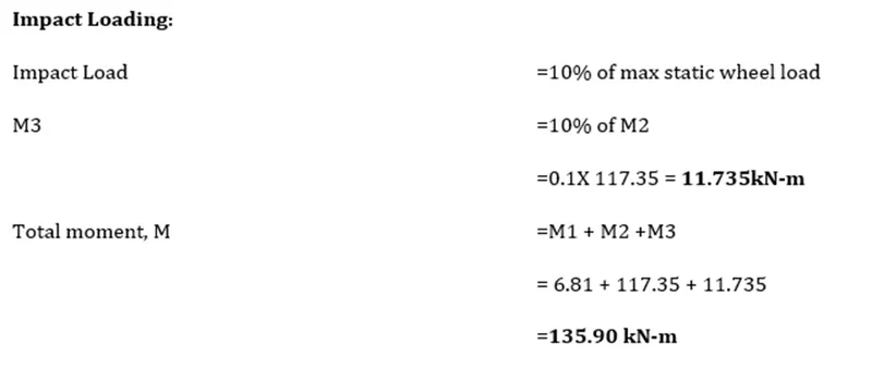
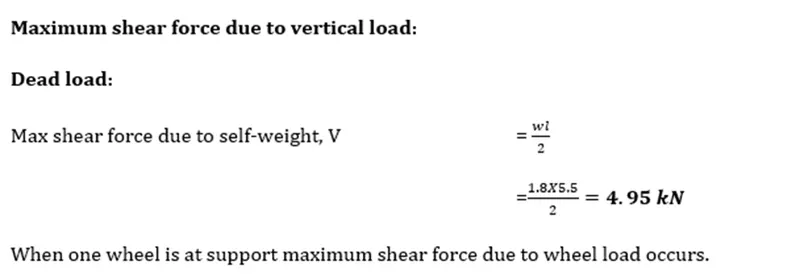
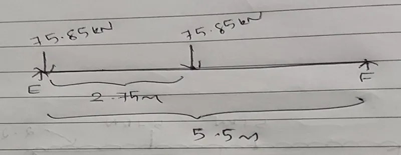
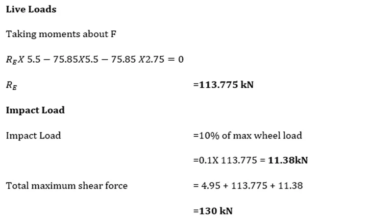
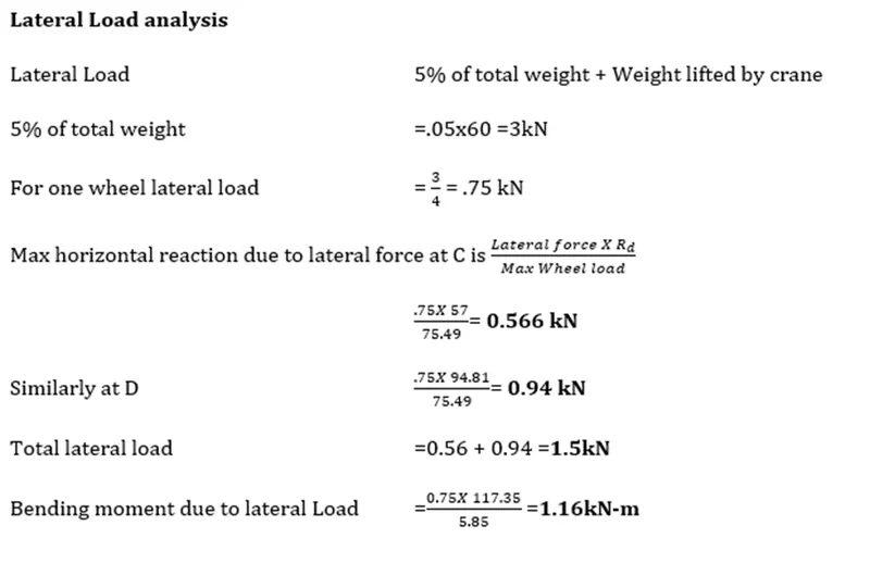
Result -
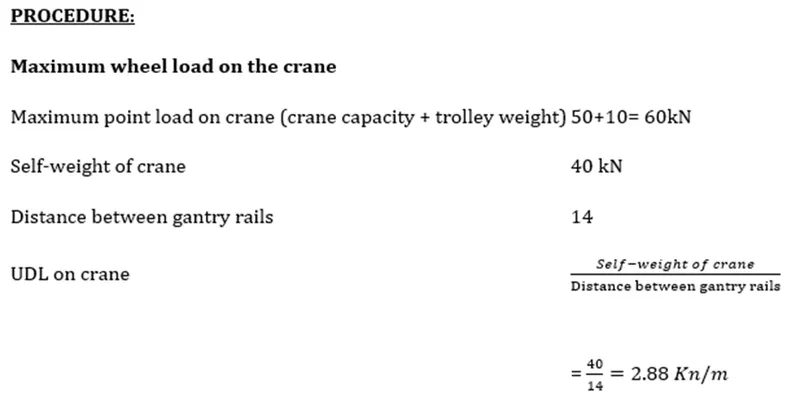
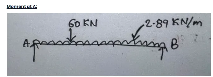
A 5T crane loadings is manually calculated.
Final Result:-
All the qusestions from 1 to 3 are answered with detailed elaboration.
Conclusion:-
All the results has been displayed and Tekla file regarding dead and live load assignment is attached in this project.