Creating a Floor plan, Footing detail and Isometric view using AutoCad
PROJECT:- DRAW THE SKETCH ACCORDING TO C1 FILE
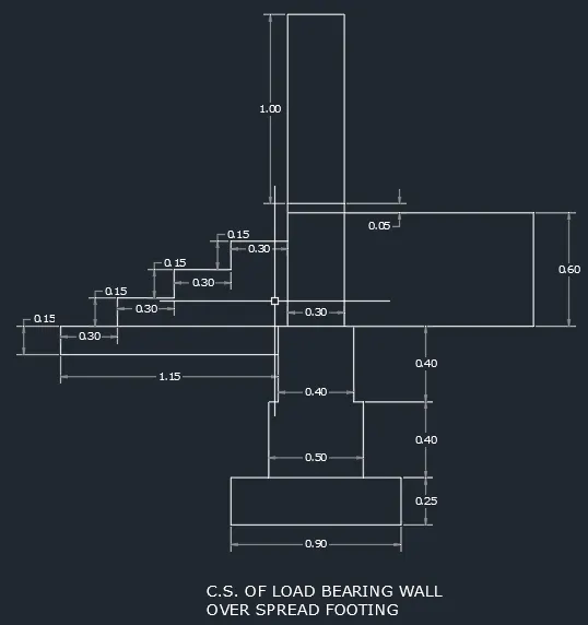
AIM:- To draw a cross section of load bearing wall over spread footing and provide step by step process for drawing this structure.
INTRODUCTION:-
To draw this cross section of load bearing wall over spread footing, I have used several autocad commands like- line,trim, rectangle etc.Moreover, I used both rectangular coordinate system and polar coordinate system to draw various steps in this drawing. Also, I used dimesion command for measuing the dimensions in Autocad along with text command to write drawing name.
PROCEDURE:-
- Provide a command "rectangle" and provide a coorinate (2,1) then enter.
- Provide the dimension of rectangle (@0.90,0.25)
- Press a command "Line" and specify the first point of the top corner of that rectangle and specify the next point as (@0.2,0) and then press enter.
- Type a command "rectangle" and specify the first point as the inner end of that line (0.2).
- provide the dimension of rectangle (@0.5,0.4) and enter.
- press command "trim" then enter, and then right click on mouse and tream middle portion of the top side of rectangle and press escape.
- Press a command "Line" and specify the first point of the top corner of that rectangle and specify the next point as (@0.05,0) and then press enter.
- Type a command "rectangle" and specify the first point as the inner end of that line (0.05).
- provide the dimension of rectangle (@0.4,0.4) and enter.
- press command "trim" then enter, and then right click on mouse and tream middle portion of the top side of rectangle and press escape.
- Press a command "Line" and specify the first point of the top corner of that rectangle and specify the next point as (@0.05,0) and then press enter.
- Type a command "rectangle" and specify the first point as the inner end of that line (0.05).
- provide the dimension of rectangle (@0.3,0.6) and enter.
- Type a command "rectangle" and specify the first point as the top end of that previous rectangle.
- Provide the dimensions of rectangle as (@0.3,0.05) and enter.
- Type a command "rectangle" and specify the first point as the top end of that previous rectangle.
- Provide the dimensions of rectangle as (@0.3,1) and enter.
- Type a command "rectangle" and move the cursor to the left side top corner of third rectangle from bottom an then specify the first coordinate point.
- Provide a dimension of that rectangle as (@-1.15,-0.15) and enter.
- Type the command line and specify the first point as top left corner of that previous rectangle.
- Then type (@0.3<0) and enter.
- Type (@0.15<90) and enter.
- Type (@0.3<0) and enter.
- Type (@0.15<90) and enter.
- Type (@0.3<0) and enter.
- Type (@0.15<90) and enter.
- Type (@0.3<0) and enter.
- Type the command Dimension and then provide dimensions according to sketch.
- Type text command to write details of drawing and write it accordingly.
RESULT:-
FINAL SKETCH OF CROSS SECTION OF LOAD BEARING WALL OVER SPREAD FOOTING.
PROJECT:- DRAW THE SKETCH ACCORDING TO C2 FILE
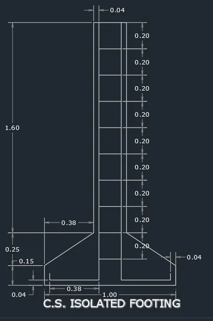
AIM:- To draw a cross section of isolated footing and provide step by step process for drawing this structure.
INTRODUCTION:-
To draw this cross section of isolated footing, I have used several autocad commands like- line,offset,copy, trim, rectangle etc. Moreover, I used rectangular coordinate system to draw various steps in this drawing. Also, I used dimesion command for measuing the dimensions in Autocad along with text command to write drawing name.
PROCEDURE:-
STEP-1
- Provide a command "line" and provide a coorinate (2,1) then enter.
- Enter the next cordinate as (@0,0.15)
- Enter the next cordinate as (@0.38,0.25)
- Enter the next cordinate as (@0,1.6)
- Enter the next cordinate as (@0.24,0)
- Enter the next cordinate as (@0,-1.6)
- Enter the next cordinate as (@0.38,-0.25)
- Enter the next cordinate as (@0,-0.15)
- Enter the command "close".
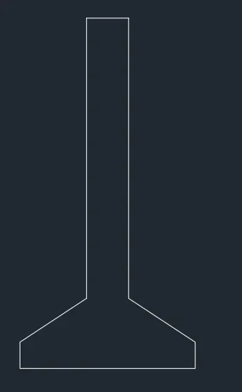
STEP-2
- Draw line at a distance of 0.04 units from the top left corner of "I"
- With dynamic input on give value 0.04, then give the length of the 1st line 1.96
- Next give the coordinate @-0.38,0
- Draw the the third line bend by giving the coordinates @0,0.06
STEP-3
- Draw line at a distance of 0.04 units from the top right corner of "I"
- With dynamic input on give value 0.04, then give the length of the 1st line 1.96
- Next give the coordinate @-0.38,0
- Draw the the third line bend by giving the coordinates @0,0.06
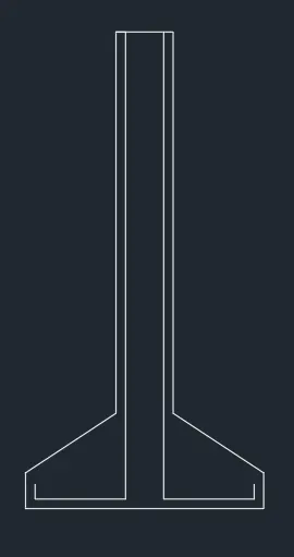
STEP-4
- Give offset from the top line with an offset distance of 0.2 units.
- Give the command "o" and select the object. then give the offset distance as 0.2 and select multiple option on 9 such lines
- Trim the excess lines.
- Type the command Dimension and then provide dimensions according to sketch.
- Type text command to write details of drawing and write it accordingly.
RESULT:-
FINAL SKETCH OF ISOLATED FOOTING.
PROJECT:- DRAW THE SKETCH ACCORDING TO C3 FILE
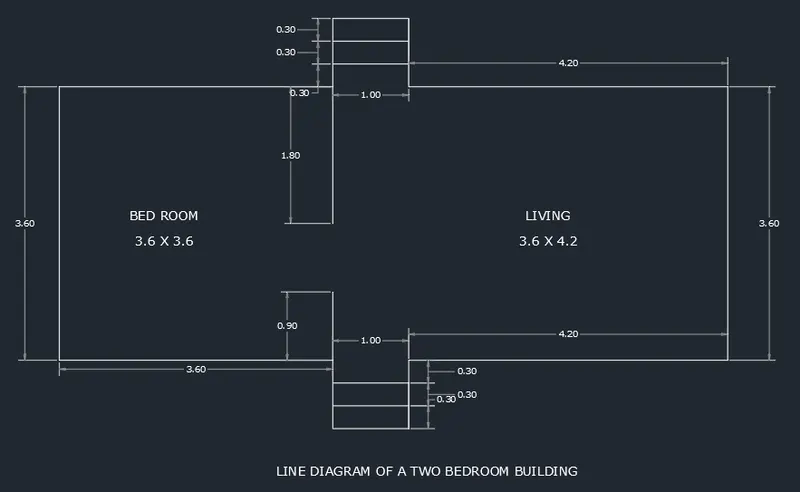
AIM:- To draw a line diagram of a two bedroom building.
INTRODUCTION:-
To draw this line diagram of a two bedroom, I have used several autocad commands like- line,offset etc. Moreover, I used rectangular coordinate system to draw various steps in this drawing. Also, I used dimesion command for measuing the dimensions in Autocad.
PROCEDURE:-
- Type a command "line" and enter, and provide a coorinate (2,1) then enter.
- Type a command "Line" and give coordinate (@3.6,0) and press enter.
- Provide a coordinate (@0,0.9) and enter.
- Provide a coordinate (@0,-1.8) and enter.
- Provide a coordinate (@1,0) and enter.
- Provide a coordinate (@0,0.9) and enter.
- Provide a coordinate (@4.2,0) and enter.
- Provide a coordinate (@0,3.6) and enter.
- Provide a coordinate (@-4.2,0) and enter.
- Provide a coordinate (@0,0.9) and enter.
- Provide a coordinate (@-1,0) and enter.
- Provide a coordinate (@0,-2.7) and enter.
- Provide a coordinate (@0,1.8) and enter.
- Provide a coordinate (@-3.6,0) and enter.
- Provide a coordinate (@0,-3.6) and enter.
- press escape key.
- Type a command "Offset" and press enter.
- Then set an offset distance 0.3 and provide offset of stair steps by selecting multiple option 2 such line on bottom side.
- Again set an offset distance 0.3 and provide offset of stair steps by selecting multiple option 2 such line on bottom side.
- Type the command Dimension and then provide dimensions according to sketch.
- Type text command to write details of drawing and write it accordingly.
RESULT:-
FINAL SKETCH A TWO BEDROOM BUILDING.
PROJECT:- DRAW THE SKETCH ACCORDING TO C4 FILE
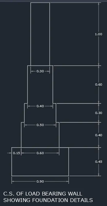
AIM:- To draw a cross section of load bearing wall showing foundation details.
INTRODUCTION:-
To draw this cross section of load bearing wall showing foundation details, I have used several autocad commands like- rectangle,line,offset etc. Moreover, I used rectangular coordinate system to draw various steps in this drawing. Also, I used dimesion command for measuing the dimensions in Autocad along with text command to write drawing name.
PROCEDURE:-
- Provide a command "rectangle" and provide a coorinate (2,1) then enter.
- Provide the dimension of rectangle (@0.90,0.6)
- Press a command "Line" and specify the first point of the top corner of that rectangle and specify the next point as (@0.15,0) and then press enter.
- Type a command "rectangle" and specify the first point as the inner end of that line (0.15).
- provide the dimension of rectangle (@0.6,0.4) and enter.
- press command "trim" then enter, and then right click on mouse and tream middle portion of the top side of rectangle and press escape.
- Press a command "Line" and specify the first point of the top corner of that rectangle and specify the next point as (@0.05,0) and then press enter.
- Type a command "rectangle" and specify the first point as the inner end of that line (0.05).
- provide the dimension of rectangle (@0.5,0.3) and enter.
- press command "trim" then enter, and then right click on mouse and tream middle portion of the top side of rectangle and press escape.
- Press a command "Line" and specify the first point of the top corner of that rectangle and specify the next point as (@0.05,0) and then press enter.
- Type a command "rectangle" and specify the first point as the inner end of that line (0.05).
- provide the dimension of rectangle (@0.4,0.6) and enter.
- press command "trim" then enter, and then right click on mouse and tream middle portion of the top side of rectangle and press escape.
- Press a command "Line" and specify the first point of the top corner of that rectangle and specify the next point as (@0.05,0) and then press enter.
- Type a command "rectangle" and specify the first point as the inner end of that line (0.05).
- provide the dimension of rectangle (@0.3,1) and enter.
- press command "trim" then enter, and then right click on mouse and tream middle portion of the top side of rectangle and press escape.
- Type the command Dimension and then provide dimensions according to sketch.
- Type text command to write details of drawing and write it accordingly.
RESULT:-
FINAL SKETCH OF A CROSS SECTION OF A LOAD BEARING WALL.
PROJECT:- DRAW THE SKETCH ACCORDING TO C5 FILE
AIM:- To draw a isometric view of step.
INTRODUCTION:-
To draw this isometric view of step, I have used several autocad commands like- line,copy etc. Moreover, I used isometric view system to draw various steps in this drawing. Also, I used dimension command for measuing the dimensions in Autocad along with text command for writing details of drawing.
PROCEDURE:-
- To work with isometric view -Command "ds" and select snap and grid tab and turn snap off & grid off, then click ok.
- Make sure that ortho mode is on.
Step-1
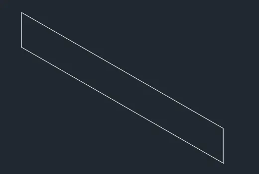
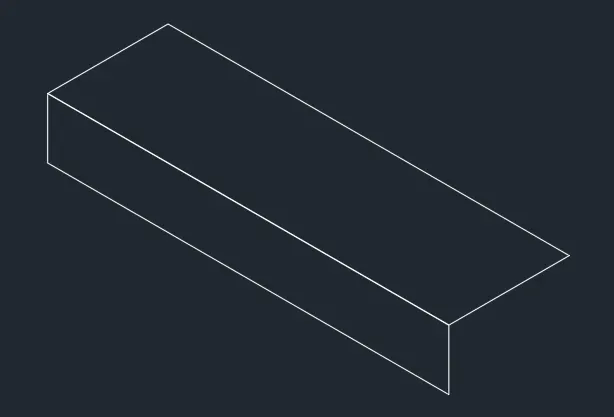
- From isometric drafting select isoplane left.
- Give command "L" and moving the cursor (by pressing f5 key) to -x direction(left) give 1 unit and press enter.
- Moving the cursor (by pressing f5 key) to +y direction(top), give 0.15 unit and press enter.
- Moving the cursor to +x direction and give 1 unit and moving the cursor to -y direction(downwards) give 0.15 unit and press enter.
Step-2
- Change the isometric drafting to isoplane top (by pressing f5 key).
- Move the cursor to back and give 0.3 unit from the top left corner and then press enter.
- Move the cursor to right direction (by pressing f5 key) and give 1 unit and press enter.
- Move the cursor to the front and give 0.3 unit and press enter.
Step-3
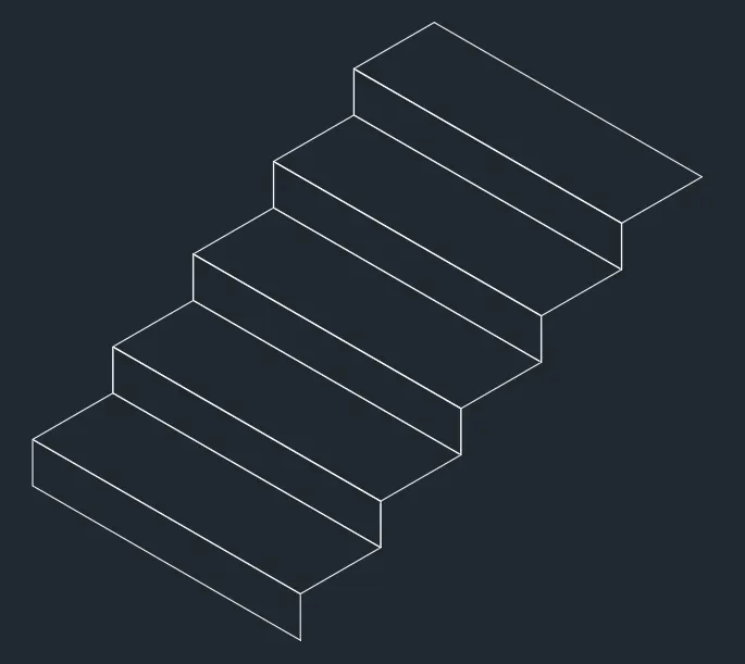
- Change the isometric drafting to isoplane right (by pressing f5 key).
- Copy the object drawn, ortho off.
- Command "co" and specify the base point and place it to new point.
- Repeat it until 4 steps are formed.
Step-4
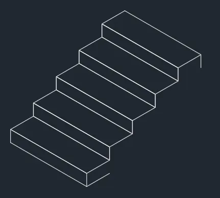
- Copy the horizontal distance of 0.3 downwards on the starting end of step with isoplane right.
- Also copy the vertical distance of 0.15 on the last end step.
Step-5
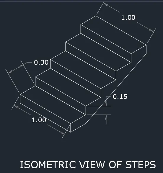
- With isoplane right join the two ends with ortho off.
- Type Line command "L", and then select first point as the bottom point drawn in step 4, and then the second point as end point of vertical line drawn in step 4.
- Type the command Dimension and then provide dimensions according to sketch.
- Type text command to write details of drawing and write it accordingly.
RESULT:-
FINAL SKETCH OF A ISOMETRIC VIEW OF STEP.
PROJECT:- DRAW THE SKETCH ACCORDING TO C6 FILE
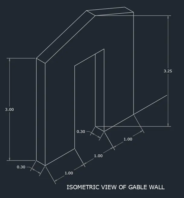
AIM:- To draw a isometric view of gable wall.
INTRODUCTION:-
To draw this isometric view of step, I have used several autocad commands like- line,copy etc. Moreover, I used isometric view system to draw various steps in this drawing. Also, I have used dimension command for measuing the dimensions in Autocad along with text command for writing details of drawing.
PROCEDURE:-
- To work with isometric view -Command "ds" and select snap and grid tab and turn snap off & grid off, then click ok.
- Make sure that ortho mode is on.
Step-1
- From isometric drafting select isoplane right.
- Give command "L" and moving the cursor to left give 1 unit and press enter.
- Pointing the cursor upward give 3 unit and press enter.
- Change the isoplane to right (by pressing f5 key) and give 3 unit and press enter.
- Pointing the cursor downwards and give 3 unit and press enter.
- Again pointing the cursor to left and give 1 unit and press enter.
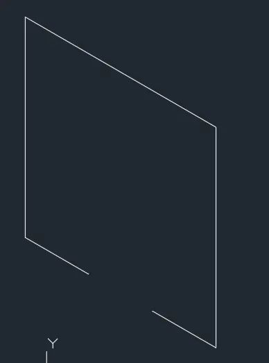
Step-2
- Again take line command and draw line upwards of 2.42 unit from the starting point of step 1.
- Draw 1 unit towards the right and press enter.
- Draw 2.42 unit downwards and press enter.
- Click on the end point of figure in step 1, so that a closed figure is obtained.
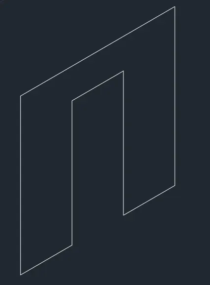
Step-3
- Change to isoplane left and draw 0.3 unit as thickness on the left side of figure.
- Move the cursor upwards and draw 3 units and join.
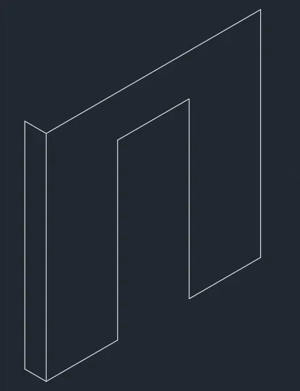
Step-4
- Give the thickness of opening, isoplane left.
- 0.3 unit towards left and 2.12 unit upwards.

Step-5
- Extend the thickness line of opening 1.13 units upwards ie, total 3.25 units from bottom.
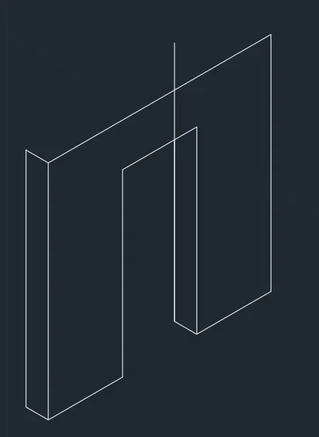
Step-6
- With ortho off, draw a line between the corner of left side and the projected line done in step 5.
- Draw it to the other side also till it meets the right corner.
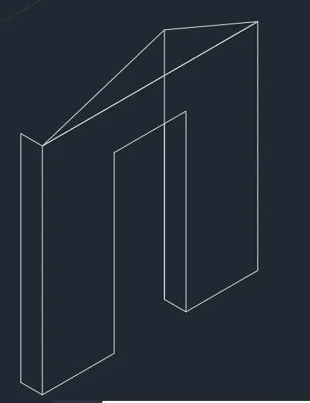
Step-7
- Draw the vertical line with ortho on to join the center portion and erase the projection and horizontal lines.
- Give the thickness of top opening, select isoplane top( by pressing f5 key).
- 0.3 unit towards left back and press escape.
- Change the isoplane view to isoplane left.
- Type line command and click top right side corner and give 0.3 unit towards left back.
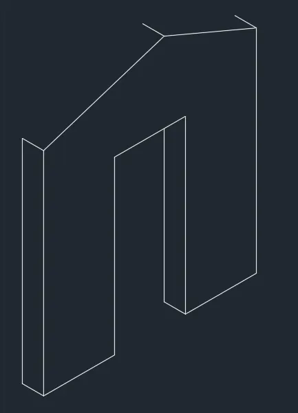
Step-8
- Copy both the inclined lines and join the right end.
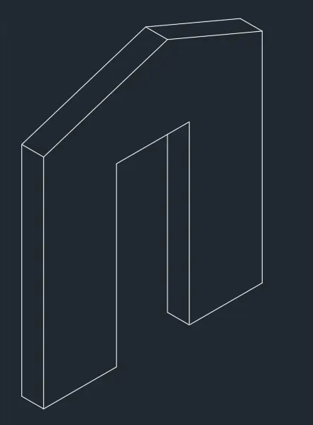
RESULT:-
FINAL SKETCH OF A ISOMETRIC VIEW OF GABLE WALL.