Drafting of various geometries using Chamfer, Fillet tool in AutoCad
AIM:- To draw a geometry (polygonal shape) according to provided drawing.
INTRODUCTION:-
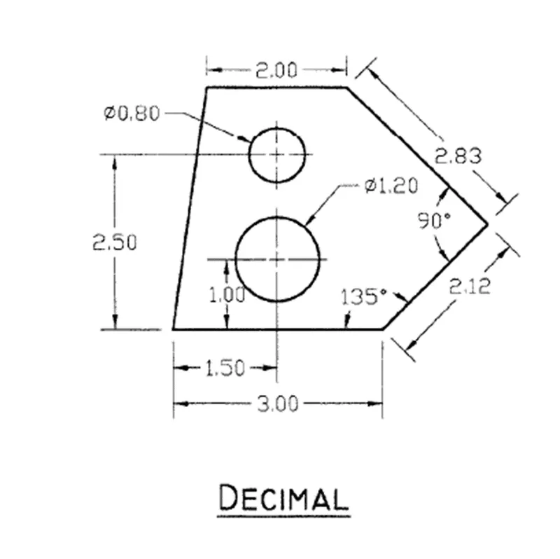
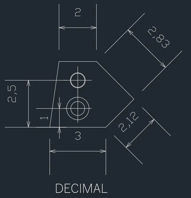
To draw this polygonal shape, I have used several autocad commands like- line,circle, point etc., and I set dimension (Decimal) in Autocad. Moreover, I used both rectangular coordinate system and polar coordinate system to draw various steps in this drawing. Also, I used dimesion command for measuing the dimensions in Autocad along with text command to write drawing name.
PROCEDURE:-
Open Autocad and type a command "Unit" and press enter, then set unit as decimal and set angle in degree- base angle is east -mark angle direction as anticlockwise.
- Type a command "line" and provide a coorinate (2,1) then enter.
- Provide the coordinate of line (@3<0)
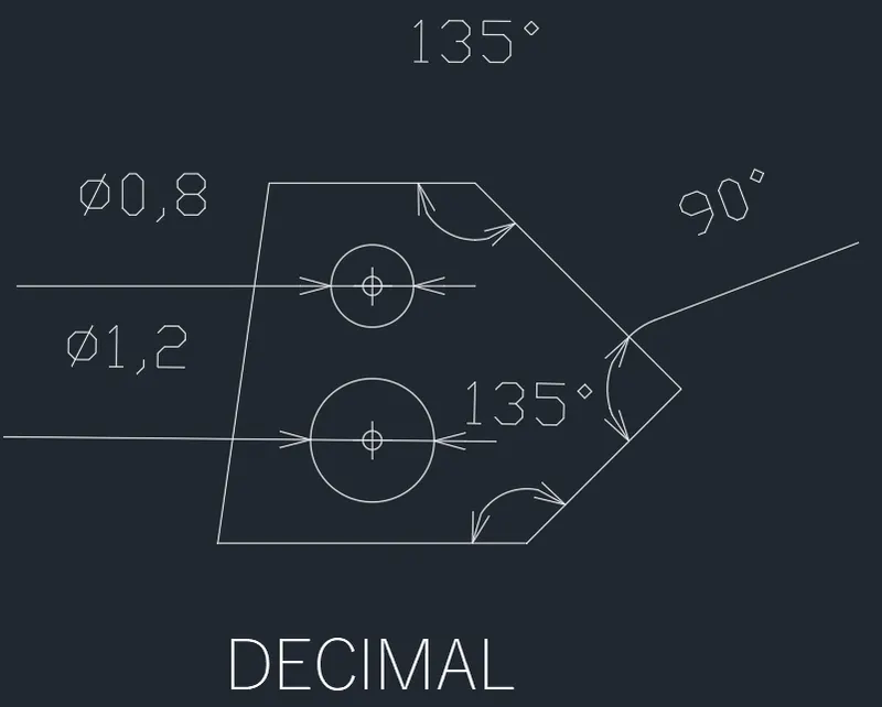
- Provide the next coordinate of line (@2.12<45) (According to Polar coordinate system calculated angle is, 180-135=45)
- Provide the coordinate of line (@2.83<135)(According to Polar coordinate system calculated angle is, 180-(90/2)=135)
- Provide the coordinate of line (@2<180)
- Type a command close and press enter.
- To draw first circle type a command "circle" and provide a coorinate (3.5,2) then enter.
- click dimension and provide dimension as 1.2 and enter.
- To draw second circle type a command "circle" and provide a coorinate (3.5,3.5) then enter.
- click dimension and provide dimension as 0.8 and enter.
RESULT:-
FINAL SKETCH OF A GEOMETRY (POLYGONAL SHAPE).
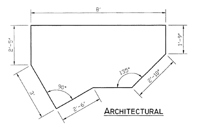
AIM:- To draw a geometry (using architectural units) according to provided drawing.
INTRODUCTION:-
To draw this geometry, I have used only line command, and I set dimension (Architecture) in Autocad. Moreover, I used both rectangular coordinate system and polar coordinate system to draw various steps in this drawing. Also, I used dimesion command for measuing the dimensions in Autocad along with text command to write drawing name.
PROCEDURE:-
Open Autocad and type a command "Unit" and press enter, then set unit as Architectural and set angle in degree- base angle is east -mark angle direction as anticlockwise.
- Keep polar tracking on for 15,30,45,60 and so on.
- Draw a line by providing coordinate (@2'-6"<210)
- With the help of polar tracking set the angle of 90 degree with current line and give it a dimension of 3" and press enter.
- With the help of polar tracking draw a vertical line and give the dimension as 2'-5" and press enter.
- Draw a line by providing coordinate (@8'-0"<0) and press enter.
- Draw another line by providing coordinate (@1'-9"<270) and press enter.
- Draw a line by providing coordinate (@2'-10"<225) and press enter.
- Type a command close and press enter.
RESULT:-
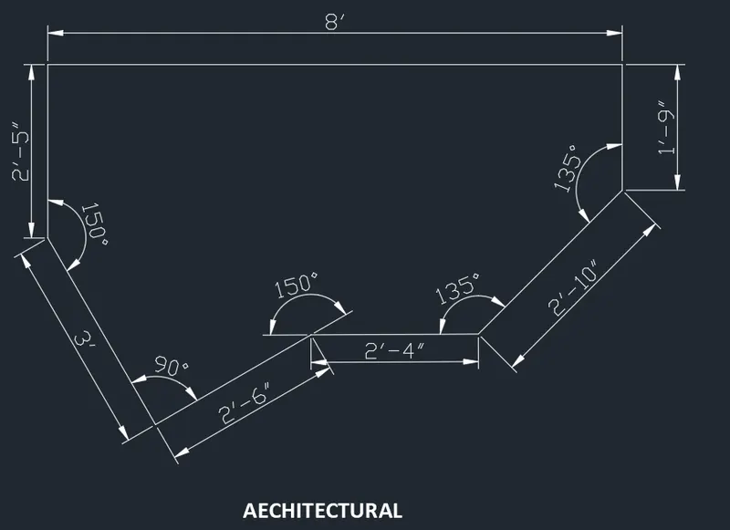
FINAL SKETCH OF A GEOMETRY (ARCHITECTURAL).
AIM:- To draw a geometry (using Engineering units) according to provided drawing.
INTRODUCTION:-
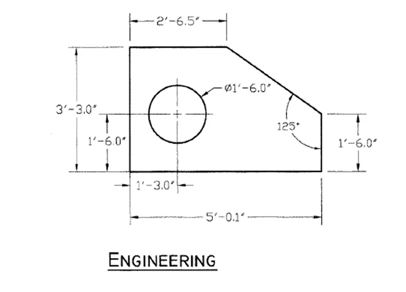
To draw this geometry, I have used several autocad commands like- line,circle, point etc., and I set dimension (Engineering) in Autocad. Moreover, I used both rectangular coordinate system and polar coordinate system to draw various steps in this drawing. Also, I used dimesion command for measuing the dimensions in Autocad along with text command to write drawing name.
PROCEDURE:-
Open Autocad and type a command "Unit" and press enter, then set unit as Engineering and set angle in degree- base angle is east -mark angle direction as anticlockwise. Type a command "DIMSTYLE" and press enter, then click to modify and go to primary unit tab and set it Engineering and set the precision to 0'-0.0" and cick ok.
- Type a command "line" and provide a coorinate (0,0) then enter.
- Draw a line by providing coordinate (@1'-6.0"<270) and press enter.
- Provide another coordinate (@5'-0.1"<180) and press enter.
- Give next coordinate (@3'-3.0"<90) and press enter.
- Provide another coordinate (@2'-6.5"<0) and press enter.
- Type a command close and press enter.
- Type a command "circle" and give a coordinate (1'-3.0",1'-6.0") and press enter.
- Click on diameter and type a diameter of 1'-6.0" and press enter.
RESULT:-
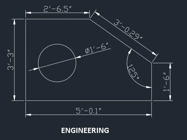
FINAL SKETCH OF A GEOMETRY (ENGINEERING).
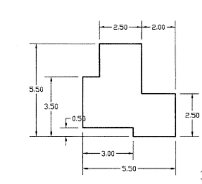
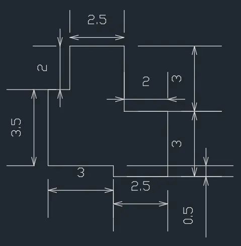
AIM:- To draw a geometry (using decimal units) according to provided drawing.
INTRODUCTION:-
To draw this geometry, I have used 0nly line command, and I set dimension (Decimal) in Autocad. Moreover, I used both rectangular coordinate system and polar coordinate system to draw various steps in this drawing.
PROCEDURE:-
Open Autocad and type a command "Unit" and press enter, then set unit as decimal and set angle in degree- base angle is east -mark angle direction as anticlockwise. Type a command "DIMSTYLE" and press enter, then click to modify and go to primary unit tab and set it decimal and set the precision to 0.00 and cick ok.
- Type a command "line" and provide a coorinate (0,0) then enter.
- Give a coordinate (@2.5<180) and press enter.
- Provide the next coordinate (@0.5<90) and enter.
- Provide the next coordinate (@3<180) and enter.
- Provide the next coordinate (@3.5<90) and enter.
- Provide the next coordinate (@1<0) and enter.
- Provide the next coordinate (@2<90) and enter.
- Provide the next coordinate (@2.5<0) and enter.
- Provide the next coordinate (@3<270) and enter.
- Provide the next coordinate (@2<0) and enter.
- Provide the next coordinate (@2.5<270) and enter or type "close" and enter.
RESULT:-
FINAL SKETCH OF THE GEOMETRY.
AIM:- To draw a geometry (using decimal units) according to provided drawing.
INTRODUCTION:-
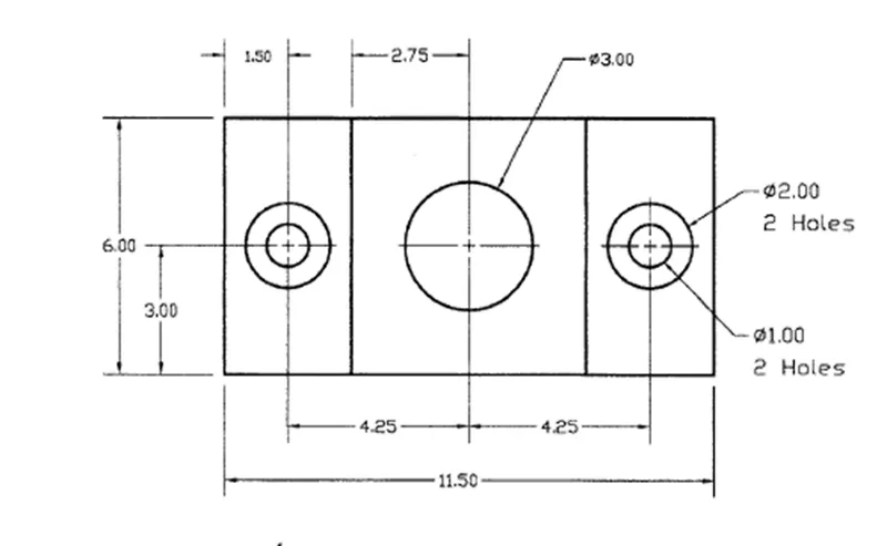
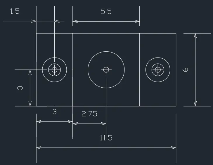
To draw this geometry, I have used several autocad commands like- line,circle, offset, point etc., and I set dimension (Decimal) in Autocad. Moreover, I used both rectangular coordinate system and polar coordinate system to draw various steps in this drawing.
PROCEDURE:-
Open Autocad and type a command "Unit" and press enter, then set unit as decimal and set angle in degree- base angle is east -mark angle direction as anticlockwise. Type a command "DIMSTYLE" and press enter, then click to modify and go to primary unit tab and set it decimal and set the precision to 0.00 and cick ok.
- Type a command "line" and provide a coorinate (0,0) then enter.
- Provide the next coordinate (@11.5<180) and enter.
- Provide the next coordinate (@6<90) and enter.
- Provide the next coordinate (@11.5<0) and enter.
- Type a command close and press enter.
- Type a command "offset" and give offset distance 3 and press enter, then provide offset from left and right.
- Type a command "circle" and provide a coordinate as (-1.5,3) and press enter.
- Click on diameter and type a diameter of 2 and press enter.
- Again type a command "circle" and provide a coordinate as (-1.5,3) and press enter.
- Click on diameter and type a diameter of 1 and press enter.
- Type command "copy" and select both the circle and give a coordinate (-10,3) and press enter.
- Type a command "circle" and provide a coordinate as (-5.75,3) and press enter.
- Click on diameter and type a diameter of 3 and press enter.
RESULT:-
FINAL SKETCH OF THE GEOMETRY.
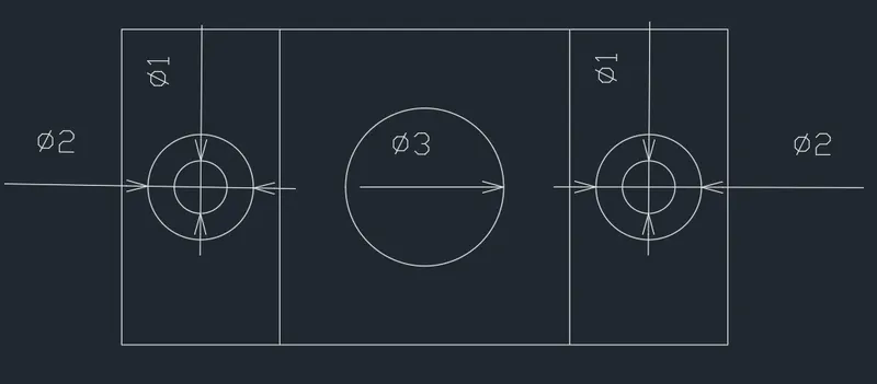
AIM:- To draw a geometry (using decimal units) according to provided drawing.
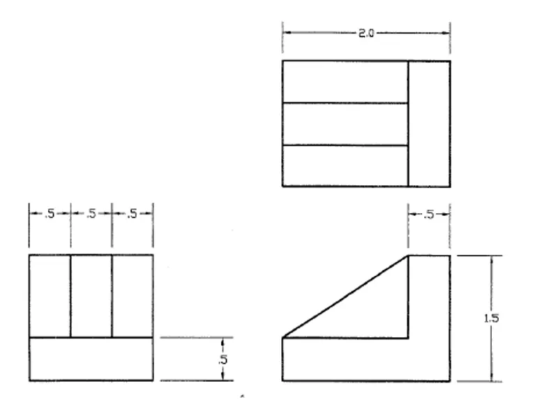
INTRODUCTION:-
To draw this geometry, I have used several autocad commands like- line,circle, offset, point etc., and I set dimension (Decimal) in Autocad. Moreover, I used both rectangular coordinate system and polar coordinate system to draw various steps in this drawing.
PROCEDURE:-
Open Autocad and type a command "Unit" and press enter, then set unit as decimal and set angle in degree- base angle is east -mark angle direction as anticlockwise. Type a command "DIMSTYLE" and press enter, then click to modify and go to primary unit tab and set it decimal and set the precision to 0.00 and cick ok.
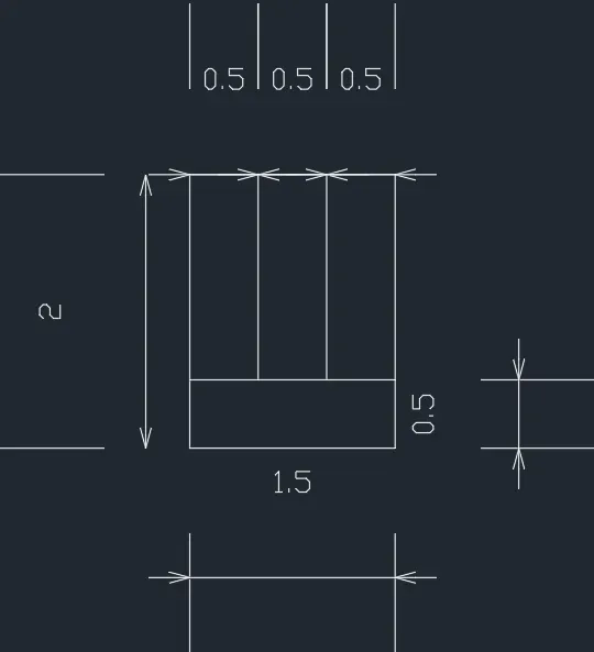
Step:-1
- Type a command "line" and provide a coorinate (0,0) then enter.
- Provide the next coordinate (@2<180) and enter.
- Provide the next coordinate (@1.5<90) and enter.
- Provide the next coordinate (@2<0) and enter.
- Type a command close and press enter.
- Type a command "offset" and press enter.
- Give offset value as 0.5 and press enter.
- Select right side line and set it left for one time.
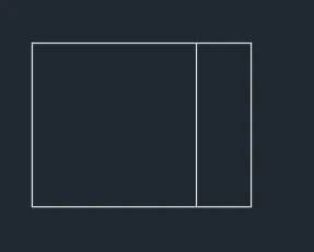
- Then select bottom line and move the cursor to top and left click in mouse.
- Then select previous line and move the cursor to top again and left click in mouse.
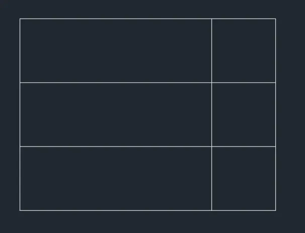
- Type a command "trim" and press enter, and right click on mouse and select right side edtended lines to trim off.
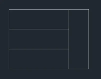
- Type a command "rotate" and select the whole object by 90 degree right.
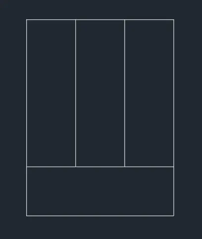
RESULT FOR STEP 1:-
FINAL SKETCH OF THE GEOMETRY.
Step:-2
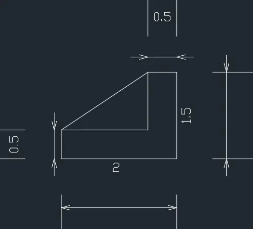
- Type a command "line" and provide a coorinate (0,0) then enter.
- Provide the next coordinate (@2<180) and press enter.
- Provide the next coordinate (@0.5<90) and press enter.
- Provide the next coordinate (@1.5<0) and press enter.
- Provide the next coordinate (@1<90) and press enter.
- Provide the next coordinate (@0.5<0) and press enter.
- Provide the next coordinate (@1.5<270) and press enter.
- Type a command "Line" and provide a coordinate (-2,0.5) and press enter.
- Provide the next coordinate (@1.5,1) and press enter.
RESULT FOR STEP 2:-
FINAL SKETCH OF THE GEOMETRY.
AIM:- To draw a geometry (using decimal units) according to provided drawing.
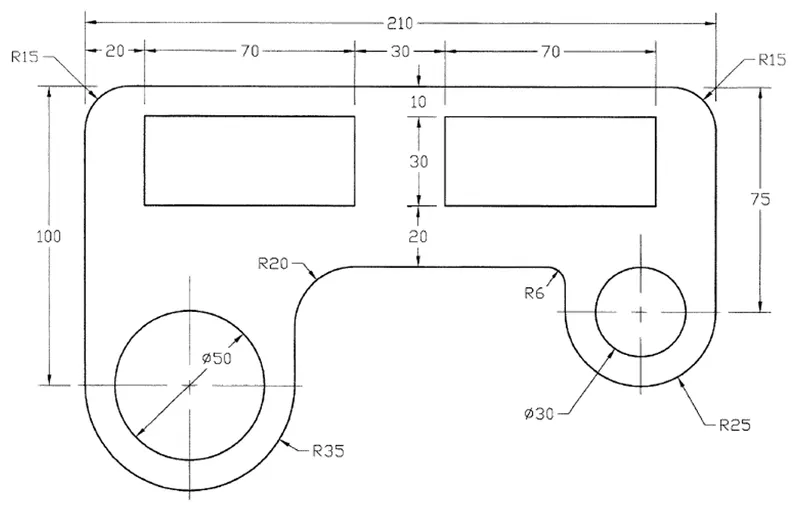
INTRODUCTION:-
To draw this geometry, I have used several autocad commands like- line,circle, fillet,arc,erase,offset, trim, etc., and I set dimension (Decimal) in Autocad. Moreover, I used the rectangular coordinate system to draw various steps in this drawing.
PROCEDURE:-
Open Autocad and type a command "Unit" and press enter, then set unit as decimal and set angle in degree- base angle is east -mark angle direction as anticlockwise.
- Type a command "circle" specify center and give radius 35 degree and draw another circle with same center with diameter 50.
- Draw a line from the center of those circles and give a coordinate (@25<180) and press enter.
- Draw line with command "Line" along the diameter of the circle and then vertically upwards give distance as 100 units by (@100<90) and press enter.
- Provide another coordinate as (@210<0) and press enter.
- After that give another coordinate as (@75<270) and press enter.
- Draw offset of 50 units (25+25=50, radius of arc) from the 75 unit line.

- By arc start, end, radius, draw an arc with the start point as the endpoint of 50 unit offset line and the endpoint of 75 units and give a radius of arc 25 units.
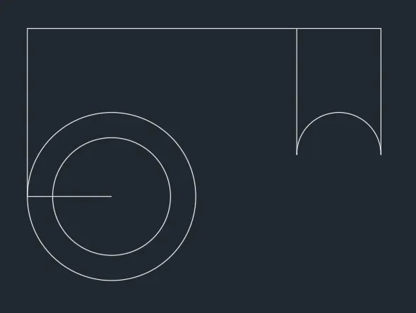
- Type a command "mirror" and select the arc the mirror it to opposite side without erasing source object.
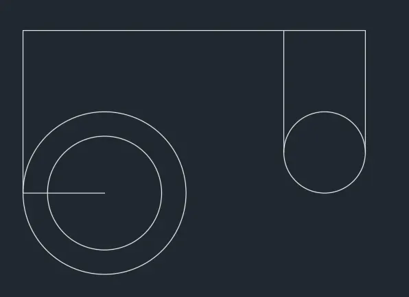
- By the same center, draw a circle of diameter 30 units.
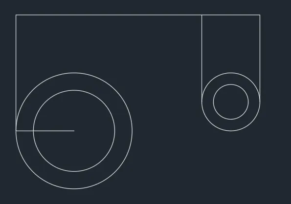
- Draw offset of 60 units from the top.
- From the extended line of 50 diameter circle of left side, draw a line perpendiculaly meeting the offseted line of 60 units.
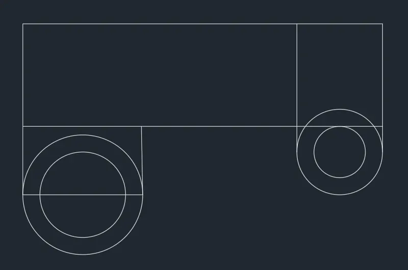
- Trim all the unnecessary lines according to given drawing.
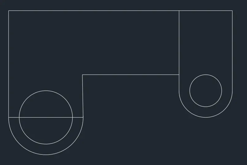
- Drawing rectangle.
- Give offset of 20 units from the left side figure and 10 units from the top for both sides.
- Then draw rectangle with command "rectangle" specify the corner point as intersection of offseted lines.
- Select "Dimension" and give the dimension as 70 units and 30 units(@70,-30) and press enter.
- Similarly on the other side copy the rectangle and specify the corner as that intersection point.
- Delete that offseted and unwanted lines.
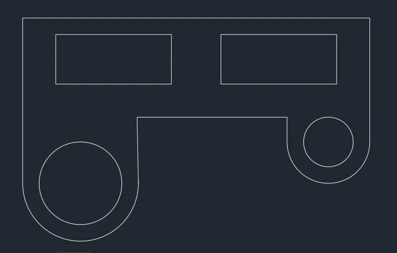
- Trim the part of circle of radius 35 units so that it forms an arc.
- Then fillet the corners:-
-Command "fillet" click on radius and give the radius, then select the two lines of which the corners are to be filleted.
- For the left and right side of the figure give 15 units as fillet radius.
- Give fillet radius as 20 units and 6 units in the bottom side.
RESULT:-
FINAL SKETCH OF THE GEOMETRY.
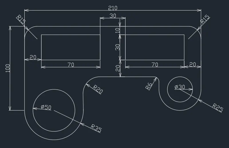
AIM:- To draw a geometry (using decimal units) according to provided drawing.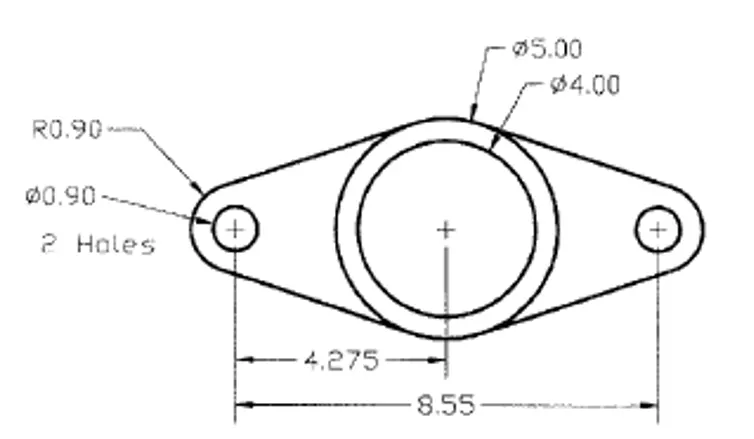
INTRODUCTION:-
To draw this geometry, I have used several autocad commands like- line,circle, fillet,arc,erase, trim, etc., and I set dimension (Decimal) in Autocad.
PROCEDURE:-
Open Autocad and type a command "Unit" and press enter, then set unit as decimal and set angle in degree- base angle is east -mark angle direction as anticlockwise.
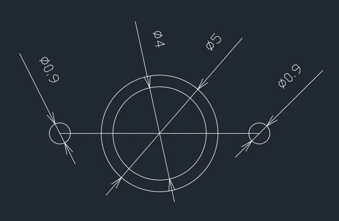
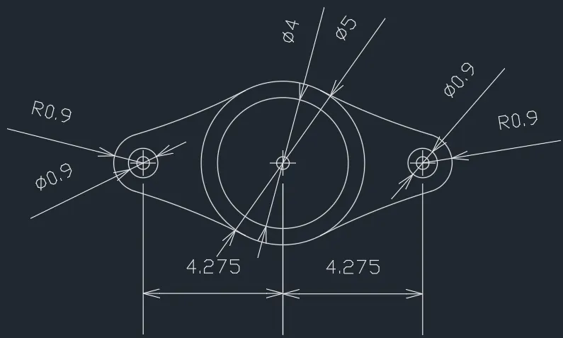
- Draw a circle of diameter 4 units "circle" - specify center - click on diameter - give 4 units.
- Draw another circle of diameter 5 units with same center - command "c" with osnap center on - specify the center - click on diameter give 5 units.
- Draw a line of 4.275 units from the center of circle - by the command "Line". - cursor is pointed to another direction and give 4.275 units.
- Consider this as the center of third circle with command "Circle" - specify the center end of line and click on diameter and give the diameter as 0.9.
- For the second side, with the same center of circle four, draw another circle with radius 0.9 units, command "circle" - specify center and give the diameter as 0.9.
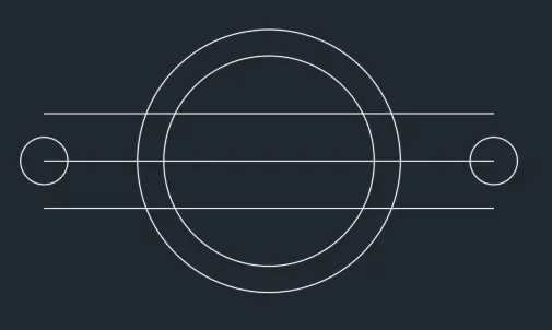
- Type a command "offset" and give unit to 0.9 and offset the central line both top and bottom side for left and right circle.
- By arc start, end, radius, draw an arc with the start point as the endpoint of both side offset line and give a radius of arc 0.9 units.
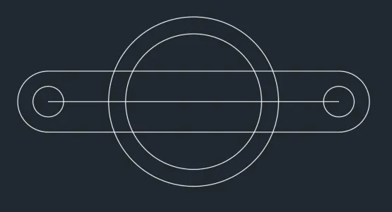
- Type a command "Fillet" and select left side arc and top side of 5 diameter circle and do the same for other three sides.
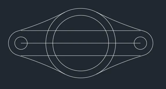
- trim and erase unnecessary lines.
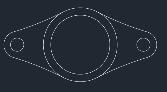
RESULT:-
FINAL SKETCH OF THE GEOMETRY.
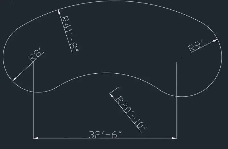
AIM:- To draw a geometry (using Engineering units) according to provided drawing.
INTRODUCTION:-
To draw this geometry, I have used several autocad commands like- line,circle, fillet,arc,erase, trim, etc., and I set dimension (Engineering) in Autocad and select 0'-00" and press ok. Moreover, I used both rectangular coordinate system and polar coordinate system to draw various steps in this drawing.
PROCEDURE:-
Open Autocad and type a command "Unit" and press enter, then set unit as engineering and set angle in degree- base angle is east -mark angle direction as anticlockwise.
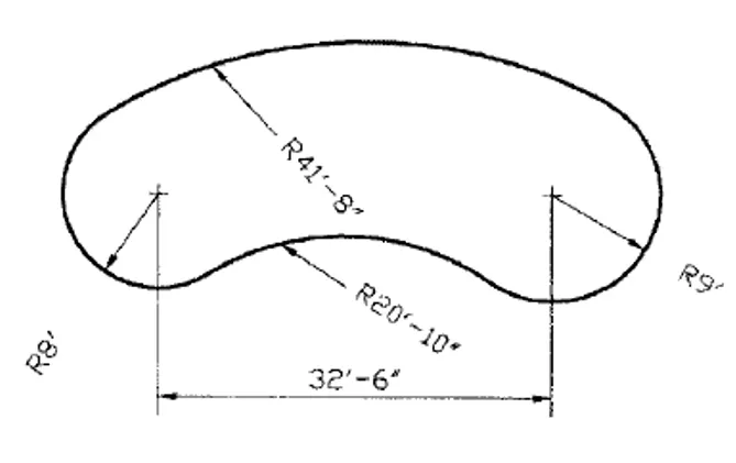
- Draw a line 32'6", then draw two circles of radius 8' and 9' with center as 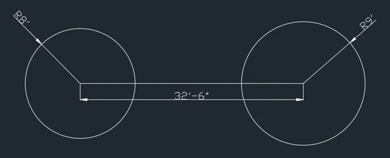
- To draw the bottom arc, draw offset to both the circles with offset distance as radius of the bottom arc.
- Command "offset" - select the circle - give offset distance as 20'-10".
-We will get an intersection of the two circles, from the intersecting point draw a line to the center of the circle of radius 8' and 9'.
- The line meeting the circles will act as the tangent of the circle and its distance will be 20'-10" same as the radius of arc.
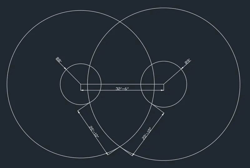
- Draw a circle with center as intersection point of the offseted circle and radius of 2'-10".
- It will pass through the tangent points.
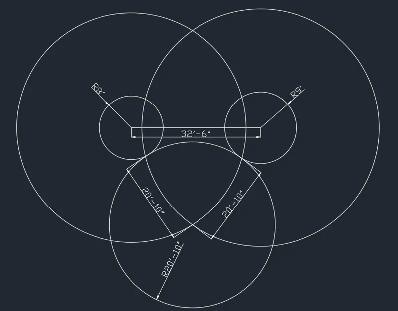
- Trim the rest of the figure to get an arc and thus an arc of 20'-10" will be formed.
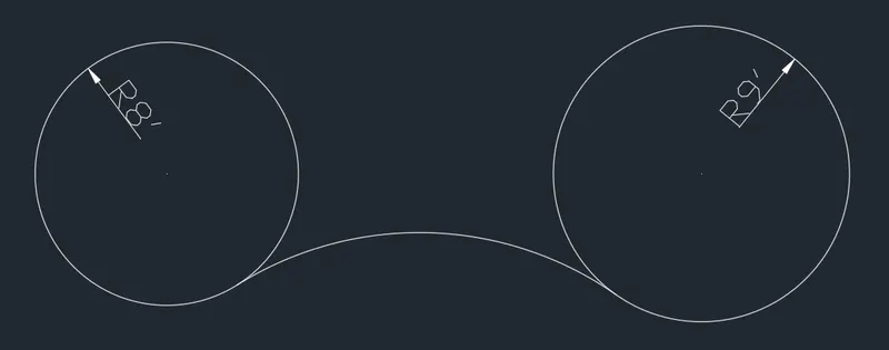
- To draw the upper curve,
- Draw a circle with radius 32'8" (41'8"-9'= 32'8") with center same as that of radius 9' circle.
- Draw another circle with radius 33'8" (41'8"-8' =33'8") with center same as that of radius 8' circle.
(So that the distance from the newly drawn circle to the upper side of radius 9' and 8' circle will be 41'8")
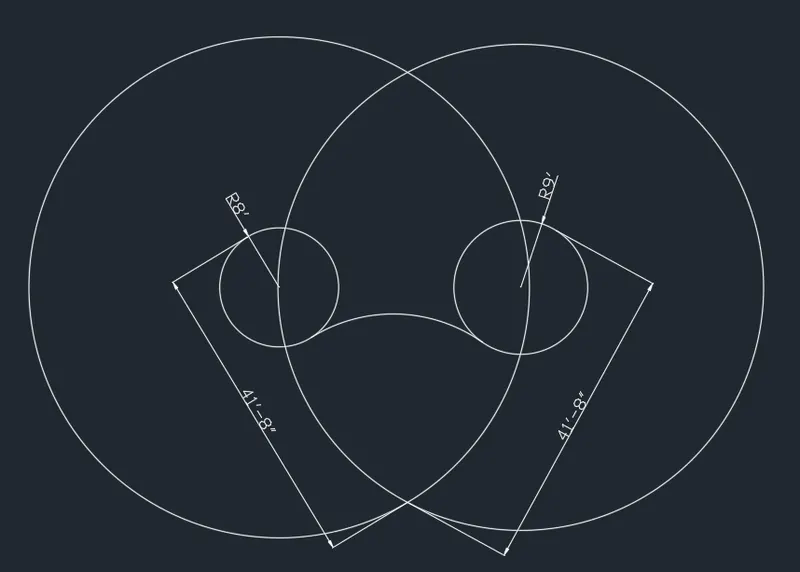
- Draw the perpendicular lines from the bottom intersection of both circles and through the centre to top of the circle of radius 8' and 9', which indicates the tangent points.
- Draw another circle, with center as the intersecting point of the bottom circles and with radius 41'8".
- It passes through the tangent lines drawn earlier.
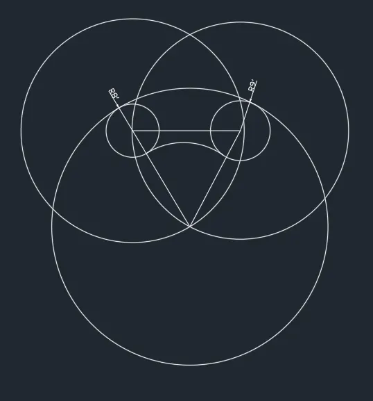
- Trim off and reset the rest, so that an arc of radius 41'8" is formed between the tangents.
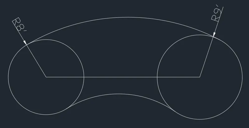
- Trim the part of the circle and the line connecting the center of circles.
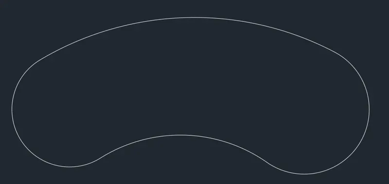
RESULT:-
FINAL SKETCH OF THE GEOMETRY.
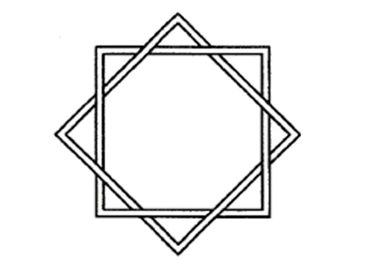
AIM:- To draw a geometry (using decimal units) according to provided drawing.
INTRODUCTION:-
To draw this geometry, I have used several autocad commands like- line, rectangle,offset etc., and I set dimension (Decimal) in Autocad and select 0.0 and press ok. Moreover, I used both rectangular coordinate system and polar coordinate system to draw various steps in this drawing.
PROCEDURE:-
By rectangle tool draw square.
- Command "Rectangle" - Specify the point where we need to draw - click on "diamension" - here I have taken as length= 6 units and breadth= 6 units (@6,6).
- Take offset of 0.2 units outside the rectangle, command "offset" - Specify the distance= 0.2 units.
- Create another rectangle as same size as in first step
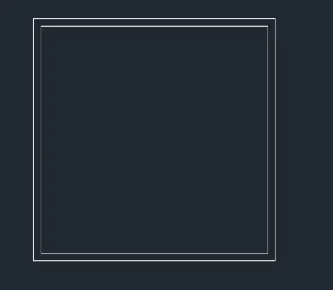
- Copy this square, so that two square are created.
- Rotate the second square by command "ROTATE" - Select the object - Specify the base point - bottom point(The point by which we need to rotate) and rotate it by angle 45 degree.
- With OSNAP on move the rectangle by command "Move"- select the object- specify bas point (here base point is selected as center of square) and is moved and placed on center of the first square by using OSNAP center on.
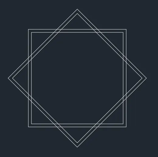
RESULT:-
FINAL SKETCH OF THE GEOMETRY.
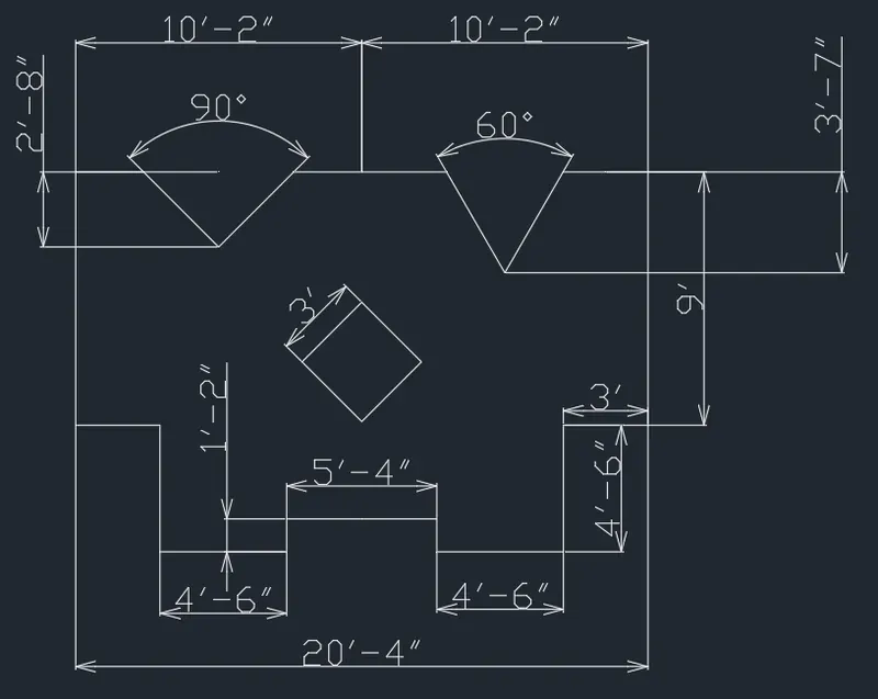
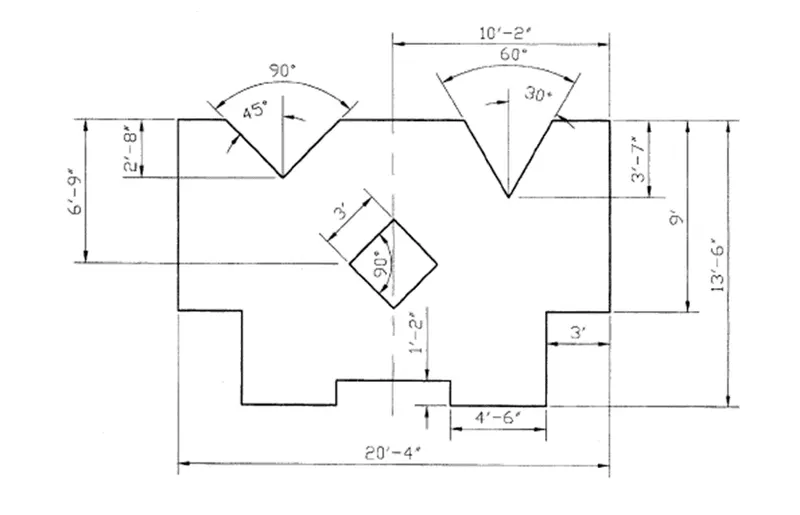
AIM:- To draw a geometry (using decimal units) according to provided drawing.
INTRODUCTION:-
To draw this geometry, I have used several autocad commands like- line, polygon,trim, erase, offset etc., and I set dimension (Engineering) in Autocad and select 0'-0" and press ok.
PROCEDURE:-
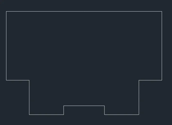
By using line command, draw the outline
- Command "Line" - give the distance of 2'8"(10'2"-(4'6"+3')) to +x direction.
- With cursor pointing to -y direction give a distance of 1'2"
- With cursor pointing to +x direction draw a line of 4'6"
- With the cursor pointing to +y direction draw a line of 4'6" (13'6"-9')
- Draw 3' in +x direction.
- Draw 9' in +y direction.
- Draw 10'2" in -x direction.
- Type a command "close" and press enter.
- With command "Mirror" mirror the image, command "Mirror" - select the object - select the base point and give the mirror line to left side, and click no - so that the original object won't get erased.
- Erase the center line twice.
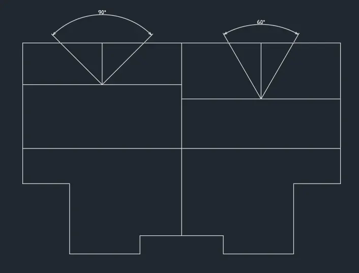
- Give the offset line of distance 3'7" horzontally by offset command "O"
- With midpoint of 10'2" draw a vertical line of length 3'7"
- Draw lines on both sides such that the included angle is 60 degree 30 degree on both side of the vetical line.
- Similarly on the other side, locate the midpoint, draw a vertical line of 2'8" and draw the inclined lines such that the included angle is 90 degree.
- Draw a line vertically downwards from the midpoint on the object (10'2") and offset the top line at a distance of 6'9" so that the center point of the square is located.
- With command "polygon" draw a polygon of 4 sides, specify center and give radius as 1'-6" circumscribed inside a circle.
- Rotate the polygon to 45 degree with base point as center.
- Erase all the lines used for reference.
RESULT:-
FINAL SKETCH OF THE GEOMETRY.