Structural Modelling using Etabs 2018
STRUCTURAL MODELLING USING ETABS 2018
AIM:
- To model and analyze the G+7 residential building from the given architectural drawings using the ETABS 2018.
- To Run a modal response spectrum analysis and check analysis results of the Etabs model for inter-storey drift requirements, vertical & planar irregularities, minimum shear wall requirements, maximum axial load ratio for column and shear walls, effective moment of inertia for beams and columns etc.
INTRODUCTION:
- ETABS is an engineering software product that caters to multi-story building analysis and design.
- Modeling tools and templates, code-based load prescriptions, analysis methods and solution techniques, all coordinate with the grid-like geometry unique to this class of structure.
PROCEDURE:
-
First we have open the etabs software.
-
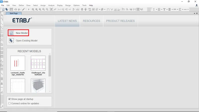
Then click on the New model option at the left side to create the new model, as shown below.
-
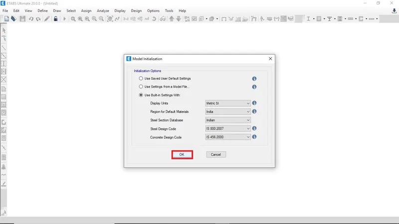
After that model initialization window will peompt, we have to select 'Use Built-in Settings with' option, as shown below
-
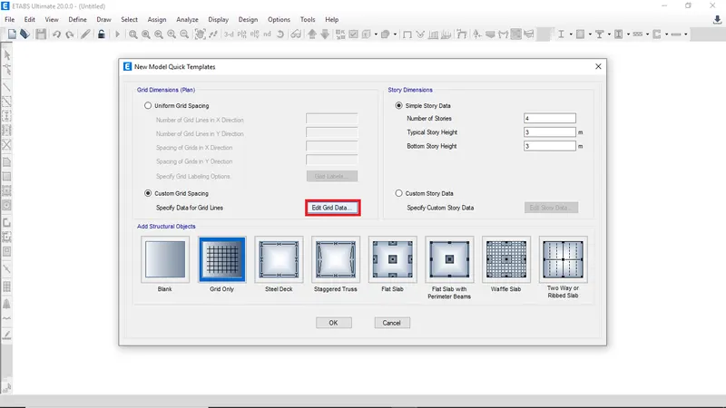
Then choose grid only to create grids, to add grids click on edit grid data
-
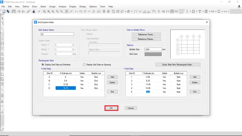
Enter the X and Y grid data use add button to add extra grids and enter their respective distance
-
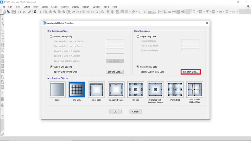
Then click on edit storey data to add number of story and story height
-
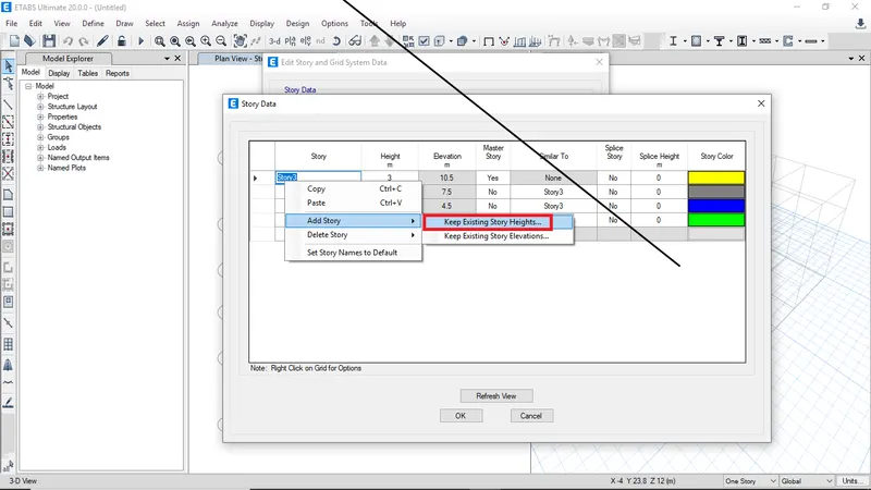
In the below image we can see, by right click and select the keep existing storey height to create more story
-
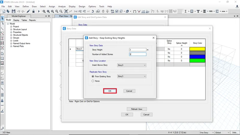
Enter the required number of story and their height then click ok
-
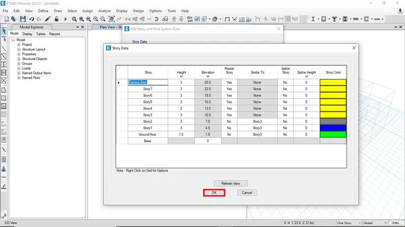
After entering all details and creating the requiries story then click ok
-
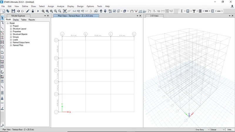
This is the first etabs user interface. In the left side its the plan view and in the right side its 3d view
-
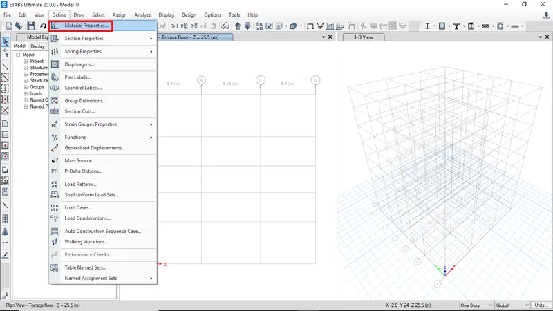
Firstly need to define the material properties, so click on material properties to in define from menu bar to define the material properties
-
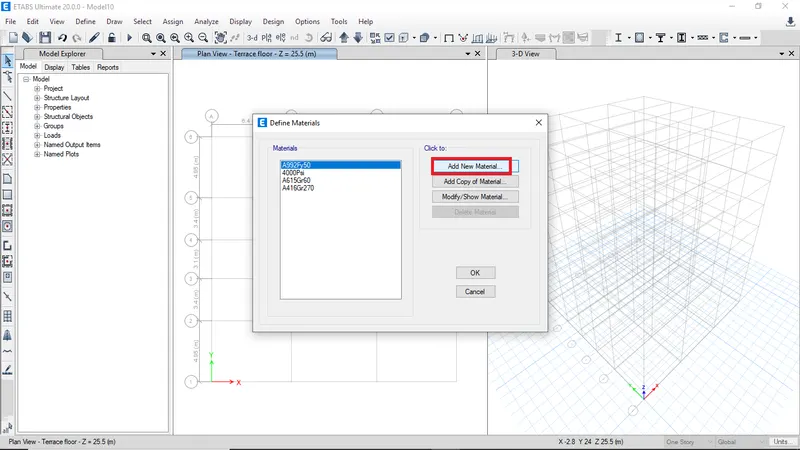
To add new material property click on add new material
-
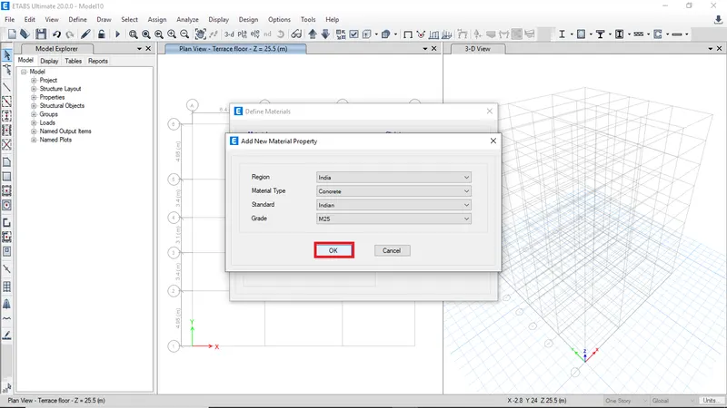
Then in the opened window select the desired material properties and click ok to create the material
-
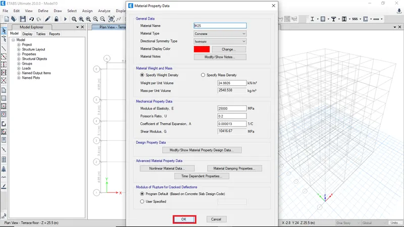
Then it opens the detailed material property data
-
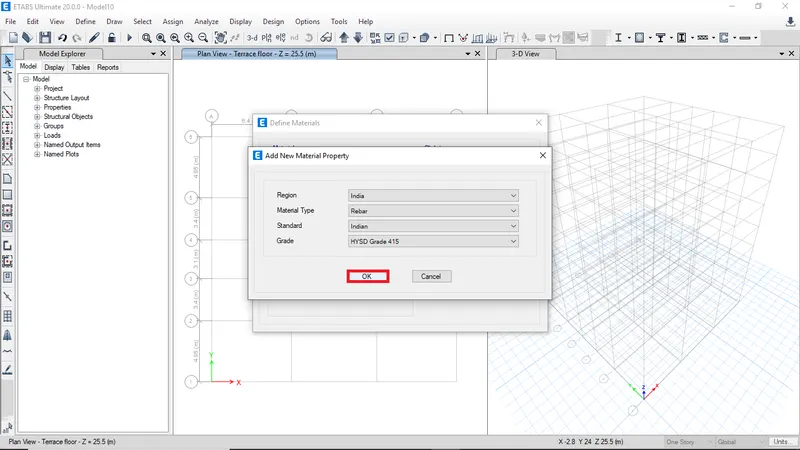
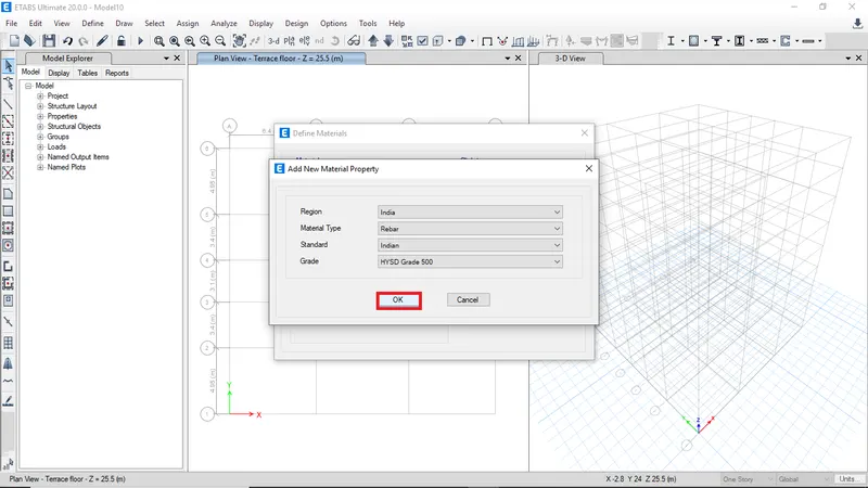
in the similar way create rebar material and click ok
-
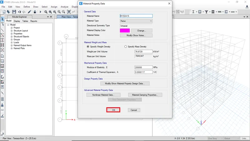
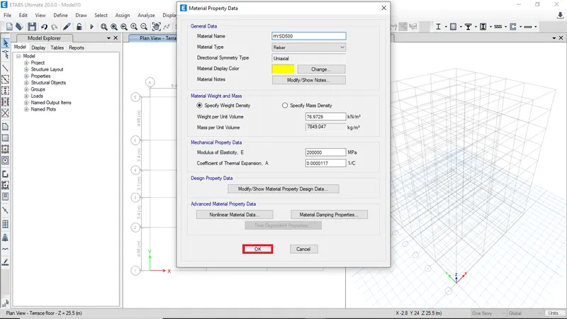
The detailed material property data will open and then click ok
-
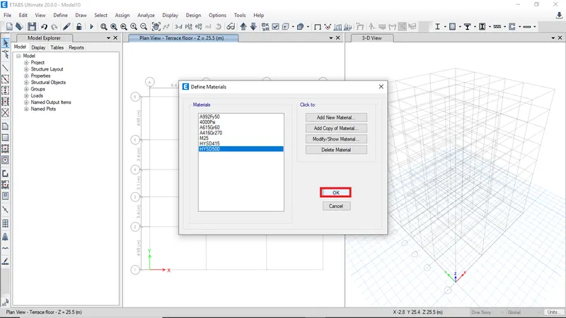
After creating all the material properties click ok to finish
-
After creating the material properties need to define frame sections
-
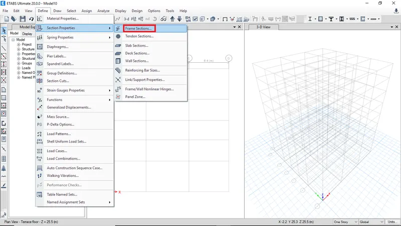
To create frame sections go to define and click on frame section in section properties
-
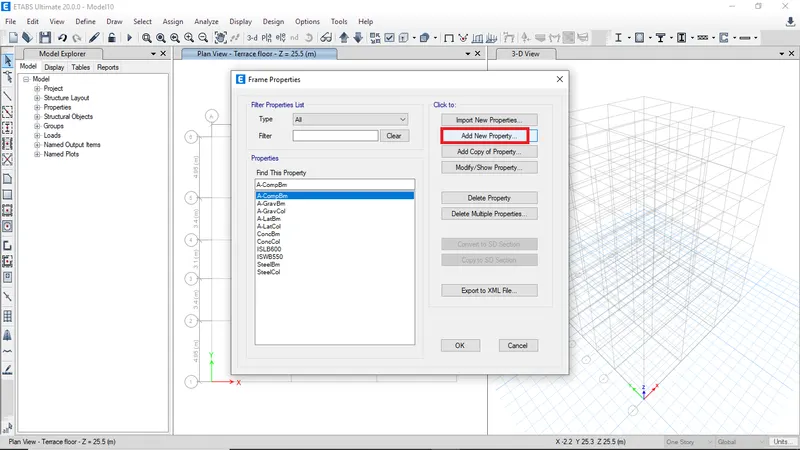
To define new frame property click on add new property
-
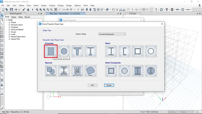
Slect the rectangular section then click ok
-
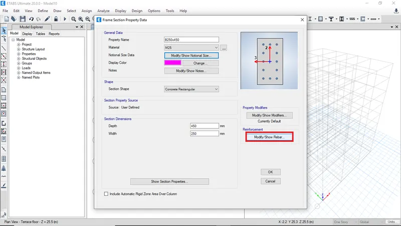
Enter the property name for each frame sections and choose the material grade
-
Enter the depth and widt of the sections
-
click on modify rebar data to specify the rebar data
-
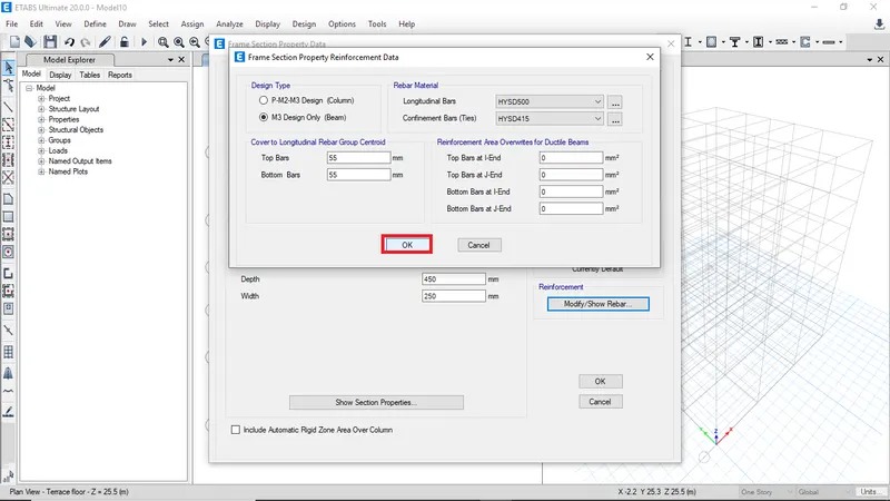
In that choose design for baem if its a column section then choose column
-
For this section its a beam so click on beam and enter cover details
-
Also specify the rebar materilal from the dropdown selection
-
After entering all the details click ok
-
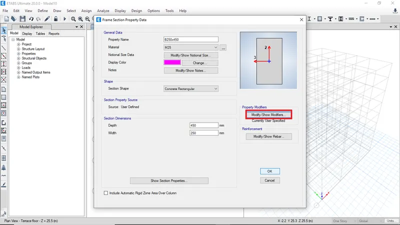
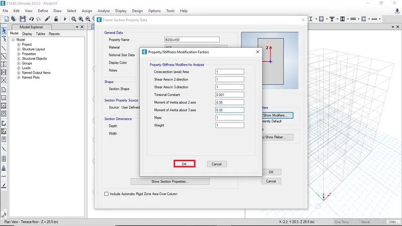
click on property modify to modify the beam peoprty
-
Enter the details as shown in below image
-
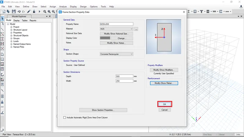
In the same wat create another beam section with respective property name and all the details
-
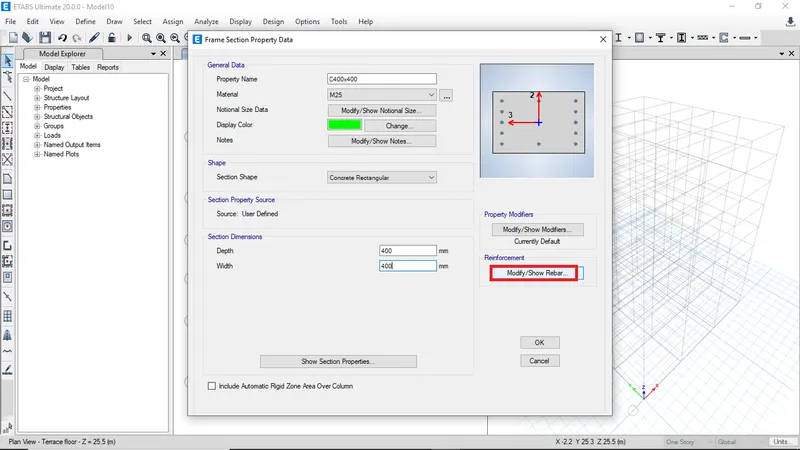
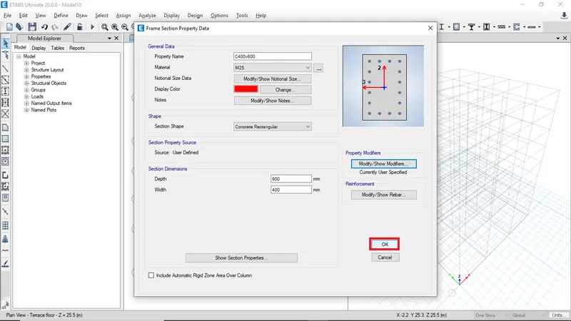
For the column section enter the property name and choode material
-
Then enter the depth and width values
-
Click on modify rebar data to enter the rebar details
-
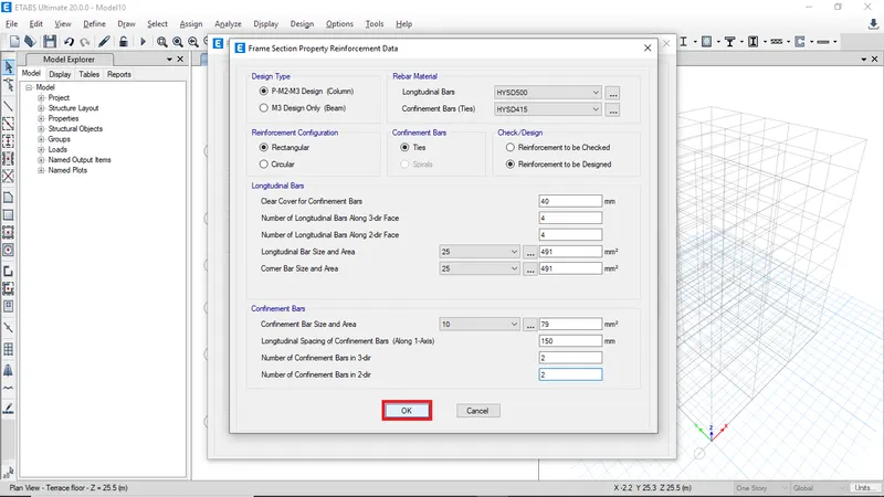
Choose design type as column design
-
Then select reinforcement configuration as rectangular
-
Choose the correct mngitudinal and confinement bars from the dropdown
-
Enter the cover and bar diameter details then click ok
-
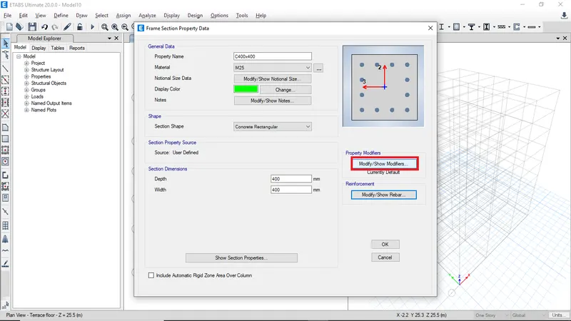
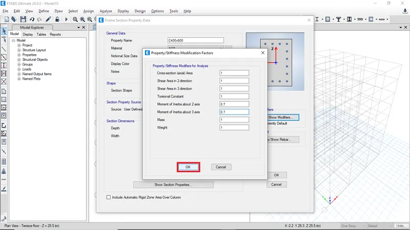
Click on propetry modifier to modify column peoperty
-
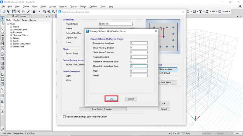
Enter the details of the column as shown in below image
-
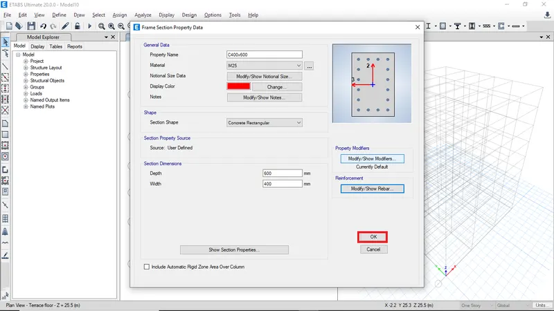
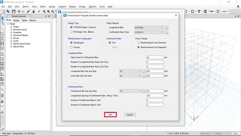
by following same procedure create the define the column sections
-
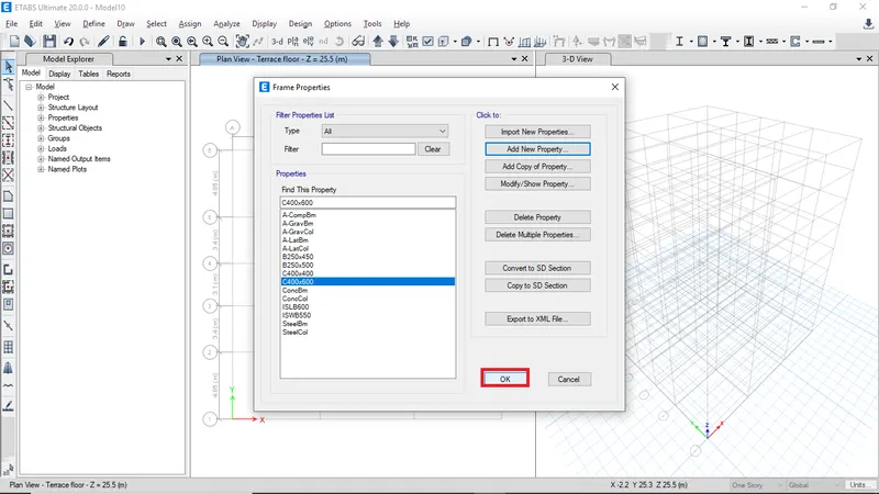
After adding all the frame properties click ok to finish
-
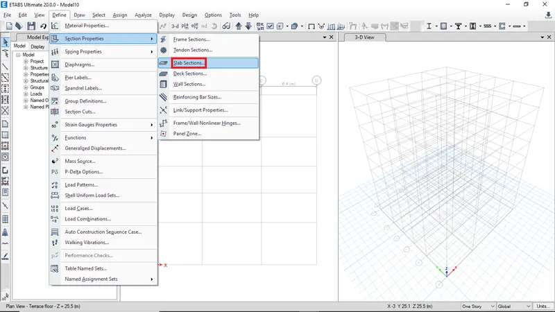
Then need to define slab sections
-
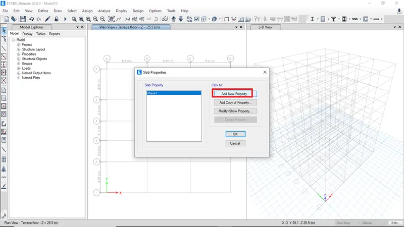
For that go to define and select slab sections in sections peroperties
-
click on add new property
-
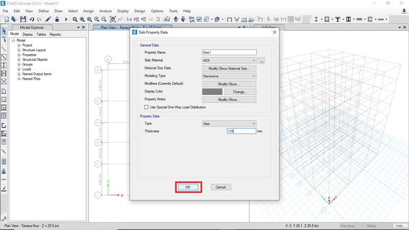
Add peoperty name for slab
-
Select the slab material
-
And choose modeling type as membrane
-
Then enter the thickness of the slab
-
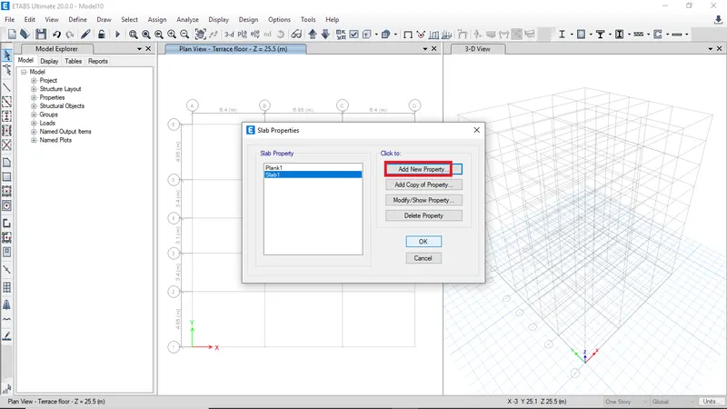
Create anothe slab by clicking add new property
-
Then click ok to to finish defining slab sections
-
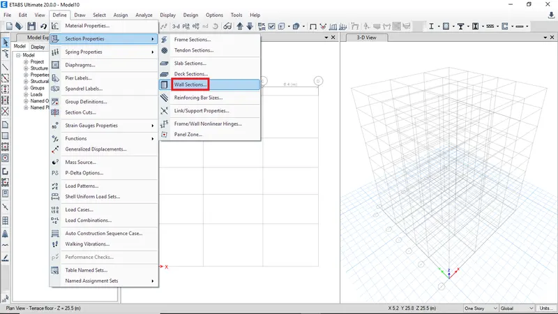
After that need to define property for shear wall
-
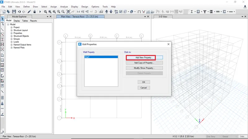
For that go to define click on wall sections in section properties to define shear wall peoperties
-
Click on add new property to t define shear wall property
-
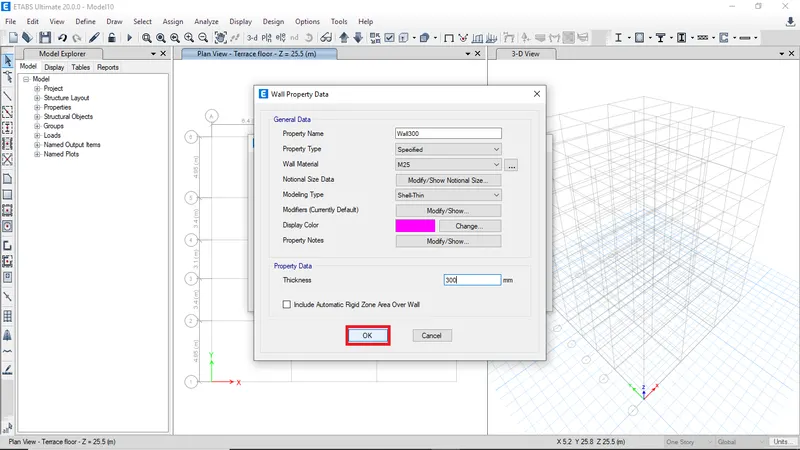
Enter the property name and select the wall material type
-
Select modeling type as shell-thin
-
Enter the wall thickness and click ok to finish
-
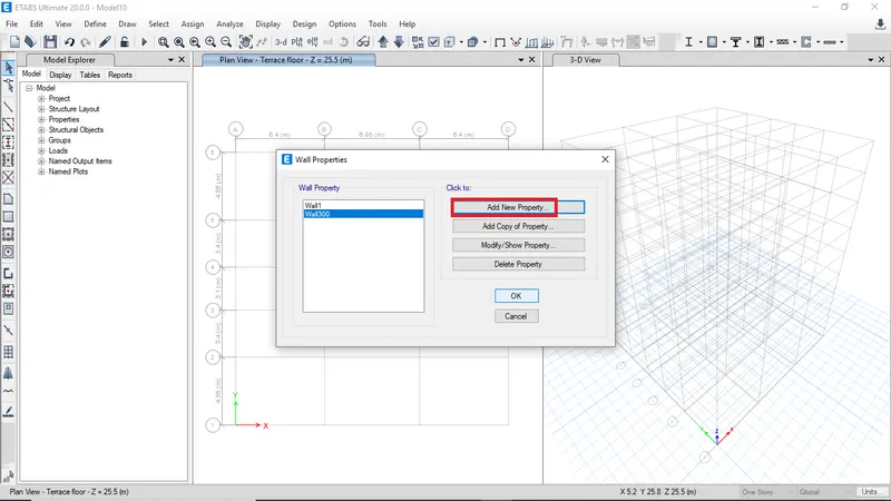
After defining all the walls, click ok to finish
-
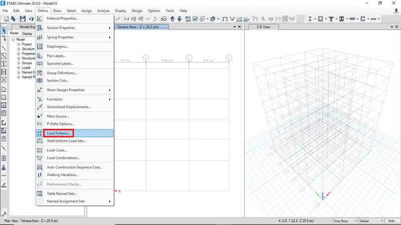
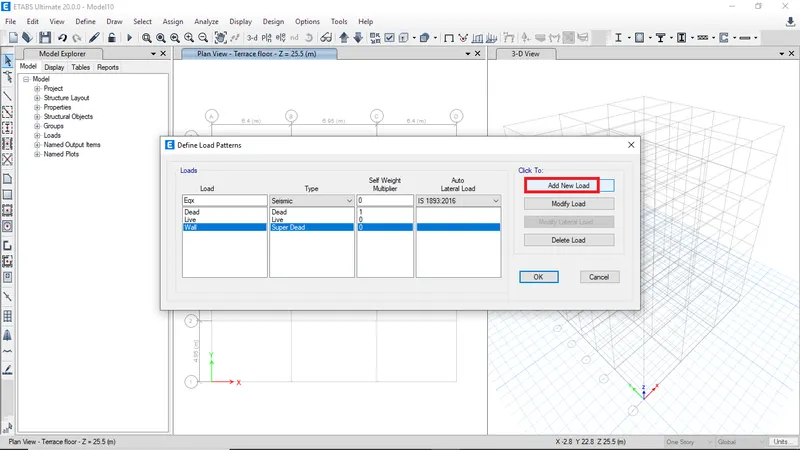
To define load pattern click on load pattern on in define in menu bar
-
click add to add the new loads
-
Select the type of load and code from the dropdown
-
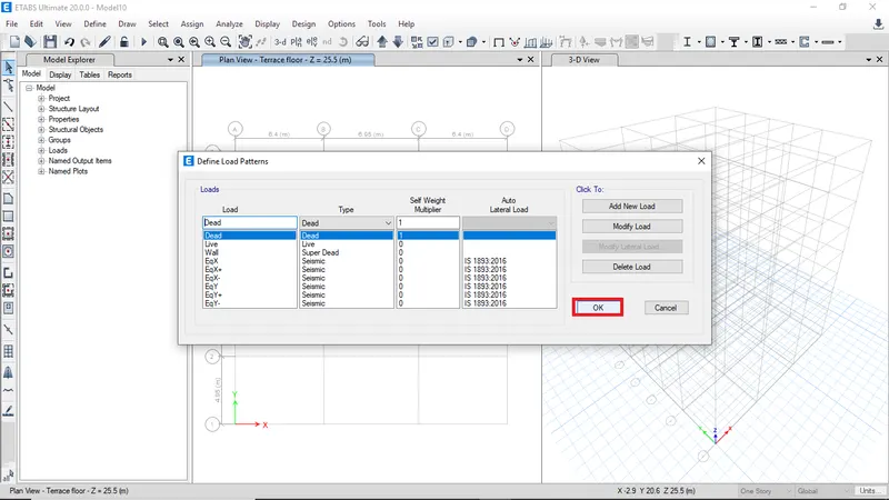
After add all the load types click ok to finish
-
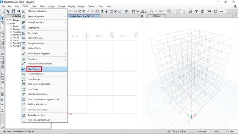
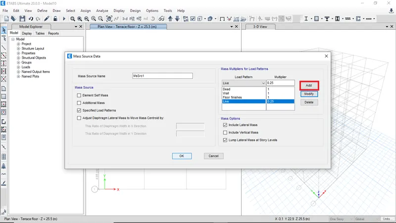
Then we need to define the mass source
-
Fo that go to define and click on mass source
-
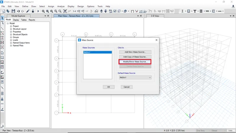
The mass source is already present to modify click on modify
-
In that select specified load pattern and add the load pattern with the respective multiplier
-
After defining all the sections, materials and load patterns need to start modeling
-
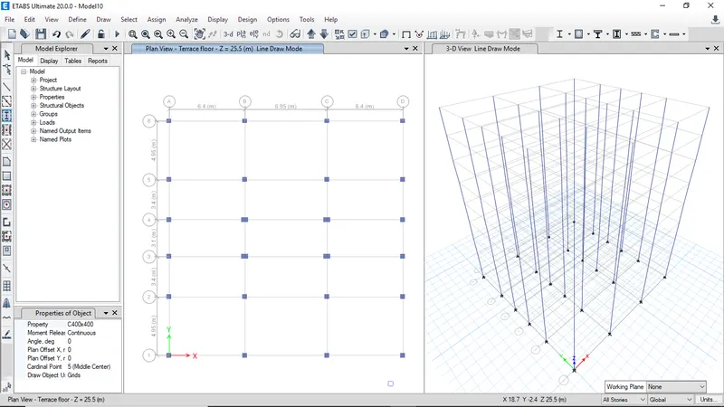
First to ceate columns click on quick draw column in the left side window
-
Befire that make sure the work mode is switched to all stories
-
Then select the column property to draw and draw the columns as per their respective positions
-
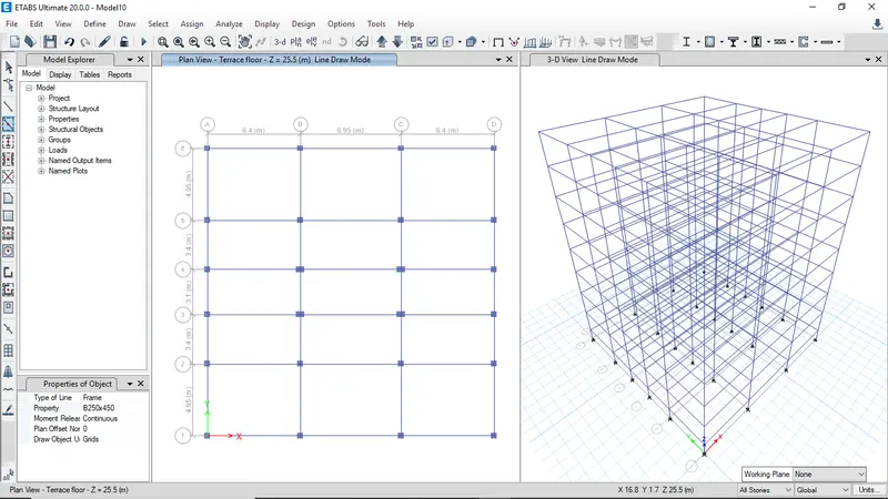
In the same manner create the beams by clicking quickdraw beams in left side panel
-
The beams need to draw in all stories mode
-
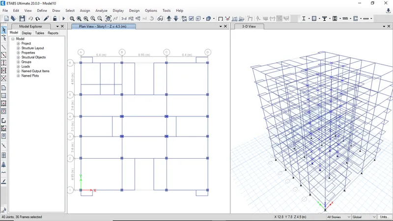
Add the secondary beams with respective to peoper dmensions
-
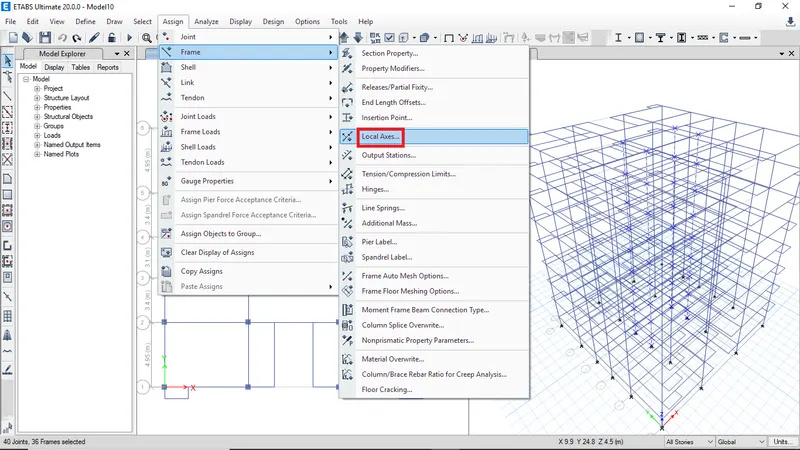
To rotate the columns select the columns in the window
-
Then go to frame and click on local axes to rotate column
-
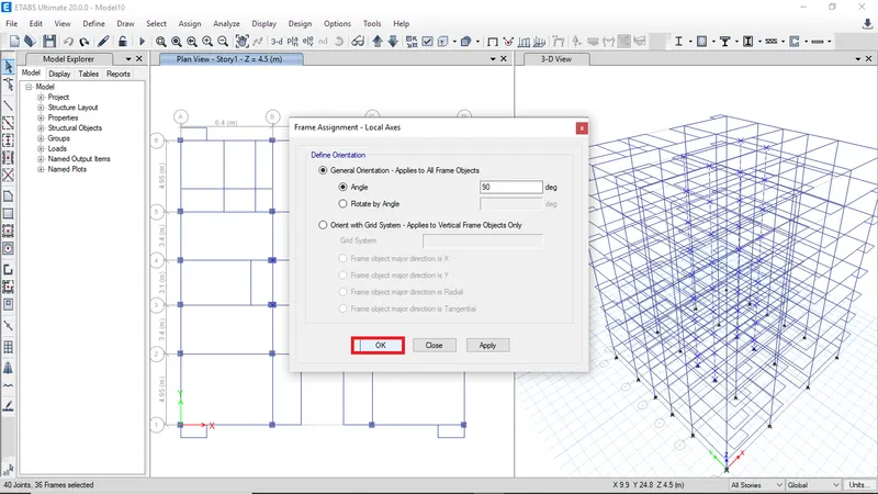
Enter the angle in degree to rotate
-
Then click ok to rotate the column
-
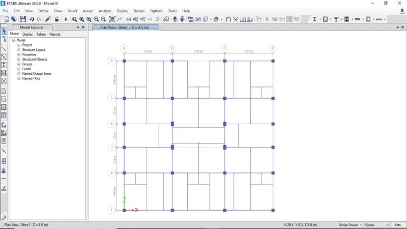
All the column orientation is updated
-
cross check again to confirm
-
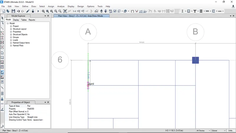
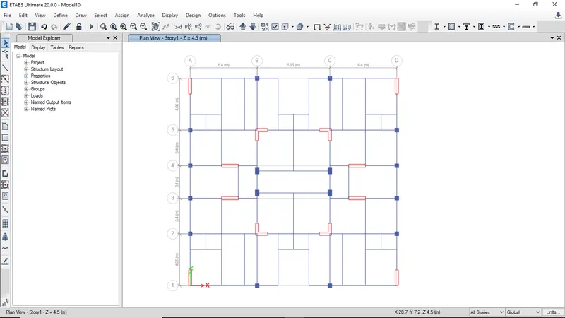
Click on draw wall to draw the shear wall
-
Draw the shear wall with respect to their location and length
-
The below image shows all the shear walls
-
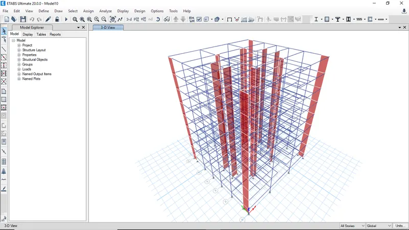
The 3d view of the model
-
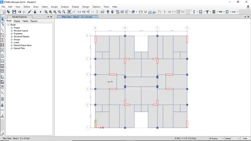
After adding the frames need to draw slabs
-
Use quick draw to draw slabs quickly
-
In place of cut slabs use poly draw slab
-
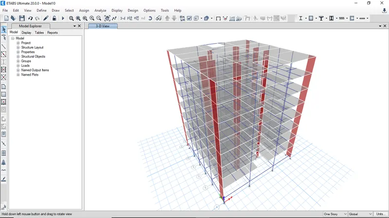
The final 3d model is shown below
-
Now need to assign loading for analysis
-
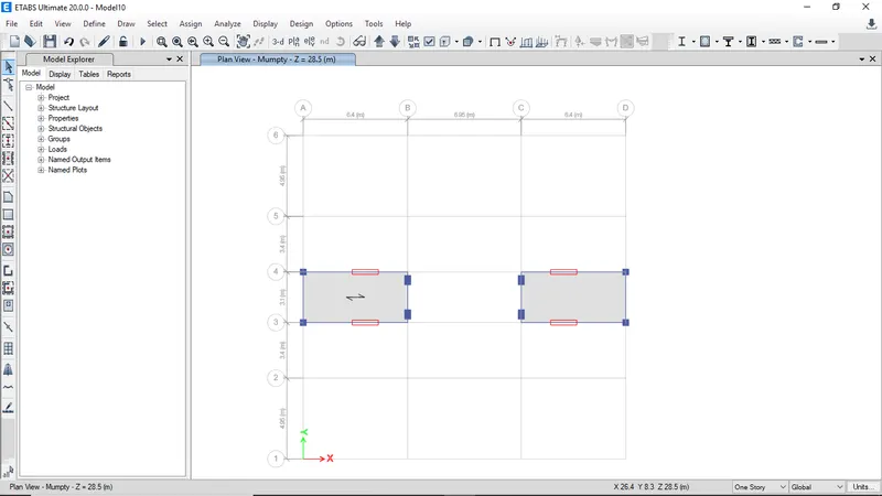
In the mumpty level draw the slab and assign one way load distribution on stair
-
To assign the loads now need to select frames
-
The wall load is acting only on frames so selct the frames
-
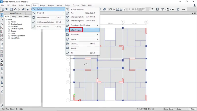
The frames are selectes by using object type
-
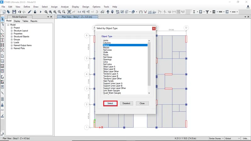
select beams and click select
-
Now all the beams are selected
-
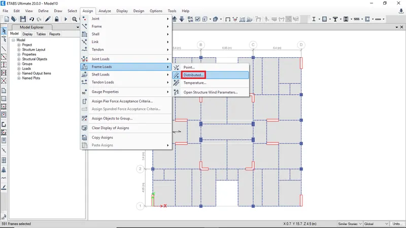
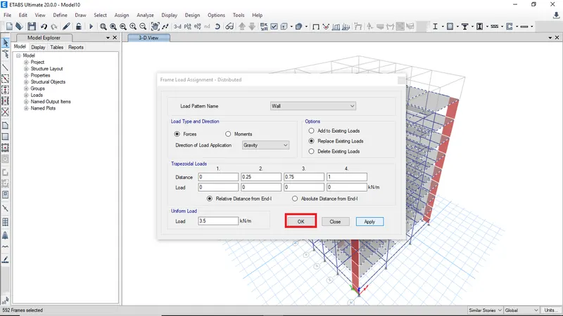
Go to assign, click on distributed load in frame loads in frame load
- Select the load pattern as wall
-
Enter the uniform load value and click ok to assign
-
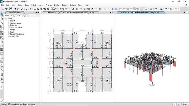
The assigned load will be visible in the given image
-
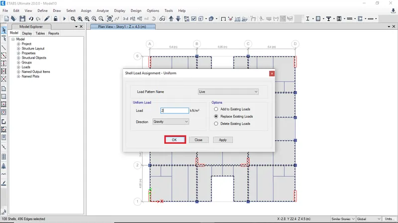
In the similar way, select the slabs to assign the live load
-
Dont select the stair and lift slab
-
Assign live load as 2 and also floor finish load
-
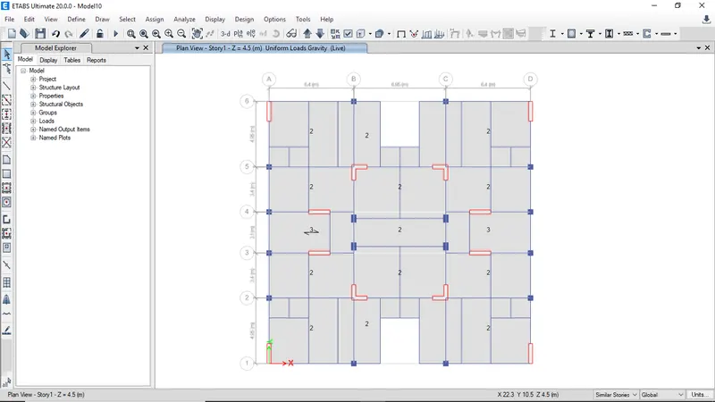
The assigned load is visible
-
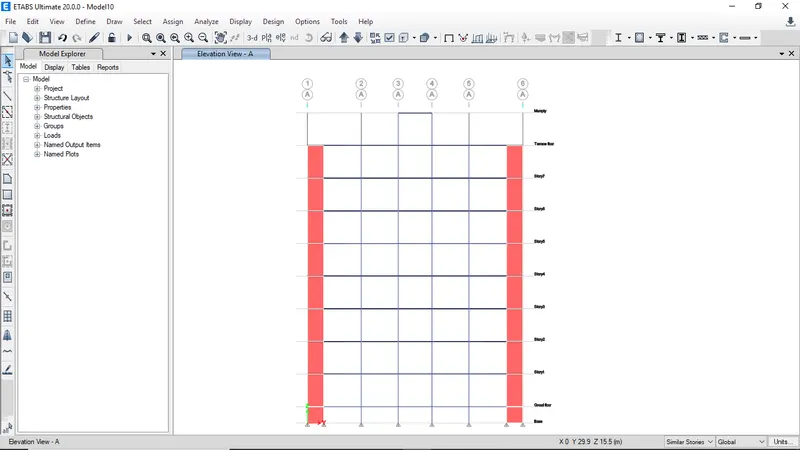
The below image shows the elevation of the model
-
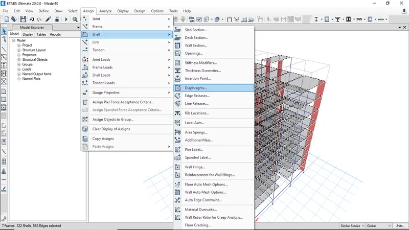
For slabs we need aggign the diaphragms
-
Select the slabs using object selection
-
Then go to assign shell and click on diaphragms
-
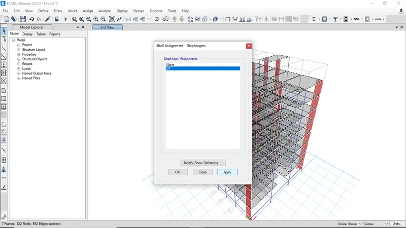
Click on d1 and click apply
-
Click ok to finish
-
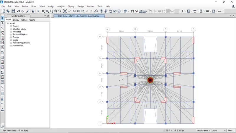
The assigned mass source is visible
-
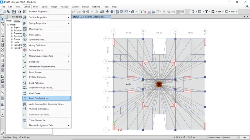
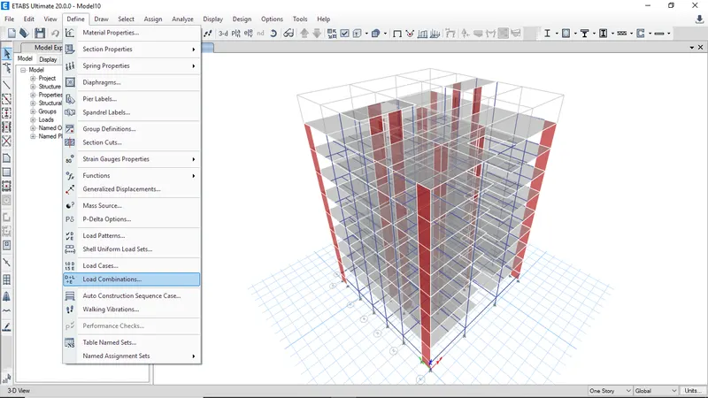
To define the load combination, go to define and click on load combinations
-
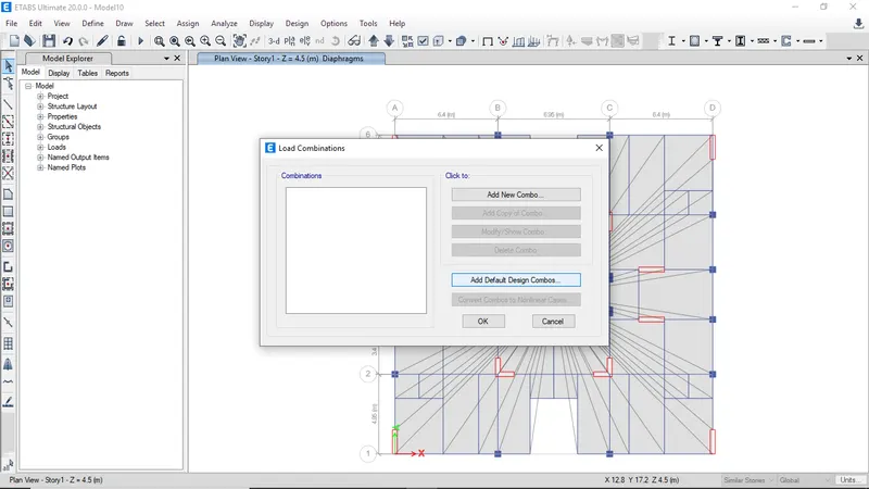
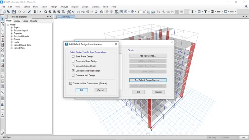
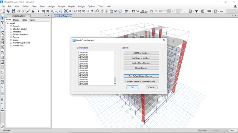
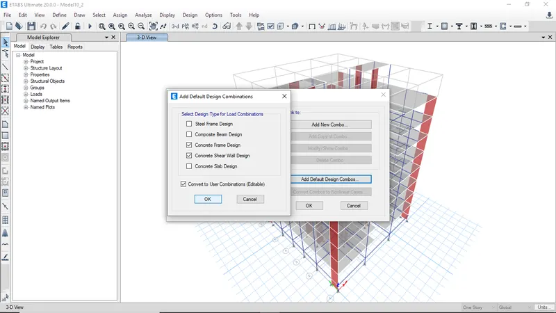
click on add default design combo
-
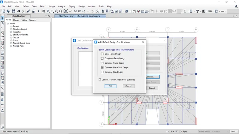
Then slect concrete frame design and shear wall design to add load combinations
-
Also click on convert to user combination to edit them
-
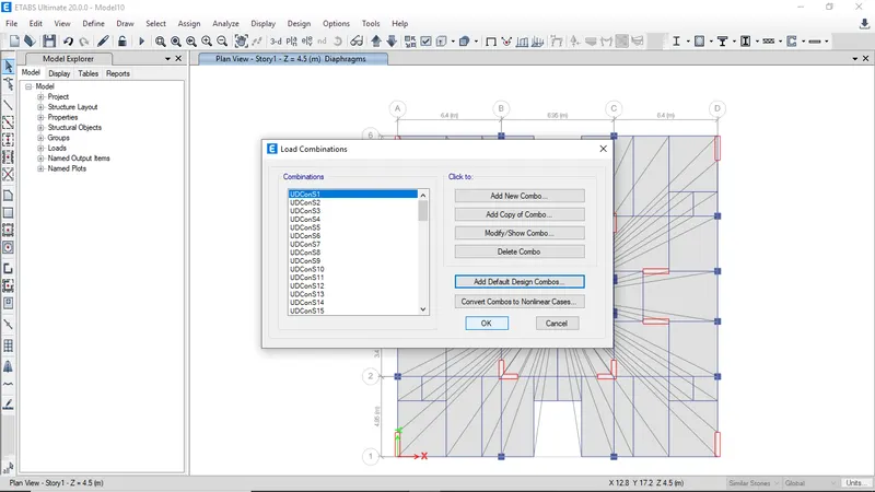
After creating all the load combinations click ok
-
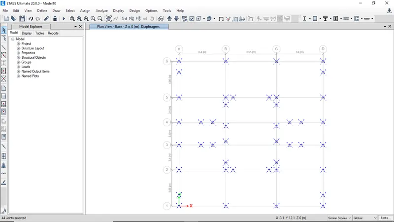
Switch to base plan view
-
select all the column to assign support
-
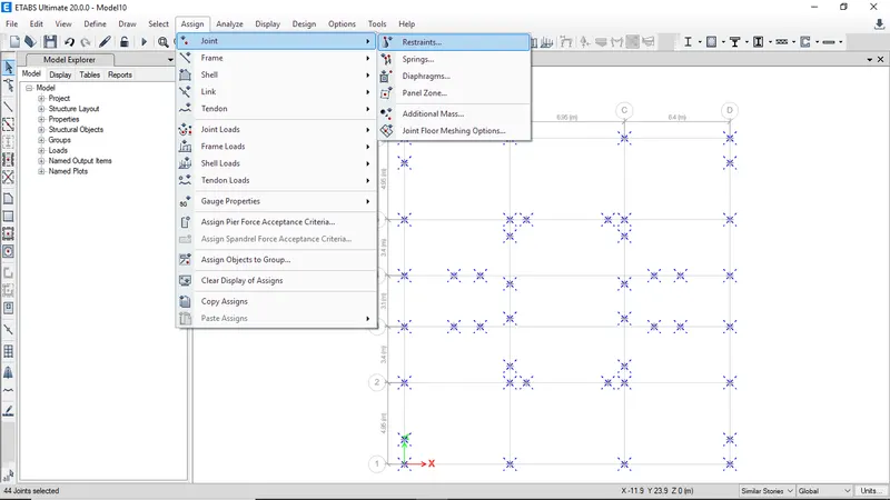
To aggign support go to assign click on restraints in joints
-
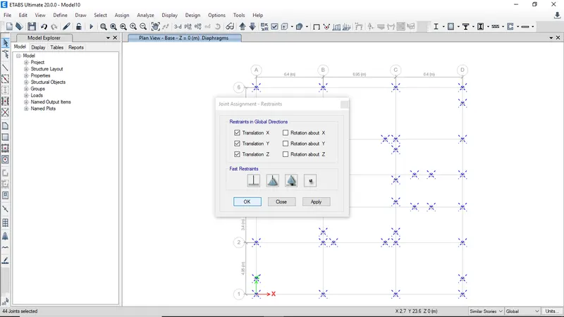
then select fixed restraint and click ok
-
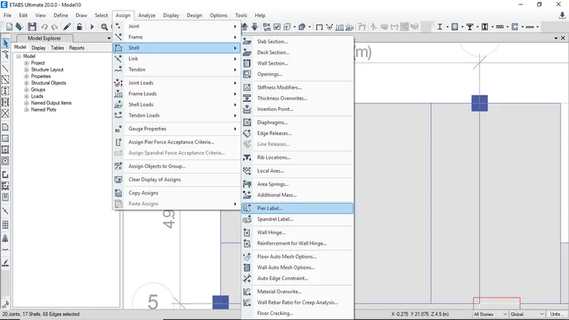
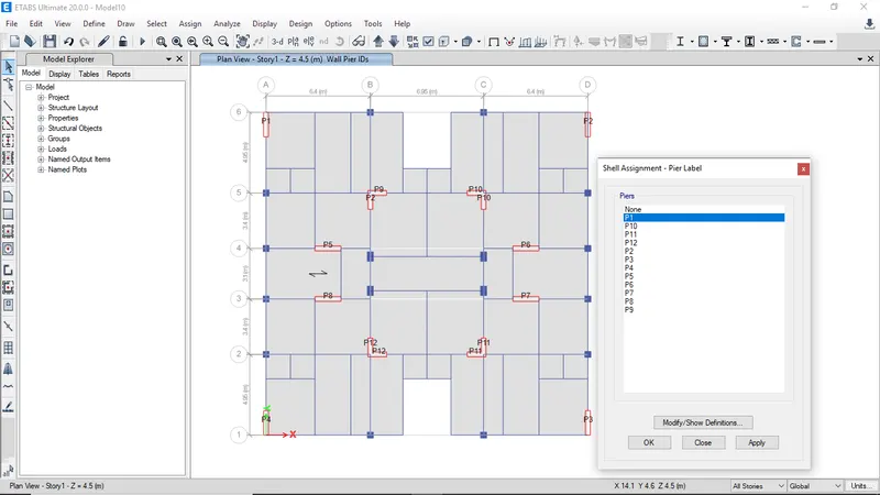
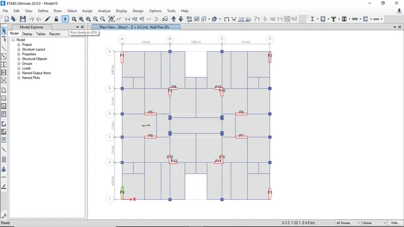
To assign label to the shear walls go to assign and click on pier label in shell
-
Click on modify to add more label
-
Select each shear wall and assign the pier label
-
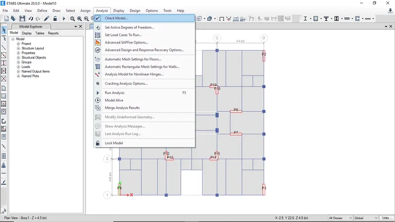
After assigning all the loads need to check the model for error
-
Click on Check model in analyse tab
-
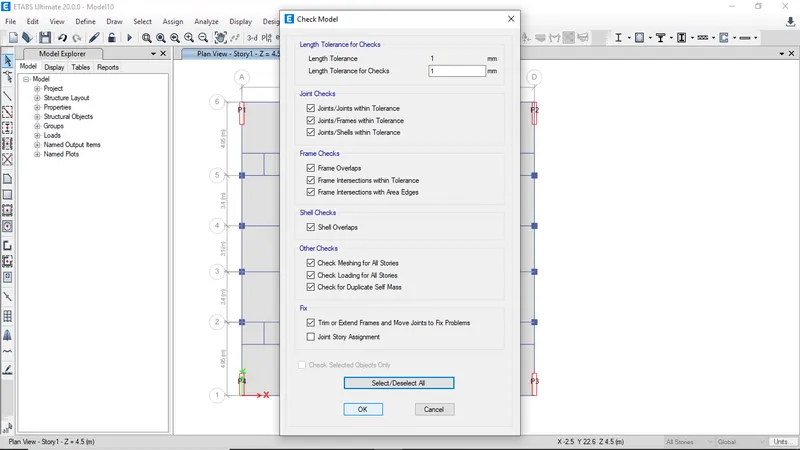
Click on select alland click ok
-
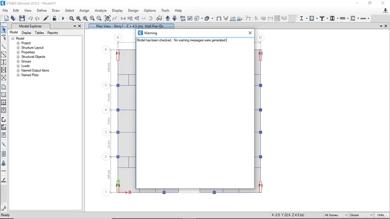
After checking it shows no error if error found then need to correct them
-
Then click on run analysis
-
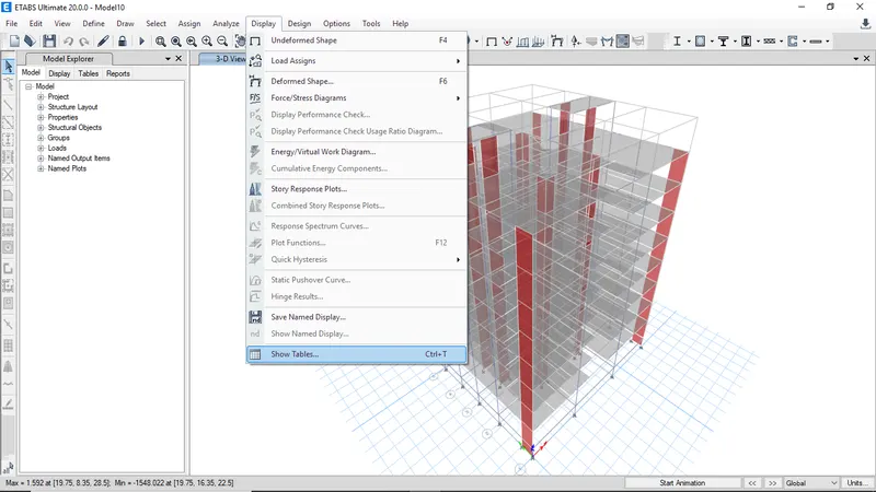
Go to display and click on show tables to view results
-
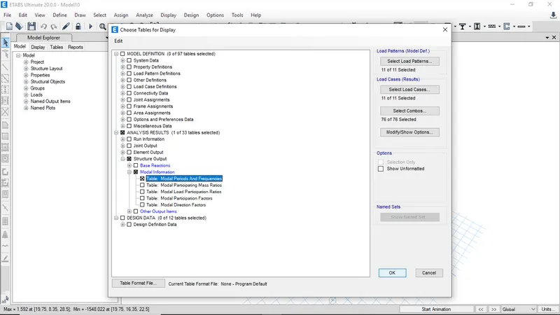
Select modal periods and frequencies to view results
-
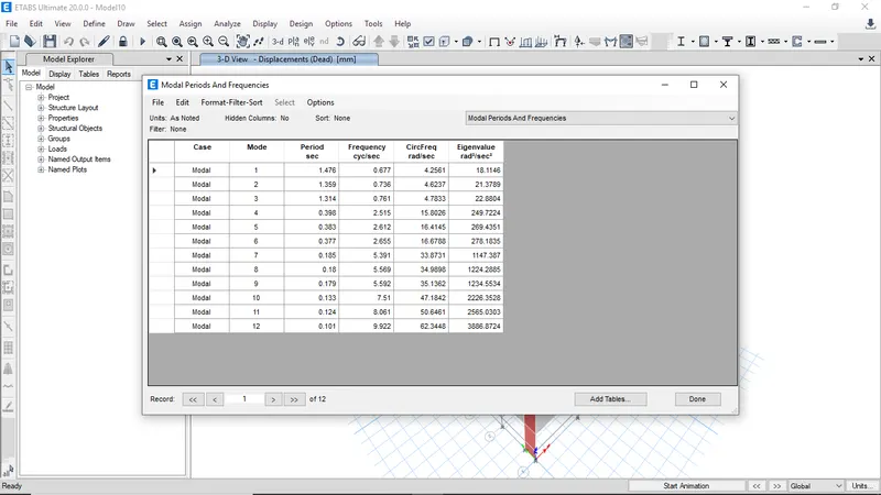
The below image shows modsl periods
-
The first mode has 1.47 sec
-
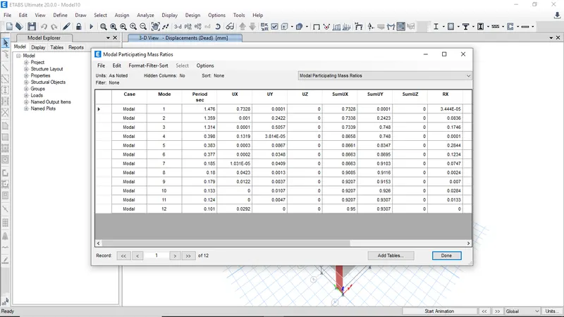
Now the Modal Participating Mass Ratios table will be visible, as shown below.
-
For this building the 2 mode is the torsion mode so it has some vertical irregularity
-
Need to improve stiffness in y direction
-
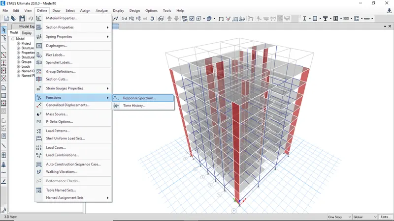
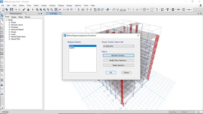
Now we select the Response spectrum from the Functions from define option, as shown below.
-
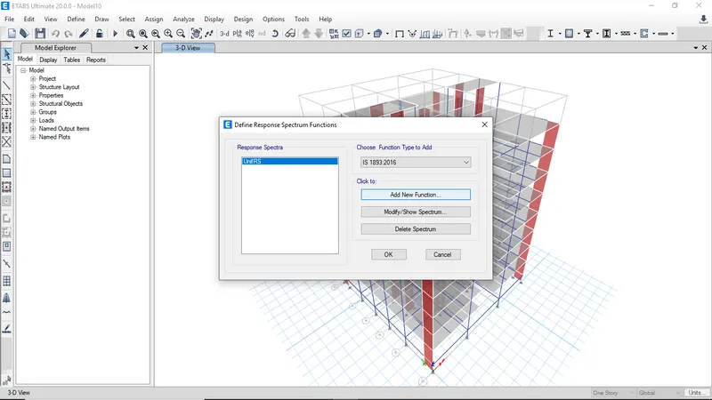
After selecting the Respnse spectrum the new tab is visible, In that choose IS 1893 2016 from dropdown and click on the Modify/Show spectrum option
-
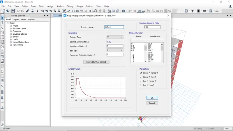
This will open window to edit the function
-
Give Function name as 'ISFun' and remaining details will be set by the software itself,we don't need to change any of the details in that response spectrum function tab
-
Click ok to finish
-
Click ok to finish and save function
-
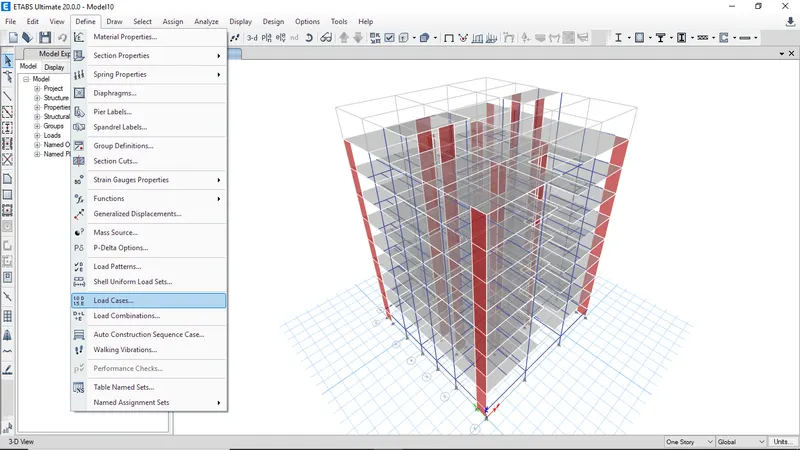
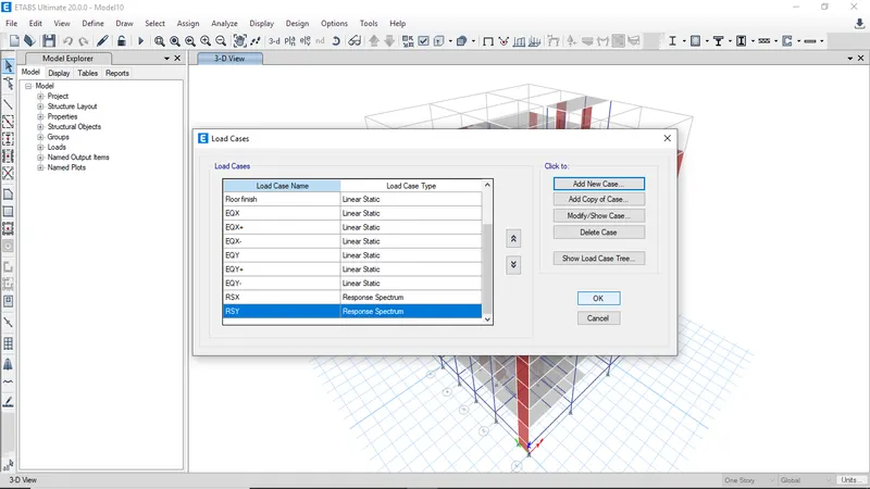
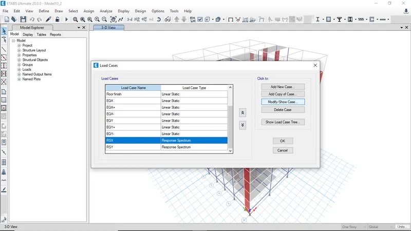
Now go to load cases to add response sepectum in X and Y direction
-
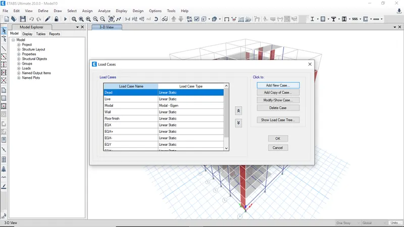
Click on add new case
-
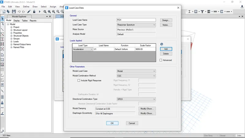
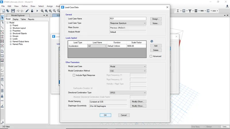
Enter the load case name as RSX and click on add and click ok to finish
-
Similar way create RSY and add the function
-
After creating the load cased click ok to finish
-
The again need to delete the old load combination and create the new load combo
-
Then add default load combo and click ok
-
The software will create default load combo and click ok
-
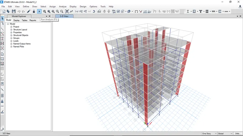
3d view of the final model
-
Click run analysis to analyse
-
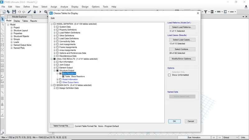
After analysis to click view tables option
-
Now we select the Base Reactions and click on the ok button, as shown below.
-
The base reactions are shown in below image
-
Here we have to check that EQ should be closer to the RSX, to get the closer to each other we should calculate the
Scale factor of Response spectrum. -
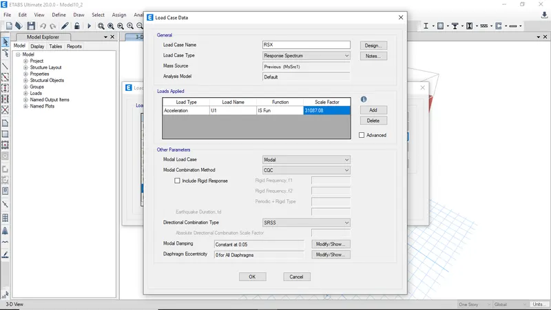
Calculate scale factor in X-direction `2958.06/931.75=3.17`
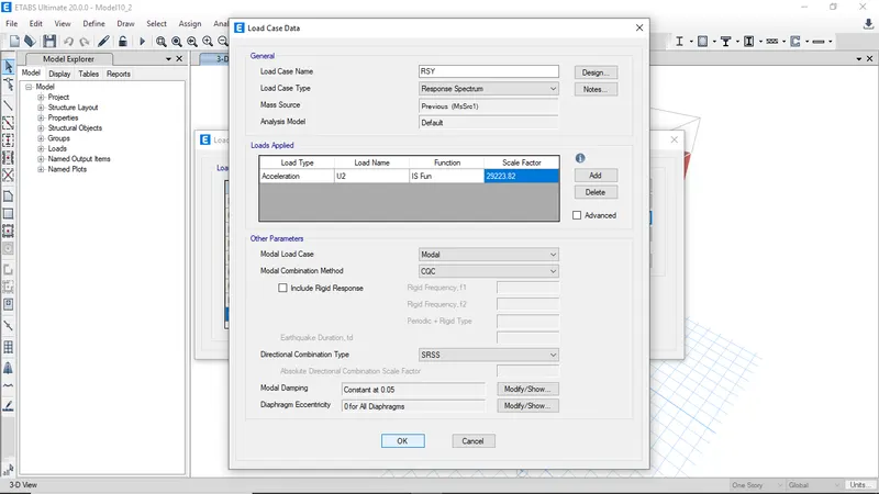
In Y-direction `2958.06/991.03=2.98`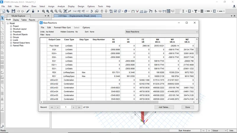
-
We need to add above values as scale factor for response spectrum at X and Y directions in the load case data.
-
Add the scale factor for both X and Y direction for response spectrum load case
-
After modifying click ok to finish
-
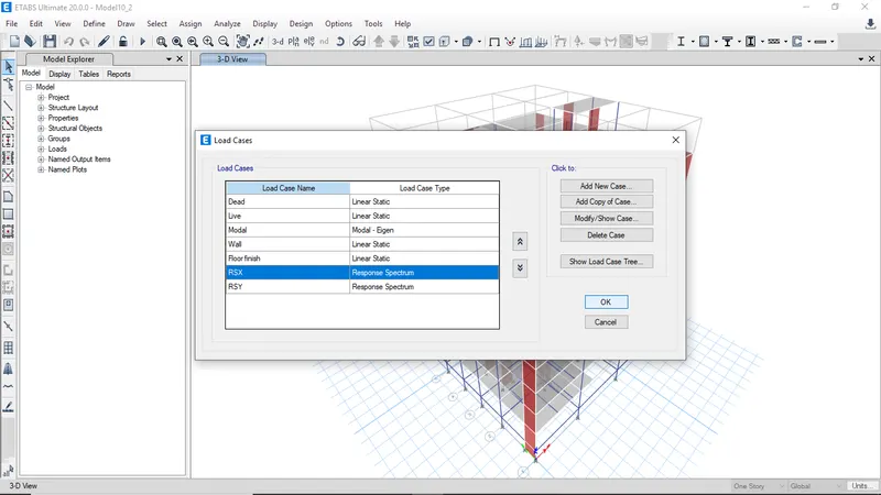
Detele the EQX and EQY loads case and save file as another for respnse spectrum analysis
-
Again genarate new load combo
-
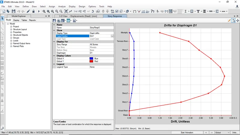
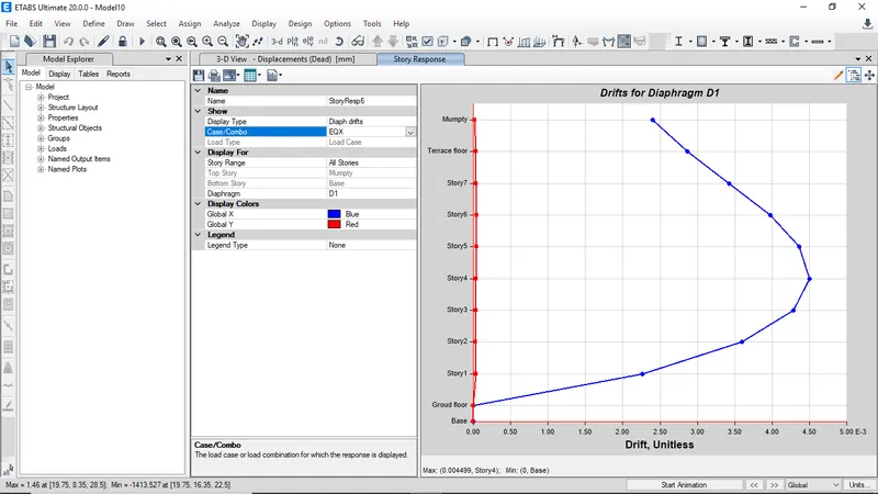
The story response for maximum story drifts at X directions, should not be more than 4%.
-
But it more in Y direction so increate stiffness in Y direction
-
Next switch to base plan view
-
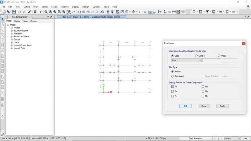
Next we have to open the reactions tab, then we select the eartquake load towards X-direction(EQX) in the load case, then click on the ok buttion
-
Now the base shear reactions will appear, as shown below.
When we divide the base shear taken up by the shear wall divided by the total base shear of building will get the % of the shear forces taken up by the shear wall.
And if that is less than 80%, then the more shear walls we need to add to the structure.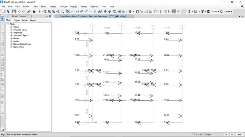
-
Also check for load combination
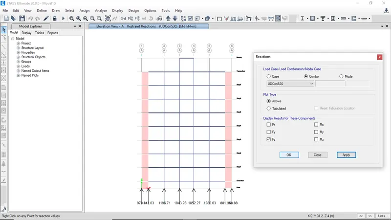
RESULTThe G+7 residential appartment building has been modelled and analyzed successfully using the ETABS 2020.
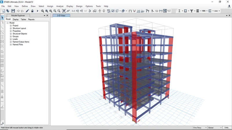
-
Columns, shear walls and beam are modeled and define each section property
-
Analysis is done for modal number, base shear storey drift aspect ratio, irregularity etc.,
-
As per the analyses result, building is bit flexible in y-axis, as shear wall are sufficient add additional column as provided in y-direction to meet the maximum storey drift limit.