Steady Vs Unsteady flow over a cylinder
1. The aim, Introduction, Theory:
The prim objective of present investigation is to numerically simulate the behaviour of fluid flow over a cylinder under two dimensional steady and unsteady state condition. The study of flow over a cylinder is one of the widely reported problem in the literature which is helpful in solving the aerodyanmic problems occuring in different application areas such as aerofoil design of an aeroplane, and automobile aerodynamics. in this present investigation a cylinder of diameter 2m subjected to flow of fluid having Reynolds number of 10,100,1000,10,000 and 100,000 is studied in dtail. During simulation under both steady and transient condition at the trailing edge of the cylinder vortex shedding formation takes place. The drag and lift coefficent were also computed fro various above listed Reynolds number. From the obtained results it is observed that the drag and lift are strongly depends on Reynolds number.
2. Solving & Modelling approach:
A two dimensional model for flow over a cylinder is created using ansys space claim. After constructing the geometry the meshing is carried out using triangular mesh structure with an element size of 2m, 1m, 0.5m and 0.25m. To catch the sharp gradient around the walls of cylinder the inflation layers are created in order to get a body fitted mesh. After running the solution for the mesh size of 2m the mesh reinement process is carried out until and unless a converged solution is obtained.
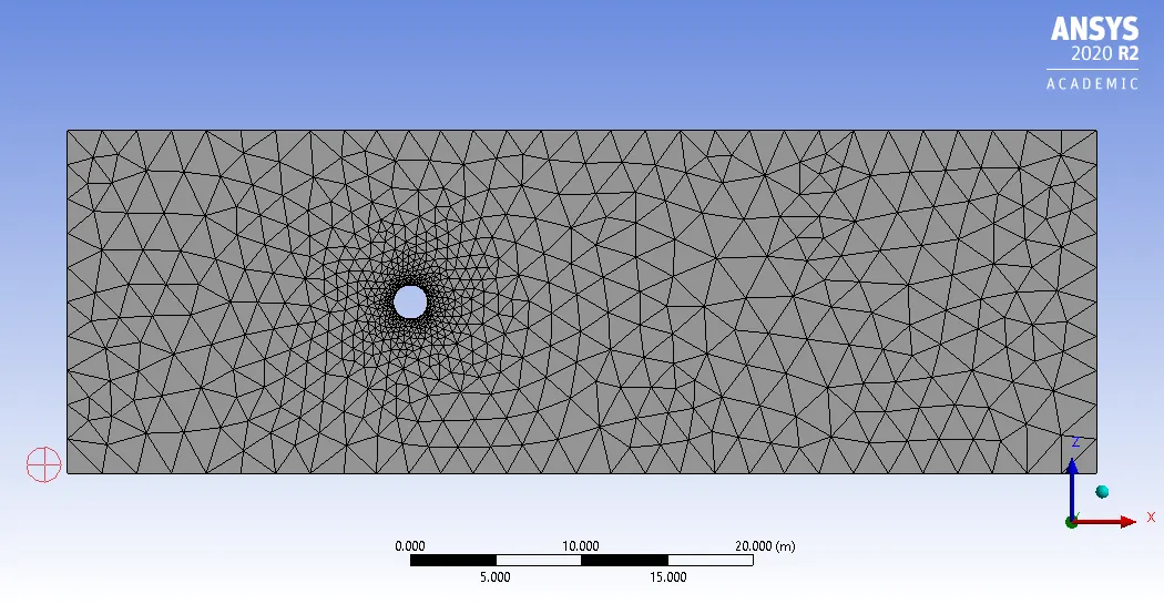
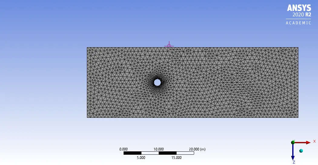
(a) No of elements=1648 , No of nodes=990 (b) No of elements=3368 , No of nodes=1890
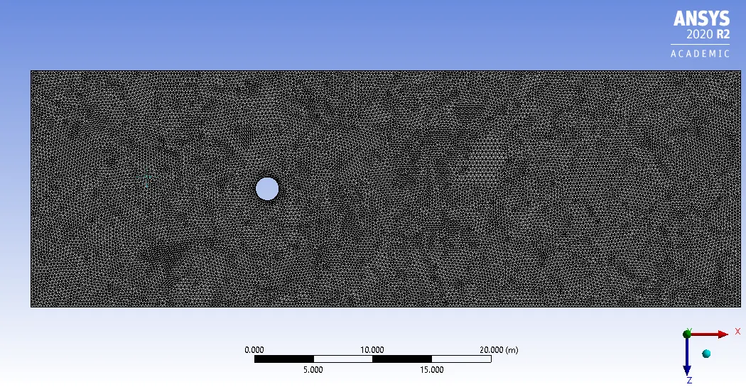
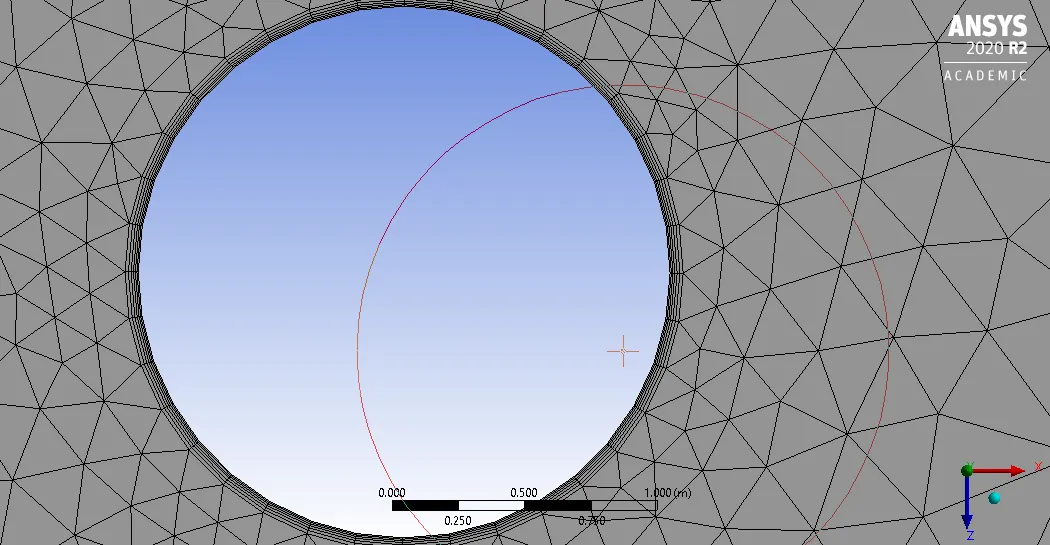
(c) No of elements=40502 , No of nodes= 20697 (d) Inflation layers
Figure 1. Mesh generation and refienement.
The solution initially run for all the above types of mesh sizes and for steady state analysis the number of iterations used vary from 300 to 500 and from the obtained residual plots of velocity the solution come to converge for mesh as shown in above figuure 1(c). The plots obtained for differetn number of iteration is shown in the figure 2 below.
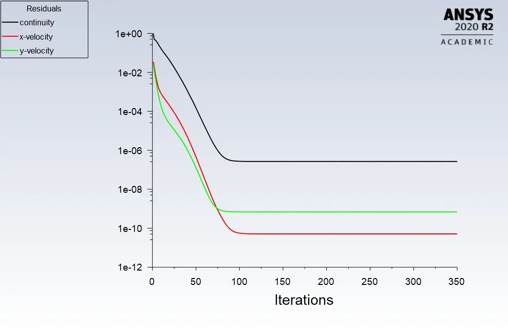
Figure 2 (a) Residual Plots for Re=100, iterations=350, Steady flow, No of elements=3368 , No of nodes=1890.
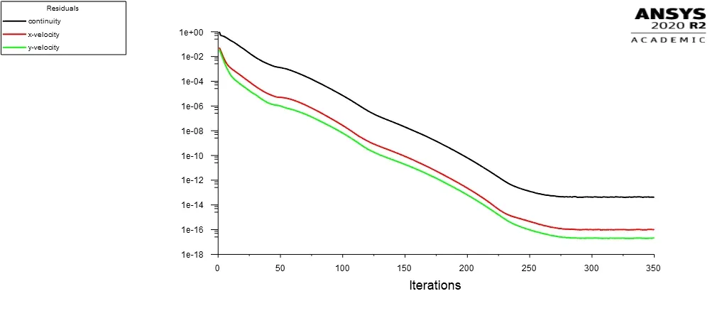
Figure 2 (b) Residual Plots for Re=100, iterations=350, Steady flow, No of elements=1648 , No of nodes=990
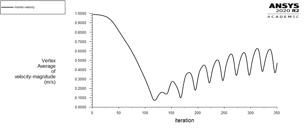
Figure 2(c) Monitor point velocity plot, Re=100, Steady flow, No of elements=40502 , No of nodes= 20697.

Figure 2 (d) Residual Plots for Re=100, iterations=450, Steady flow, No of elements=40502 , No of nodes= 20697.
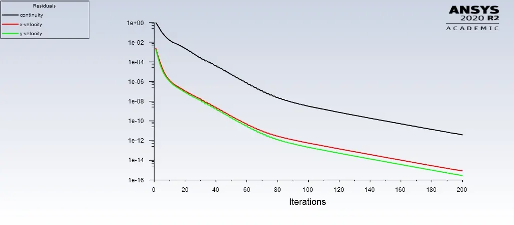
Figure 3 (a) Residual Plots Residual Plots for Re=100, transient, time steps=200, No of elements=40502 , No of nodes= 20697.
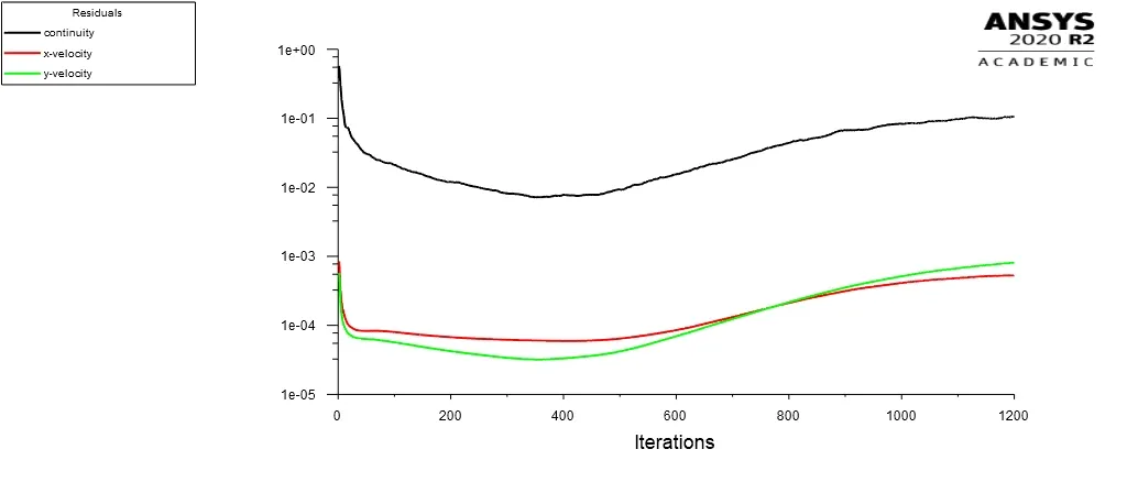
Figure 3 (b) Residual Plots Residual Plots for Re=100, transient, time steps=1200, No of elements=40502 , No of nodes= 20697.
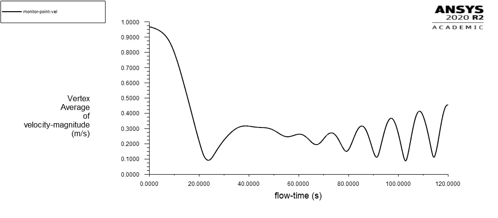
Figure 3(c) Monitor point velocity plots, Re=100, Transient flow, time steps=1200, No of elements=40502 , No of nodes= 20697.
Table1: Convergence criteria
| Sr No | Reynolds Number (Re) | Solver type | Mesh element size | No of nodes | No of elemenets | No of Iterations/ time steps |
| 1 | 100 | Steady | 2m | 990 | 1648 | 350 |
| 2 | 100 | Steady | 1m | 1890 | 3368 | 350 |
| 3 | 100 | steady /transient | 0.25m | 20697 | 40502 | 450/200/1200 |
The vortex shedding under steady state condition is observed for the mesh with element size of 0.25m and Reynolds number of 100 (Velocity =1m/s, density=1kg/m^3, viscosity= 0.02kg/m-s). By observing the residual plots we came to conclusion that the solution get converged sfter 250 itration for mesh element size of 0.25m under steady state condition. And for transient condition the solution gets converged after 1000 time steps. It is also observed from the monitor point velocity plot that the behaviour of vortex shedding behind the cylinder almost give the same characteristics.
3.Pre-processing and solver setting:
Part-I
A) Steady flow analysis:
The following fluid flow parameters are used for the analysis purpose
Inlet velocity of fluid=1m/s
Outlet pressure= 0 pascals
Daimeter of Cylinder=2m
Density=1kg/m^3
Viscosity= 0.02 Kg/m-s
Solver: Steady state, pressure based solver
Method: SIMPLE
B) Transeint flow analysis:
The following fluid flow parameters are used for the analysis purpose
Inlet velocity of fluid=1m/s
Outlet pressure= 0 pascals
Daimeter of Cylinder=2m
Density=1kg/m^3
Viscosity= 0.02 Kg/m-s
Solver: Transient state, pressure based solver
Method: COUPLED scheme
4. Results:
Part-1
Vortex shedding behind the cylinder:
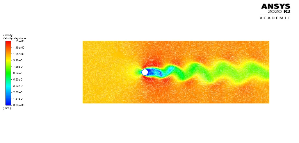
Figure 4 (a) Vortex Shedding, Re=100, Steady flow, No of iterations=350
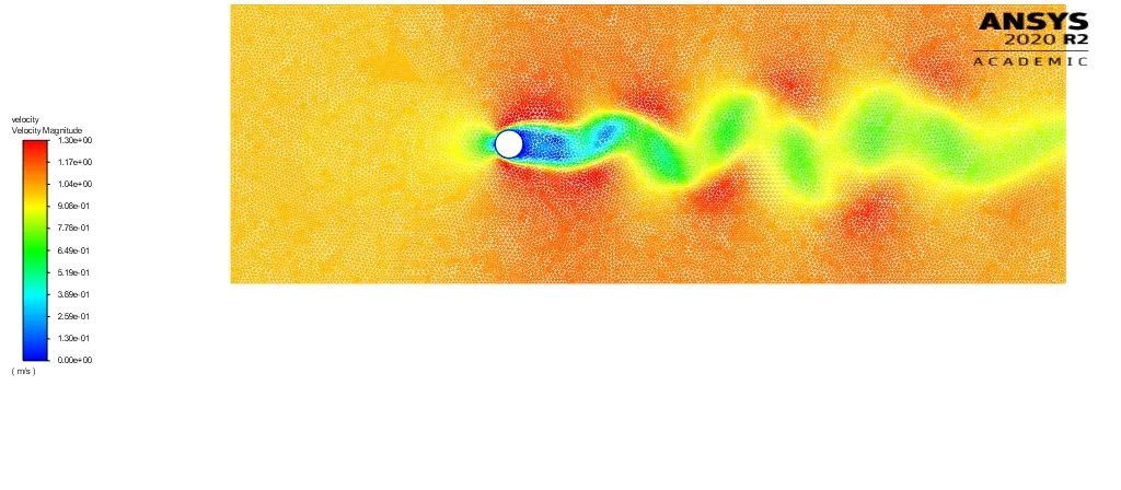
Figure 4 (b) Vortex Shedding, Re=100, Transient flow, Time steps=1200.
By manual calculation using strouhal number formula
Steady flow:
Sr= fd/v
Where f= frequency of oscillations per unit time.
d= diameter of the cylinder.
v= velocity of flow in m/s
Sr=0.15 (Re=100) for steady flow condition.
Sr= 0.13 (Re=100) for transient flow condition.
PART-II
- Calculate the coefficient of drag and lift over a cylinder by setting the Reynolds number to 10,100,1000,10000 & 100000. (Run with steady solver)
- Discuss the effect of Reynolds number on the coefficient of drag. [ Results should be validated with any standard literature and error should be within 5 %]
1. Coefficient of drag and Lift plots.
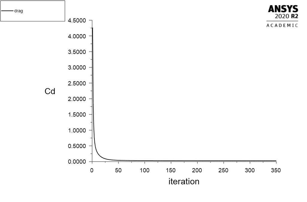
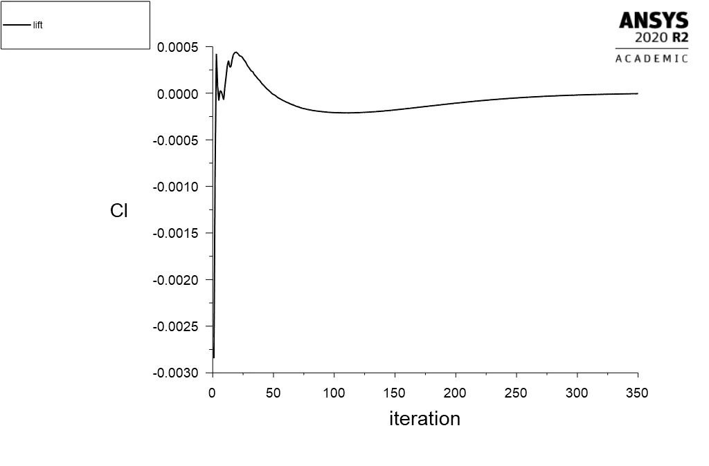
Figure 5. Drag and Lift coefficients, Re=10, Steady solver (Velocity=0.1m/s)
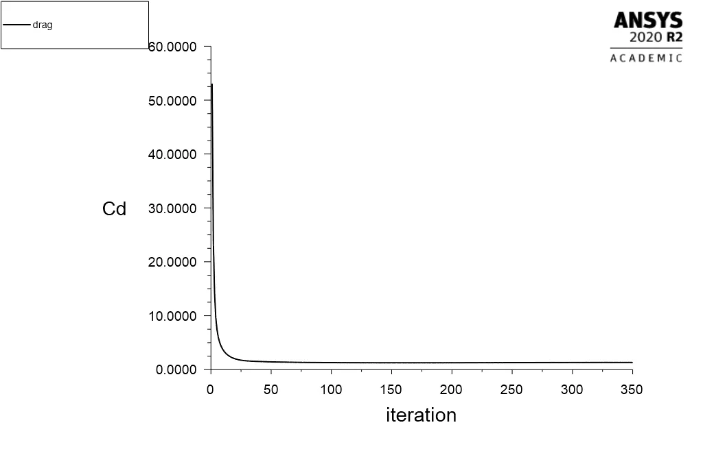
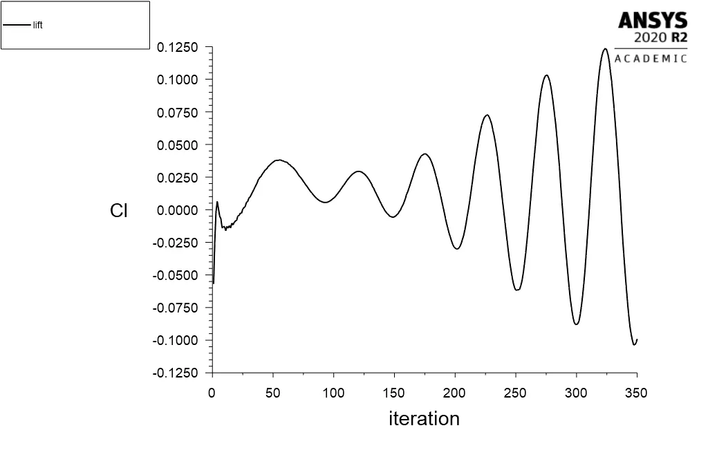
Figure 6. Lift and drag coefficient plots alongwith vortex shedding Re=100, Steady Solver (Velocity=1m/s).
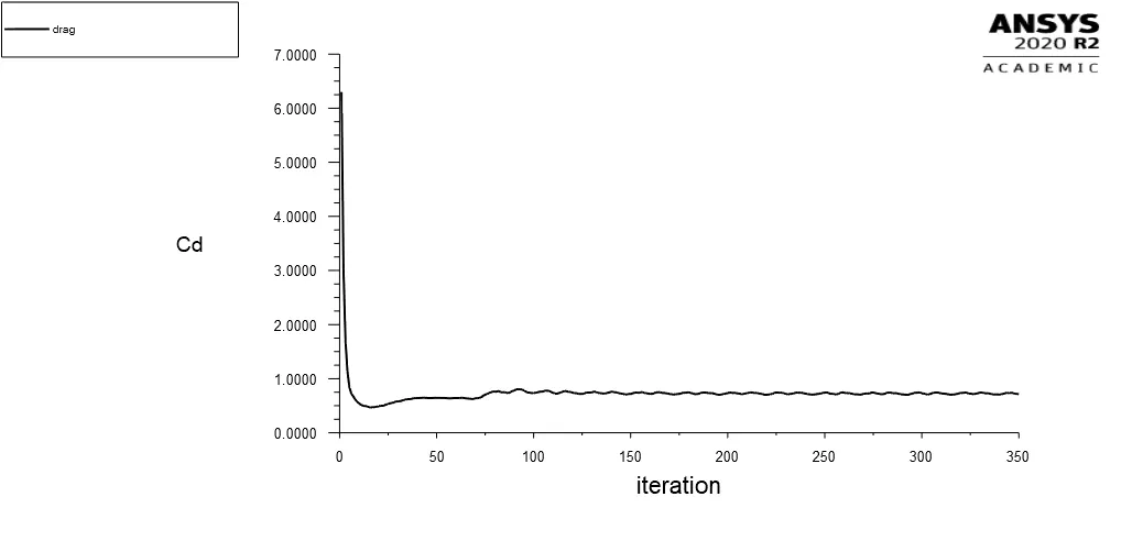
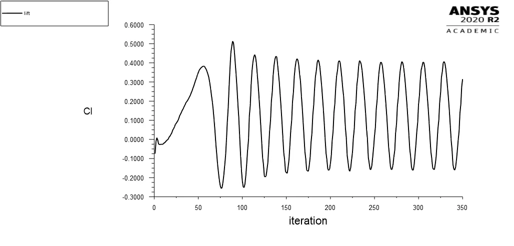
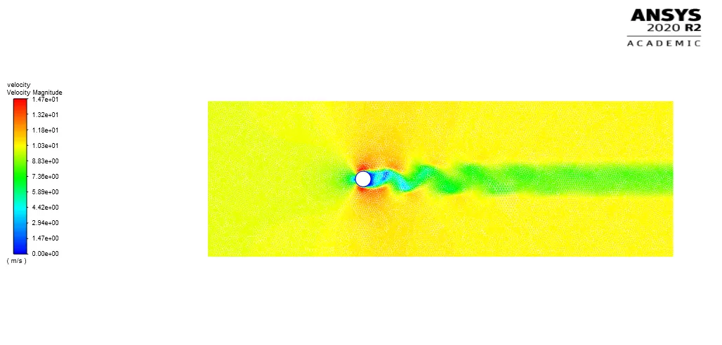
Figure 7. Lift and drag coefficient plots alongwith vortex shedding Re=1000, Steady Solver (Velocity=10m/s).
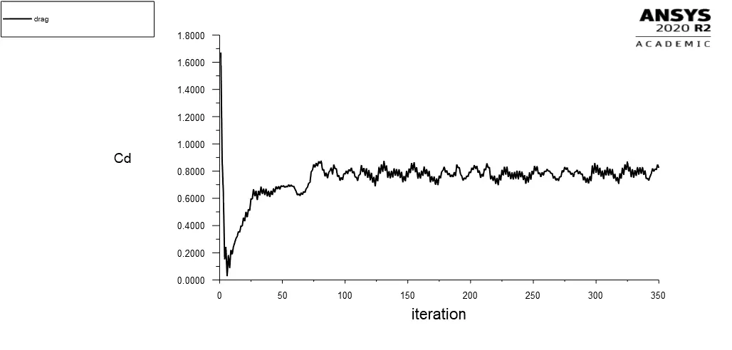
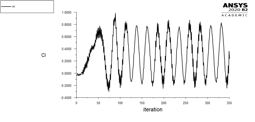
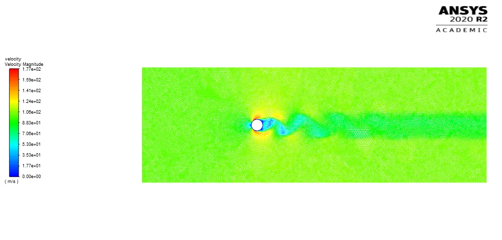
Figure 8. Lift and drag coefficient plots alongwith vortex shedding Re=10,000, Steady Solver (Velocity=100m/s).
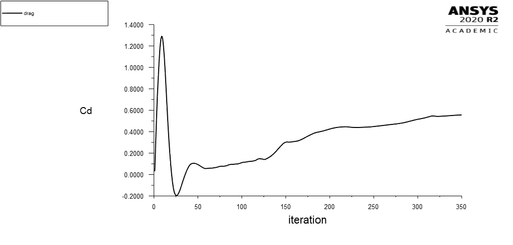
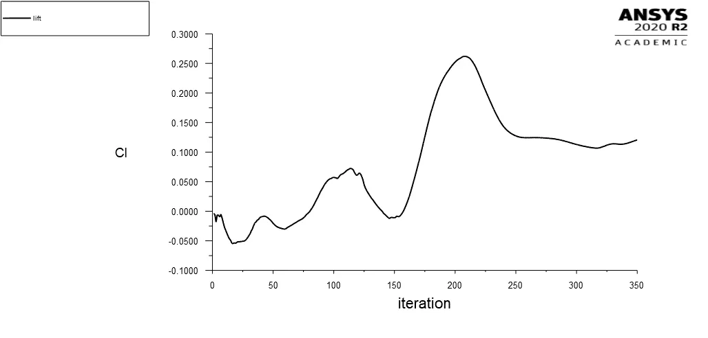
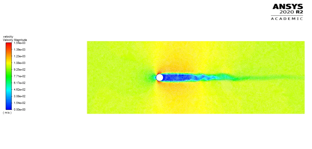
Figure 9. Lift and drag coefficient plots alongwith vortex shedding Re=10,000, Steady, density based Solver (Velocity=1000m/s).
From the above listed figures for drag coefficient it is observed that with change in the Reynolds number the drag coeffciecnt also changes and with increase in the Reynolds number the drag coefficient on the cylinder wall decreases.
Table 3. Drag and Lift coefficient
| Sr No | Re | Velocity (m/s) | CL(Lift) | CD (Drag) |
| 1 | 10 | 0.1 | 0.0001 | 000 |
| 2 | 100 | 1 | 0.025 | 1.25 |
| 3 | 1000 | 10 | 0.2 | 0.65 |
| 4 | 10000 | 100 | 0.2 | 0.55 |
| 5 | 100000 | 1000 | 0.14 | 0.49 |
5. Conclusion:
I. Under laminar flow regime the vortex shedding occurs behindthe cylinder when Reynolds number reaches a value of 100 in both the cases of steady and transient flow condition.
II. It is difficult to get the vortex shedding under steady state laminar flow regime at low Reynolds number of 40 and less.
III. The lift coefficient increases with increase in the Reynolds number.
IV. The drag coefficient decreases with increase in the Reynolds number.
V. With increase in the Reynolds number the vortex shaedding behind the cylinder disappears.
References:
1. B.N Rajani, A. Kandasamy, Sekhar Majumdar, " Numerical simulation of laminar flow past a circular cylinder"Applied Mathematical Modelling, Volume 33, Issue 3, March 2009, Pages 1228- 1247.