Conjugate Heat Transfer Analysis on a graphics card.
1. The aim, Introduction, Theory:
The prime objective of this challenge is to perform a conjugate heat transfer analysis of Graphics card model subjected to flow of air under stedy state condition using Ansys fluent 2020R2. Three different air velocities (2m/s, 3.5m/s and 5m/s) are selected for thr CHT analysis.
A graphics card is a computer hardware device which is generally used to render the colourful image to monitor. It basically consist of three majore parts, the base PCB body, Processor, and Fins body. A processor is the heat source term generating a volumetric heat of aroung 1e^8 W/m^3. In order to achieve efficient and good performance of Graphics card it is necessary to remove the amount of heat generated within it so as to maintain its temperature within the permissible value.
As the process of heating and cooling involves the interaction between hot graphics card and flowing air over it due to fluid solid intraction the amount of heat transfered from the solid graphics card to the fluid air occurs under conjugate (Continuity of temperature and heat flux at solid fluid interface) heat transfer condition.
2. Solving & Modelling approach:
The processor part of the graphics card generate very large amount of heat which is transfered to base body and fins body by conduction and air flowing over the graphics card takes away the heat by convection mode.
After importing the geometry to space claim use the share topology commond and share commond in order to get the conformal mesh during meshing operation.
After this open the meshing window and generate the mesh with default mesh setting this will give a coarse mesh.
For generating the refined mesh use the following parameters in mesh details
Enclosure: use sizing option and change the element size to 3mm
Base PCB Body: Use body sizing option and set element size to 1mm
Fins body : Use body sizing option and set element size as 1mm
Processor:Use body sizing option and set element size as 0.5mm
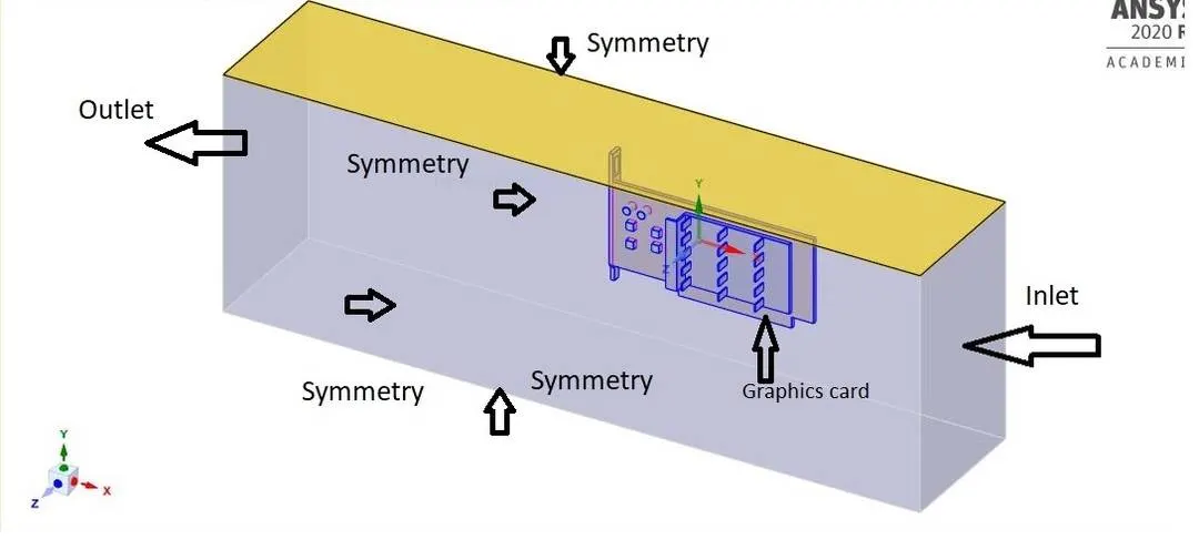
Figure1. Graphics card and enclosure geometry.
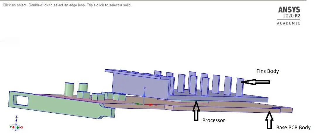
Figure2. Parts of Graphics card.
Table1. Details of Material Used.
| Sl No | Domain | Material | Density (Kg/m^3) | Thermal Conductivity(W/mK) | Specific Heat(J/KgK) |
| 1 | Fluid | Air | 1.225 | 0.0242 | 1006.43 |
| 2 | Solid (Base body) | Aluminium | 2719 | 202.4 | 871 |
| Solid (Processor) | Silicon | 2000 | 150 | 710 | |
| Solid (Fins body) | Copper | 8978 | 387.6 | 381 |
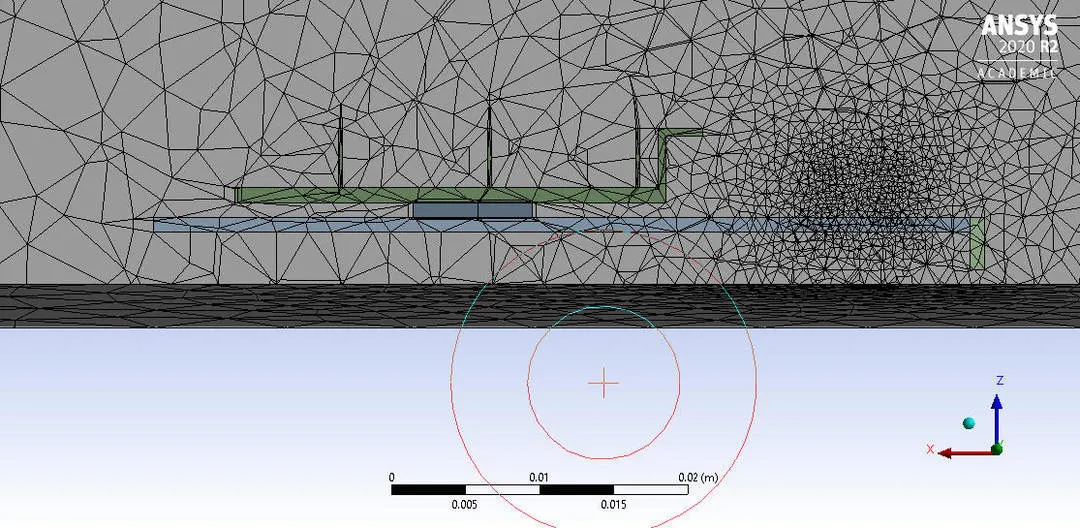
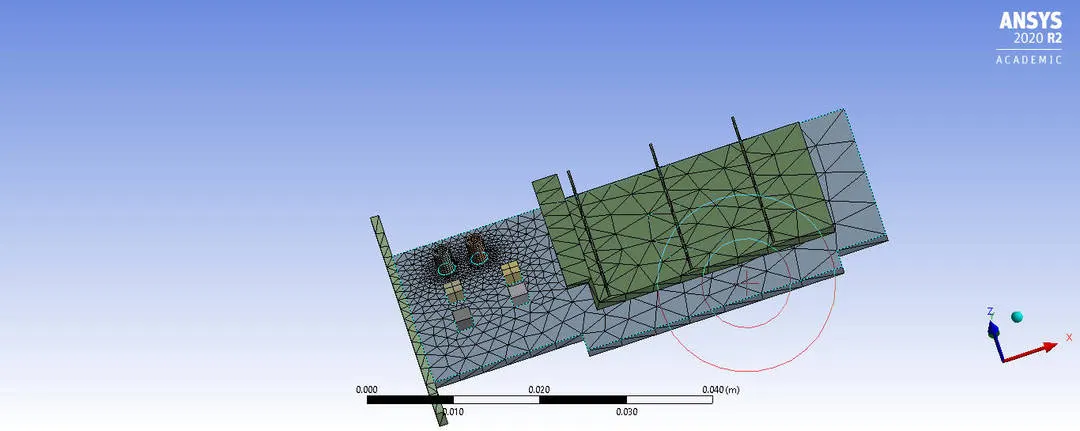
Figure 3 . Case-1 : Coarse Mesh
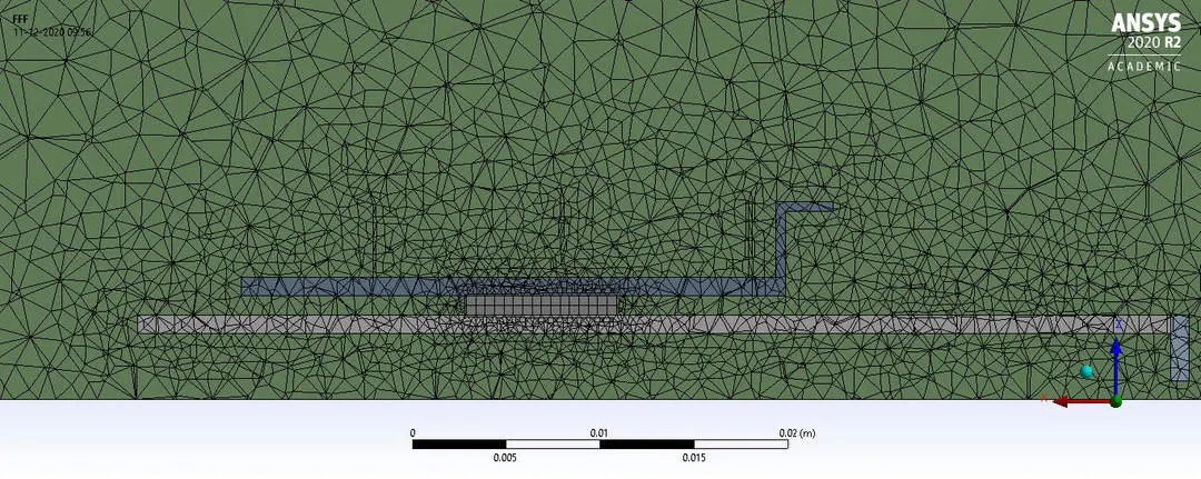
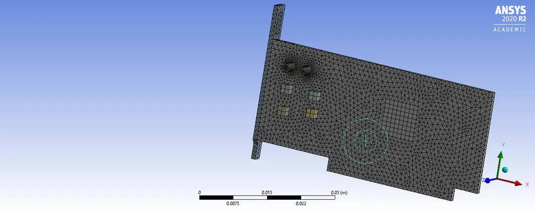
(a) Sectional view of refined mesh. (b) Base body
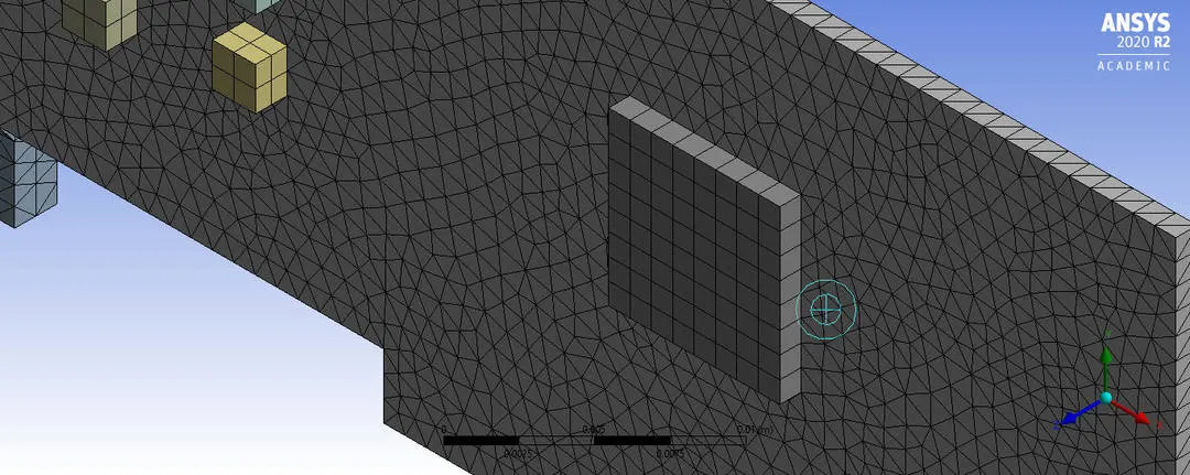
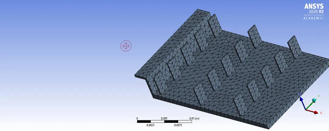
(c) Processor (d) Fin Body
Figure 4(a). Case-2 Refined Mesh.
| Sl No | Mesh Type | Number of nodes | Number of Elements |
| Case-1 | Coarse Mesh | 18699 | 97812 |
| Case-2 | Refined Mesh | 70634 | 398548 |
3. Pre-processing and solver setting:
Preprocessing: After generating the mesh next the geometry is opened with set up window and the following parameters are used.
Solver Setting:
The following set up is used for this challenge
Solver: Pressure based, Steady State.
Model: Viscou, K-epsilon standard model.
Method: Coupled Scheme with second order upwind
Physics:
Material used
Outer Enclosure: Air (Fluid domain)
Processor: Silicon (Solid)
Fins Body: Copper (Solid)
Base Body: Aluminium (Solid)
Boundary Conditions:
Inlet: velocity, 2m/s, 3.5m/s, and 5m/s, Temperature=300K
Outlet: Pressure: Gauge pressure.
Enclosure : Symmetry
Source Term=1, Heat generation rate=1e^8 W/m^3 (Processor is generating the volumetric heat)
Initilization: Standard method

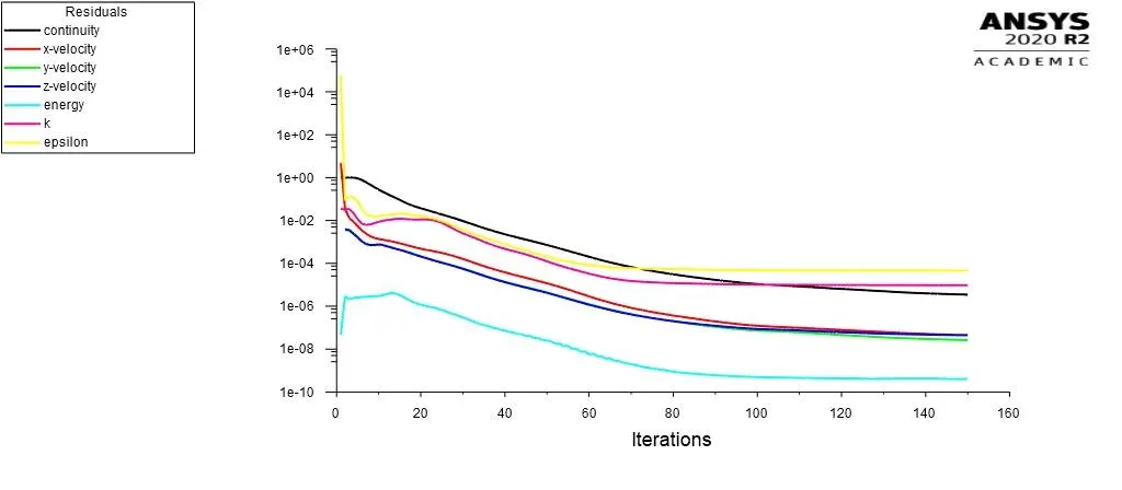
Figure 4 (b). Convergence achieved after 120 iterations.
(a)
(b)
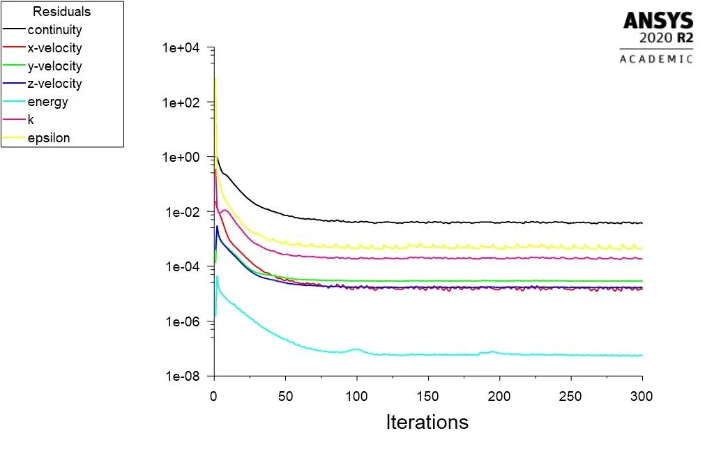
Figure 5. Residual Plots (a) Case-1 (b) Case-2
With above set up the solution is initilised by standard method while the number of iterations used for coarse mesh are 300 and for refined mesh the number of iterations are 150. It can be clearly observed from the residual plots obtained the convergence is reached around 120 iterations.
4. Results:
(a) (b)
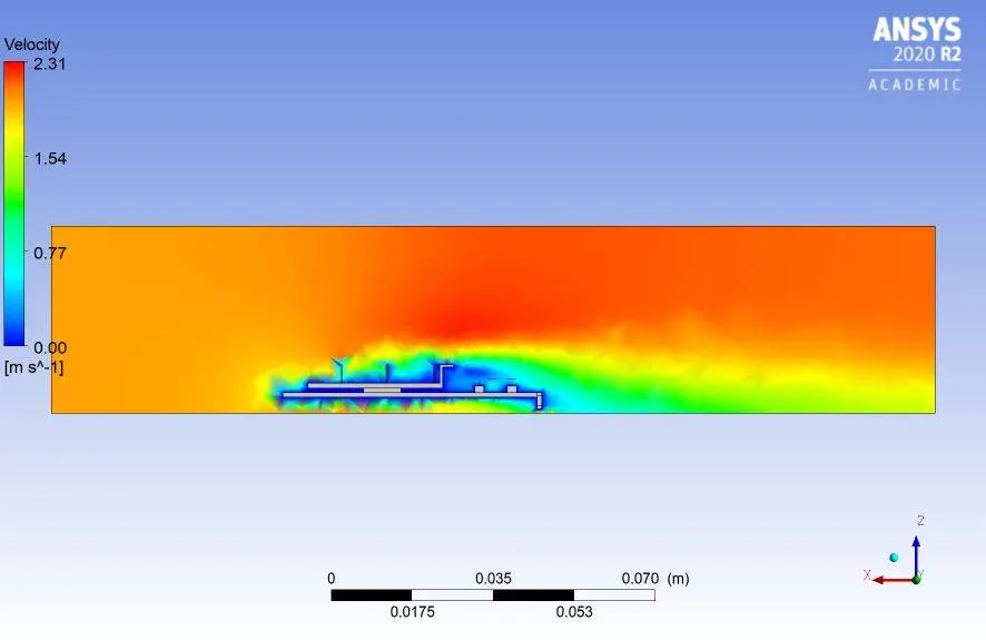
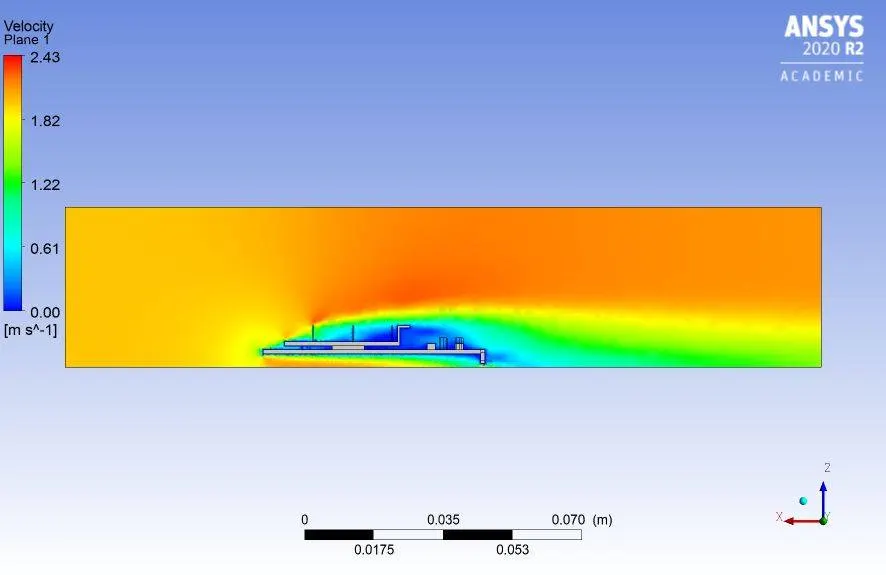
Figure 6. Velocity contours (a) Case-1 (b) Case-2 for inlet velocity of 2m/s.
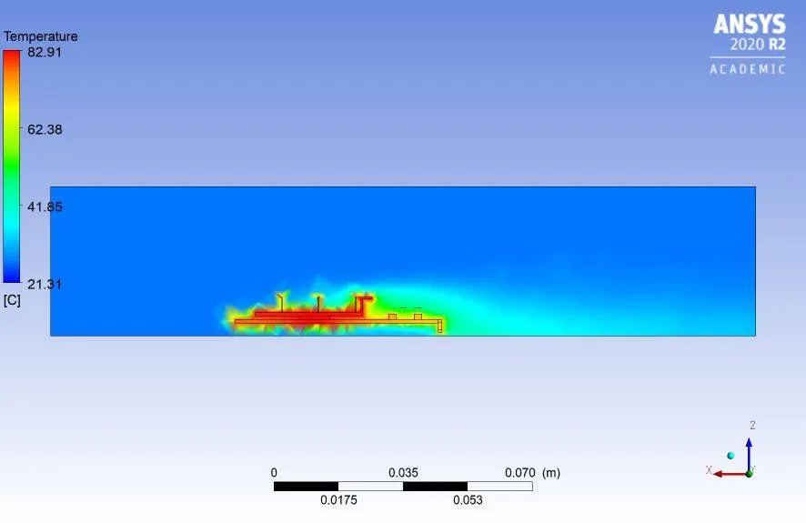
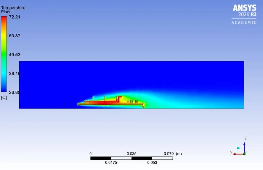
Figure 7. Temperature contours (a) Case-1 (b) Case-2 for inlet velocity 2m/s
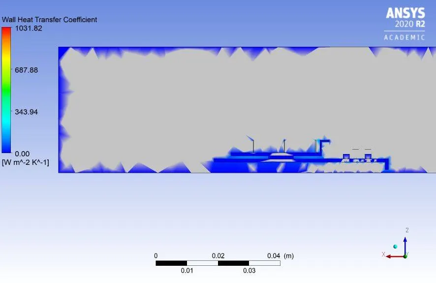
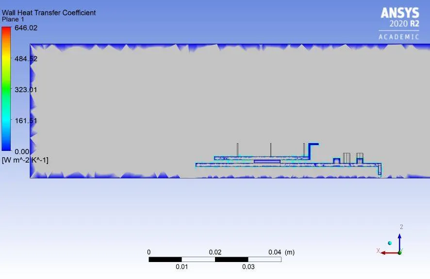
(a) (b)
Figure 8. Wall Heat Transfer Coefficient (a) Case-1 (b) Case-2 for inlet velocity=2m/s
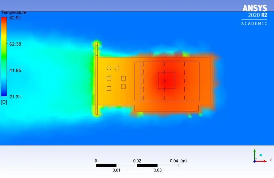
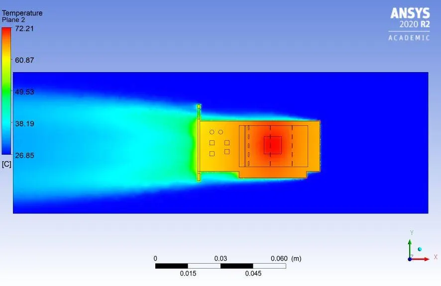
(a) (b)
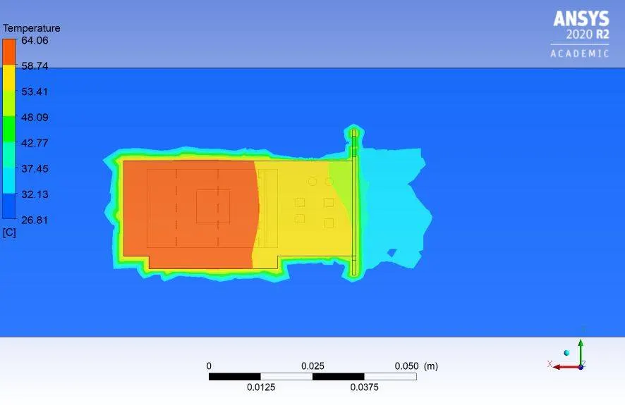
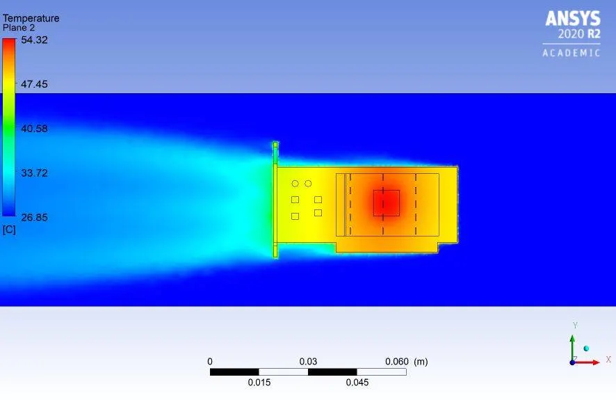
Figure 9. Hot spot regions on model (a)Case-1 (b) Case-2
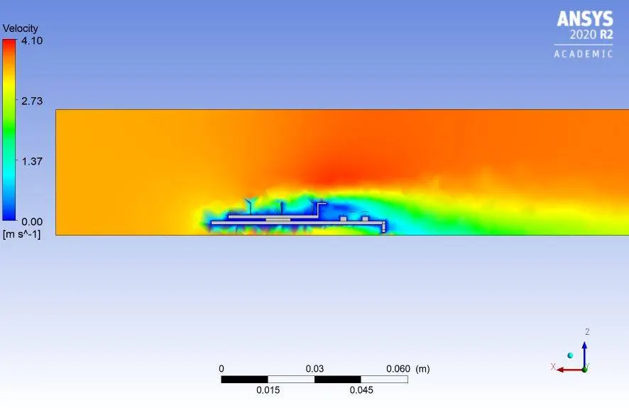
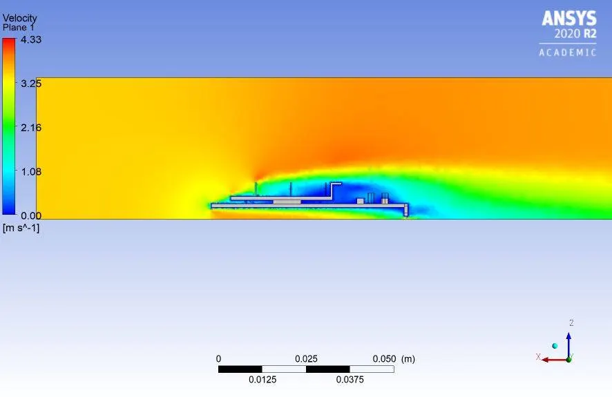
(a) (b)
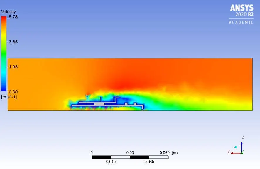
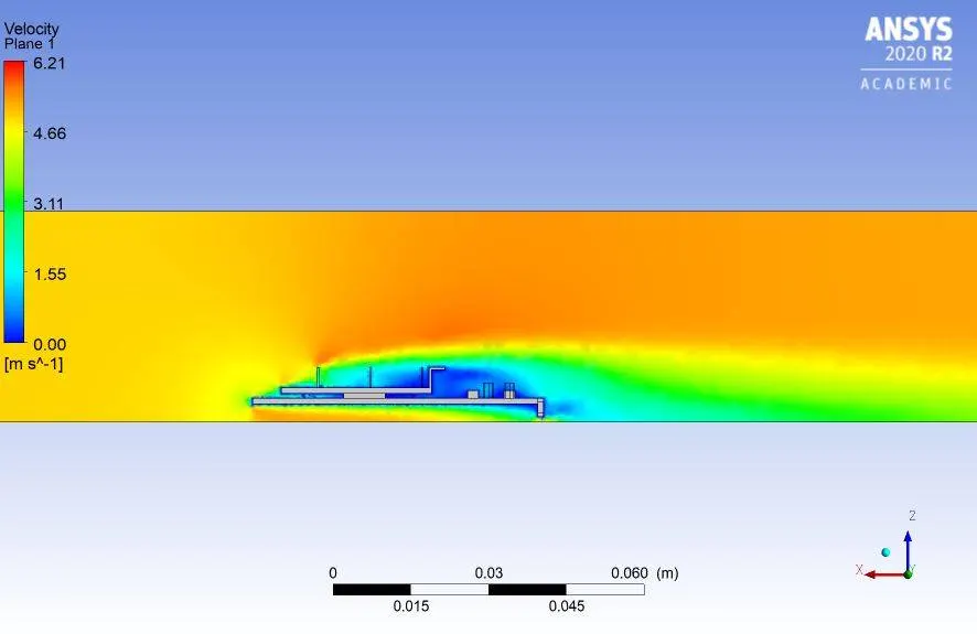
Figure 10. Velocity Contours (a) Case-1 (b) Case-2 for velocity 3.5m/s.
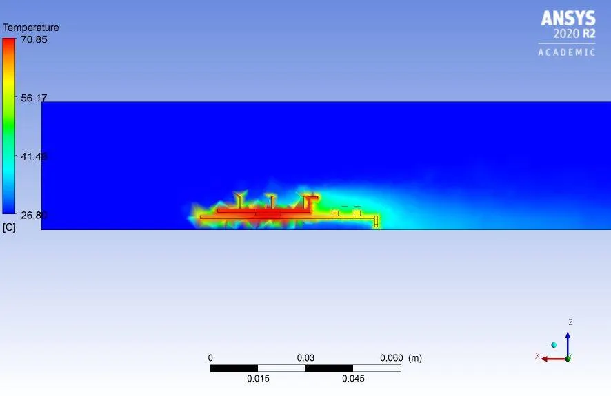
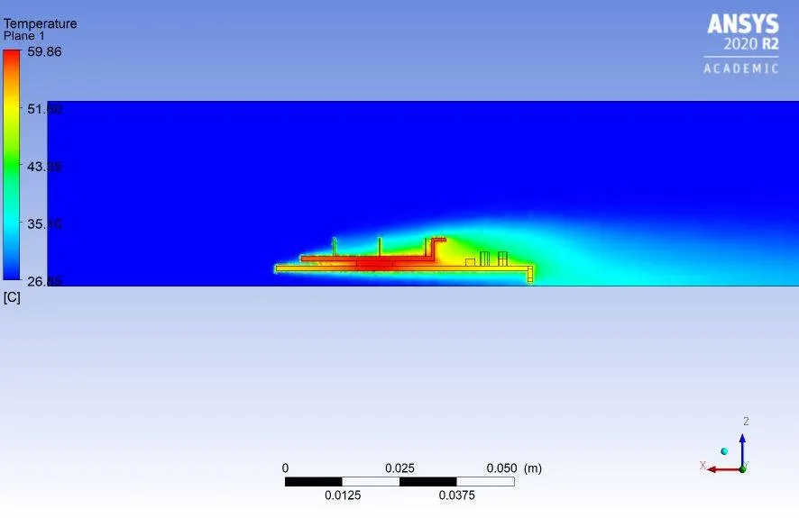
(a) (b)
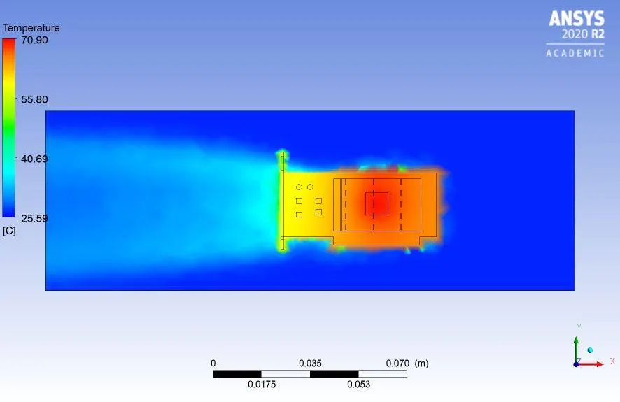
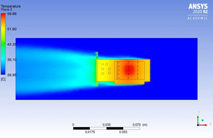
Figure 11. Temperature contours (a) Case-1 (b) Case-2 for velocity 3.5m/s.
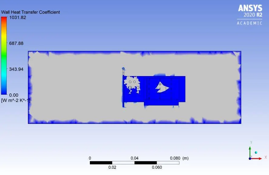
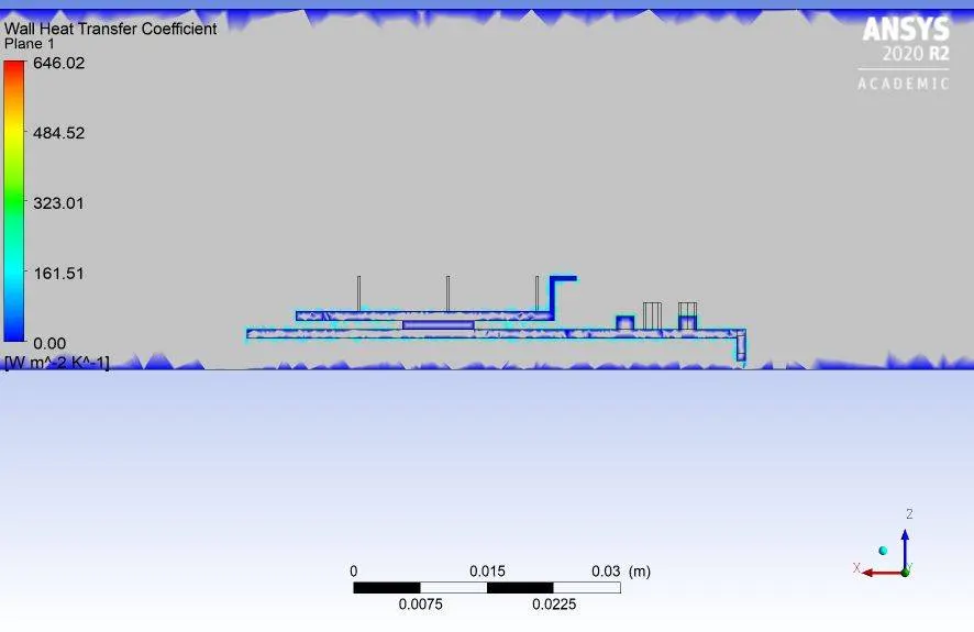
(a) (b)
Figure 12. Wall Heat transfer coefficient (a) Case-1 (b) Case-2 for velocity 3.5m/s.
(a)
 (b)
(b)
Figure 13. Hot spot regions on model(a) Case-1 (b) Case-2 for velocity 3.5m/s.
(a) (b)
Figure 14. Velocity contours (a) Case-1 (b) Case-2 for velocity 5m/s.
(a) (b)
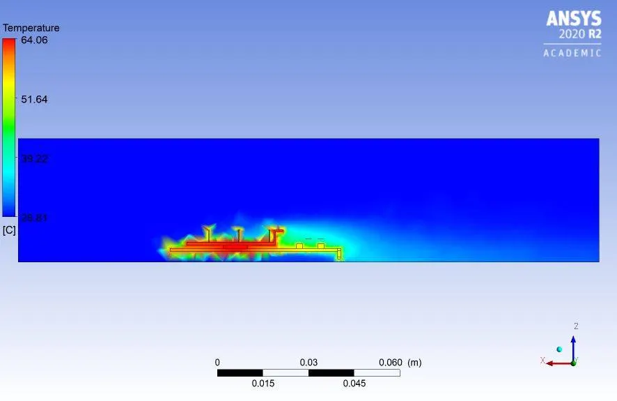
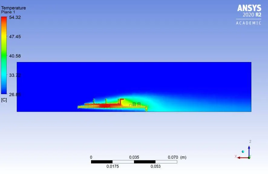
Figure 15. Temperature contours (a) Case-1 (b) Case-2 for velocity 5m/s.
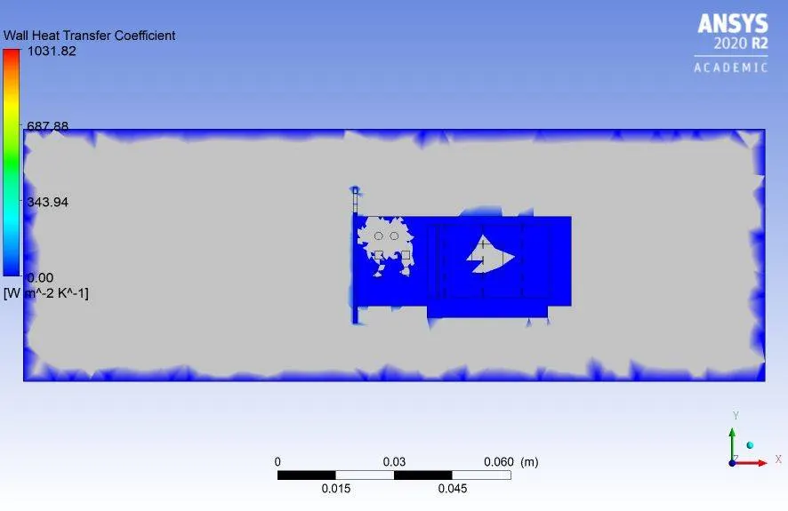
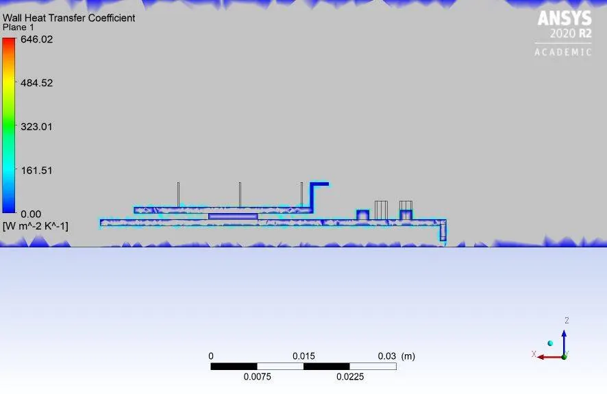
(a) (b)
Figure 16. Wall Heat Transfer Coefficient (a) Case-1 (b) Case-2 for velocity 5m/s.
(a) (b)
Figure 17. Hot spot regions on model (a) Case-1 (b) Case-2 for velocity 5m/s.
5. Conclusion:
The following conclusions can be made from the above obtained results.
- The coarse mesh gives vague results compare to refined mesh.
- The solution reach converegence after 120 number of iterations.
- It is observed that for both the cases anlayzed in the present challenge with increase in the velocity of air the temperature in graphics card decreases.
- A 10 degree celsius temperature difference is obtained for refined case as compare to coarse mesh for same velocity.
- The temperature range in the graphics card is better controlled by high velocity but at the expense of more pumping power.
- The maximum temperature is seen in case of coarse mesh with velocity of 2m/s.
- The minimum temperature is obtained in case of refined mesh with velocity of 5m/s.
- The maximum temperature noted for the coarse mesh is around 83 degree celsius for air velocity of 2m/s.
- The maximum temperature is around 72 degree celsius for the refined mesh case for the air velocity of 2m/s
- The region occupied by hot spot in case of refined mesh is less as compared to coarse mesh for velocity of 5m/s.
- It is better to use refined mesh with velocity of 5m/s in order to maintain the processor surface temperature at minimum level.
- The temperature distribution is more uniform in case of refined mesh compare to coarse mesh for all the ranges of velocity.
- The potential hot spots were observed near the processor ,fins and base body.