Ahmed Body Challenge
1. The aim, Introduction, Theory:
Aerodynamic shape of any vehicle plays a very vital role in defining its effieiceincy in terms of fuel and power. Hence in order to achieve higher fuel efficiency in vehicle design various study have been performed considering different operating conditions and among these studies one of the most famous and highly accepted study was the bench mark problem related to aerodynamic analysis of Ahmed Body. The present numerical simulation is performed on Ahmed body subjected to flow of Air moving with a velocity of 25m/s. The study is performed in order to determine the drag and lift coefficients. Velocity and pressure contours along with Drag and Lift coefficient plots were illustrated in details.
- Ahmed Body and Its Importance:
Ahmed body is considered as a standard tool to study the other aerodaynamic vehicles.
S.R. Ahmed in the year 1984 was the person who experimenatlly depicted the analysis of Ahmed body. The simple shape of Ahmed body is having a length of 1.044m, width of 0.389m and height of 0.288m. It also consist of four projected cylindrical parts of height 0.5m each. The rear end of the Ahmed body has got a slant surface which is having an inclination of 40 degree.
Ahmed body plays a very vital role in defining the geometry and aerodynamic shape of the car and also plays an important role in computing the drag and lift coefficient on a body.
2. Solving & Modelling approach:
Basically the geometry of Ahmed body was constructed in Space Claim Ansys workbench according to its shape and dimensions. After refiening the geometry for simulation purpose and to reduce the computational time the Ahmed body is splitted in to two parts which are exactly mirror image to each other i.e. a line of symmetry exists at the center of the Ahmed body.In order to place the constructed Ahmed body in fluid domain an enclosure is constructed which will take care of inflow and outflow conditions. As the steep velocity gradients near the Ahmed body are formed in order to catch these gradients another small enclosure region is constructed in order to identify the variations near the wall of Ahmed Body.
The 3-D simulation of Ahmed body is carried out by using Ansys Fluent 2020 (R2). The inlet velocity considered for the analysis purpose is 25m/s. The influence of slant rear surface of Ahmed body on the wake region under given Reynolds number is simulated. The Coefficeint of Drag and lift are also computed and plotted for the rfernce purpose.
Initially the solution for the base line set up using default and coarse mesh is determined after observing the results of base line set up the mesh is refiend to fine size in order to catch and have a converged solution for the given conditions.
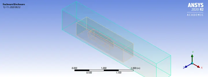
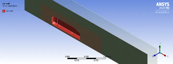
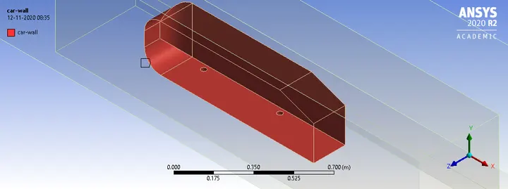
Fifure. Modelling of Ahmed Body
3. Pre-processing and solver setting:
Ahmed body geometry is a simple rectangular box with some features like slant face at the rear end and curved surface at the frontal area. The body is supported on projected cylinders.
Meshing: Two different types of meshing models were used
A. Base line Mesh:
A regular teterahedral mesh is generated over the Ahmed body and enclosure consisting of fluid domain. The solution is obtained by using following set up
Steady state.
Pressure based solver.
SIMPLE Algorithm.
K-epsilon turbulent model.
Inlet velocity=25m/s
Outlet pressure= Atmospheric pressure
Solution is Run for different number of iterations to catch the wake region and to achieve the convereged solution.
Figure 1 below reperesent the base line mesh
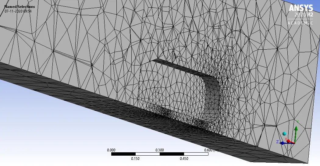
Figure 1. Base line mesh sectional view
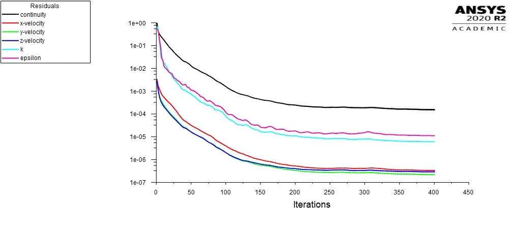
Figure 2. Residual Plot for base line set up.
As from the above figure 2 it is observed that for the base line mesh set up of Ahmed body the solution seems to be convereged after 250 iterations.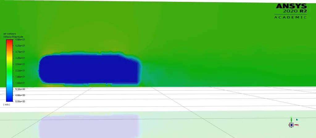
Figure 3. Velocity contours around Ahmed Body for Base line set up.
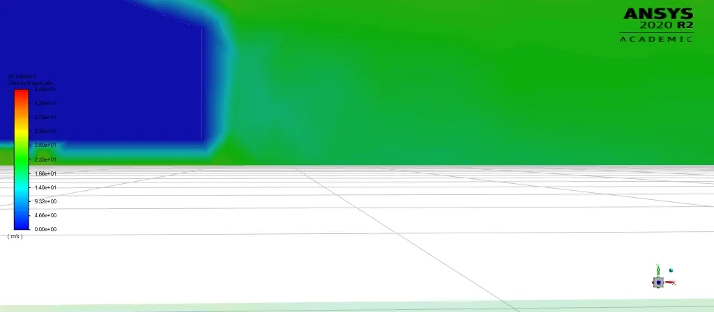
Figure 4. Wake region behind the Ahmed Body.
From above figure 3 and 4 it can be clearly said the obtained velocity contour and wake region are not clearly visible and the behaviour is also not satisfactory. Hence to catch velocity, pressure and wake region it is mandatory to refine the mesh near the Ahmed body. Hence it can be said that base line mesh is not sufficient to define the aerodynamic behaviour of Ahmed Body. Hence a better well refined mesh is needed.
B. Refined Mesh Set up:
In order to capture the velocity, pressure contours along with wake region behind the Ahmed body a well refined mesh has to be generated which will be helpful in defining the aerodynamic behaviour of Ahmed Body.
In order to have refined mesh a small enclosure is created near the ahmed body. And according to requirment the element size, inflation layer thickness (Y+) is added.
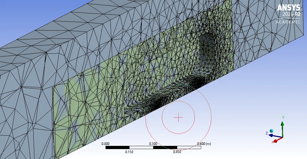
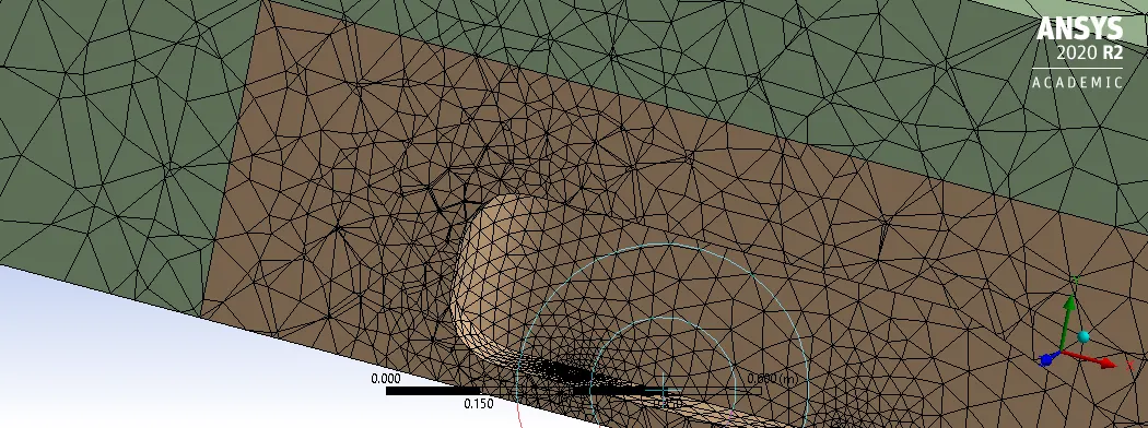
(a) Mesh Overlapping between Large and Small Enlosure.
(b) Overlapping Solved.
To solve overlapping problem of mesh use the Share topology option and in geometry use the interference tool.
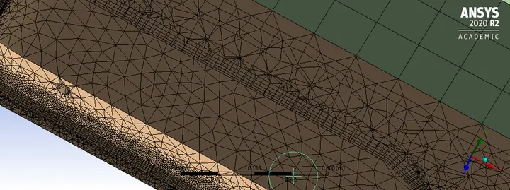
(c) Inflation Layers (Y+)
To catch the boundary layer near the Ahmed body wall and to generate a body fitted mesh inflation layers are created and its thickness is decided base on Reynolds number.
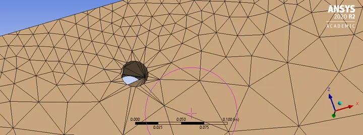
(d) Refinement of projected cylindrical face.
Mesh Independent Test:
After Refining the mesh the solution is made to run for different mesh size and iterations, among this the mesh setup which gives more reliable and converged result is selected for post processing.
Table1: Mesh Independent Test
| Sr. No | Body | Type of Mesh | No of Nodes | No of Elements | No of Iterations |
| Case-1 |
|
|
51426 | 155846 | 350 |
| Case-2 |
|
|
167070 | 432908 | 650 |
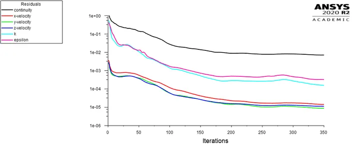
Figure 6 (a). Residual plot for case-1.
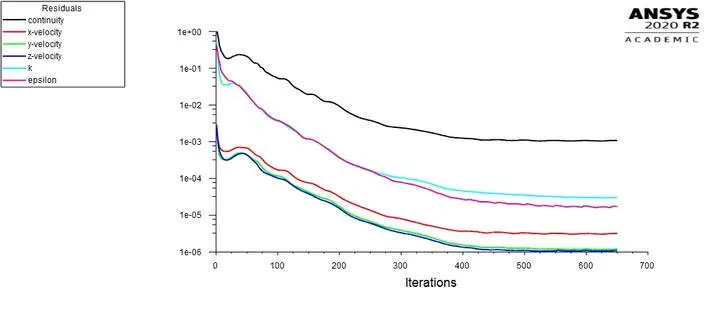
Figure 6 (b). Residual plot for case-2
4. Results:
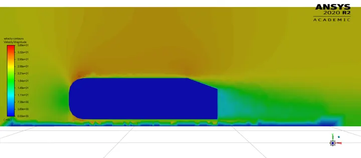
Figure 7 (a) Velocity contours for case-1
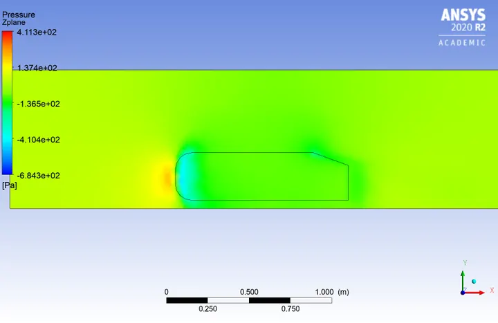
Figure 7(b) Pressure contours for case-1
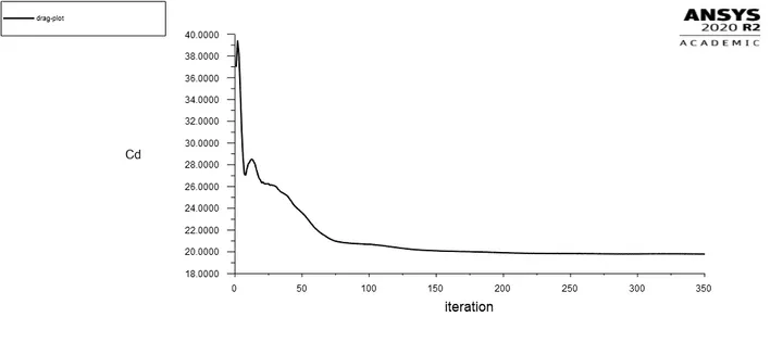
Fifure 7(c) Drag plot for case-1
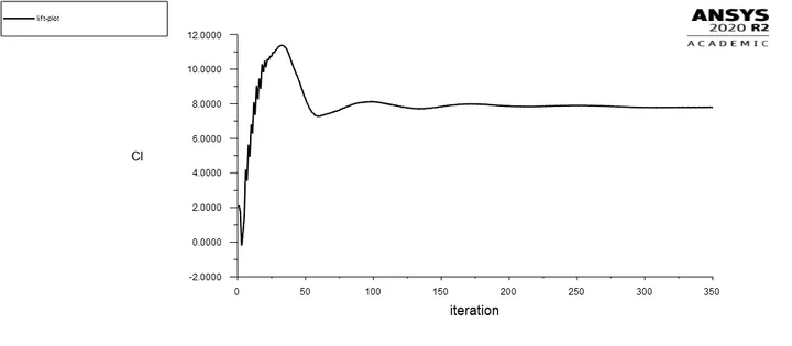
Figure 7(d) Lift Plot for case-1
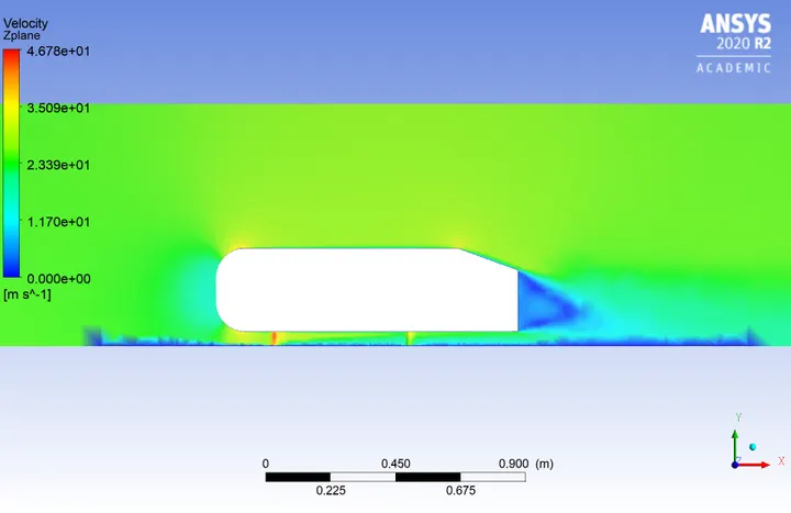
Figure 8(a) Velocity contours with wake region for case-2
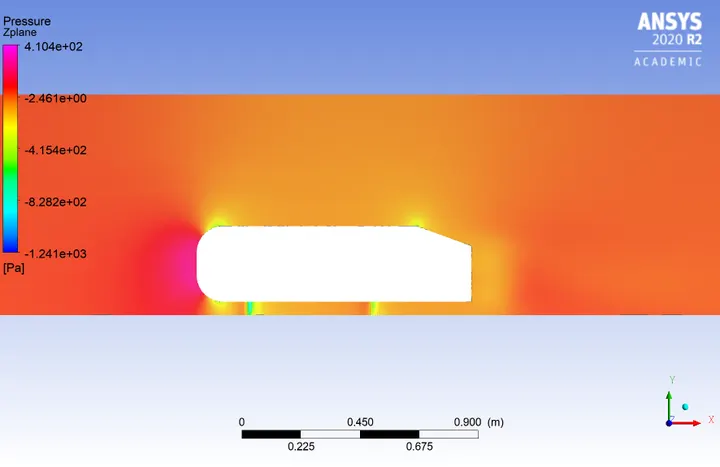
Figure 8 (b) Pressure contours for case-2
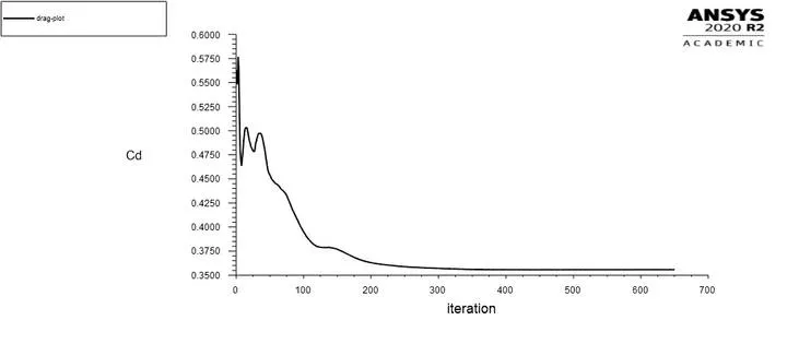
Figure 8(c) Drag coefficient for case case-2
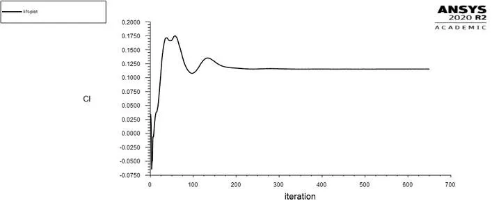
Figure 8(d) Lift coefficient for case-2
Stream lines and Vector Plots for case-2:
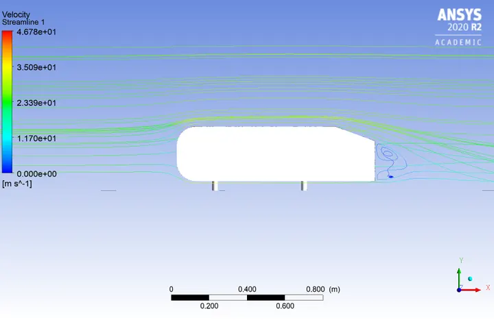
Figure 9 (a) Stream line plot with recirculation zone and sepration zone.
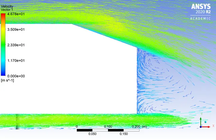
Figure 9 (b) Velocity vector plots with recirculation zone.
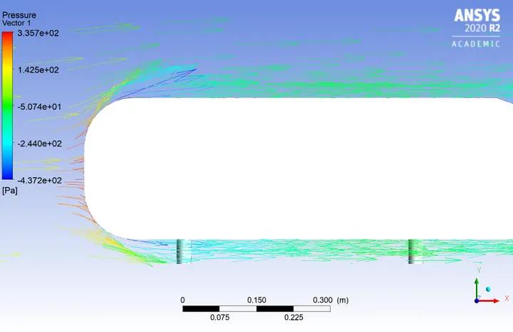
Figure 9 (c) Pressure vector plot at front face of Ahmed body.
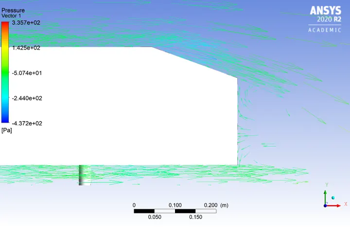
Figure 9 (d). Presssure vector at rear end of Ahmed body.
5. Conclusion:
i. Ahmed body is one of the bench mark problem to analyse the aerodynamic behavoiur of vehicles.
ii. From the obtained results it is found that for velocity of 25m/s the obtained drag coefficient is around 0.35 and lift coefficient is 0.125.
iii. The stream line and vector plots shows that wake region nexists behind the rear end of the Ahmed Body.
iv. A flow sepration region is also seen from the stream line plot.
v. The presence of wake region indicates the negative pressure.
vi. The presence of wake region implies the effect of body on the incoming velocity of the fluid.
vii. At high velocity the fluid detach itself from the body which is called as flow sepration which can be clearly seen in stream line plot.