Simulating Fluid Sloshing effect inside a Gear-box
OBJECTIVE
Perform fluid sloshing simulation in the gearbox for four cases, which include
- 20% Immersion, Fluid - Engine oil.
- 30% Immersion, Fluid- Engine oil.
- 20% Immersion,Fluid-n-heptane (c7h16).
- 30% Immersion,Fluid-n-heptane (c7h16).
THEORY
- Dynamic Meshing
The dynamic mesh model allows us to move the boundaries of a cell zone related to other boundaries of the zone, and to adjust a mesh accordingly. The boundaries can move rigidly with respect to each other (that is, linear or rotational motion) and/or deform. The motion of the boundaries can be rigid, such as piston moving inside an engine cylinder or a flap deflecting on an aircraft wing, or deforming such as the elastic wall of a balloon during inflation, or a flexible artery wall responding to the pressure pulse from the heart.
The nodes that defin the cells in the domain must be updated as a function of time, and hence the dynamic mesh solutions are inherently unsteady. An important special case of dynamic motion is called the sliding mesh in which all the boundaries and the cells of a given mesh zone move together in a rigid body motion. In this situation, the nodes of the mesh move in space (relative to the fixed global coordinates), but the cells defined by the nodes do not deform. Furthermore, mesh zones moving adjacent to one another can be linked across one or more non-conformal interfaces. As long as the interfaces stay in contact with one another (that is, 'slide' along a common overlap boundary at the interface), the non-conformal interfaces can be dynamically updated as the meshes move and fluid can pass from one zone to the other.
The dynamic mesh model in ANSYS fluent can be used to model flows where the shape of the domain is changing with time due to motion on the domain boundaries. The dynamic mesh model can be applied to single or multi-phase flows (and multi-species flows). The update of the volume mesh is handled automatically by ansys fluent at each time step based on the new positions of the boundaries. To use the dynamic mesh model, we need to provide a starting volume mesh and the description of motion of any moving zones in the model.
ANSYS fluent allows you to describe the motion using either boundary profiles, user-defined functions (UDFs), or the six degrees of freedom solver. ANSYS fluent expects the description of the motion to be specified on either face or cell-zones. If the model contains moving and non-moving regions, we need to identify these regions by grouping them into the respective face or cell-zones in the starting volume mesh that we generate. Furthermore, regions that are deforming due to motion on their adjacent regions must also be grouped into separate zones in the starting volume mesh. The boundary between the various regions need not be conformal, we can use the non-conformal or sliding interface capability in ansys fluent to connect the various zoness in the final model.
- Fluid Sloshing Effect
In fluid dynamics, sloshing refers to the movement of liquid inside another object. The liquid must have a free surface to constitute a slosh dynamics problem, where the dynamics of the liquid can interact with the container to alter the system dynamics significantly. Such motion is characterized by an inertial wave. The sloshing of fluid exerts stress and hydrodynamic pressure on the walls of the object and can result in failure of the assembly. In the case of the gearbox, the lubricating oil is subjected to motion due to the rotation of the gears. The restoring forces developed due to the rotational motion of the fluid results in the development of inertial waves. These waves cause irregular fluid flow of the lubricant, affecting its ability to lubricate the gear mesh throughout the range of the motion. Also, the forces and hydrodynamic pressure exerted on the gears and casing due to the sloshing effect could cause wear and tear and reduce the fatigue life of the transmission system. The property which influences the sloshing effect is the viscosity of the fluid. Higher the viscosity, lesser the fatigue life of the transmission system
- User-Defined Function (UDF)
UDF is basically a C program or a C function that can be dynamically loaded with ANSYS fluent to enhance its standard features. The typical features of aUDF are as follows
- must be defined using DEFINE macros supplied by FLUENT
- must have an include statement for the udf.h file
- use predefined macros and functions to access FLUENT solver data and perform other tasks
- are executed as interpreted or compiled functions
- are hooked to ANSYS FLUENT using a graphical user interface dialogue boxes
UDF can be used for a number of applications like
- customize boundary conditions
- material property definitions
- Adjust computed values on once-per-iteration basis
- initialize with a previous solution
- execute at the end of iteration
- upon exit from ansys fluent
- enhance post-processing
- enhance existing ansys fluent models
- Common errors that occur
a) Dynamic mesh failed error
Dynamic mesh fail error refers to situations in which the computational grid changes dynamically during the run of the computational fluid dynamics simulation. This opens up for the possibility to simulate flows where the geometry changes with time.
b) Negative cell volume detected error.
Negative cell volume usually means that the mesh moved too far in single time step so that the cells have collapsed. In other words, remeshing done by the fluent in the dynamic zone is too coarse that the distance moved per time step maybe greater than the edge of cell size in the dynamic region. To solve this error, check whether the named selection of the boundaries is continuous, mesh generated is of high quality, local remeshing parameters. Increasing the time step carefully can solve this error.
PROCEDURE/WORKFLOW
GEOMETRY
- Import the 3D geometry
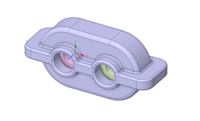
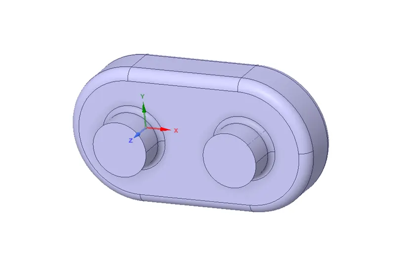
- Extract the fluid Volume
- Prepare->volume extract->select the edges->ok
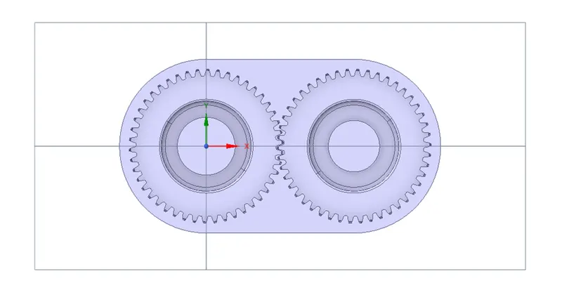
- Split the body in half to extract 2D geometry at the middle plane
- Design-.create plane->click on the origin->split body->click the target object (here extracted volume)->select the plane->click on the region to be removed.
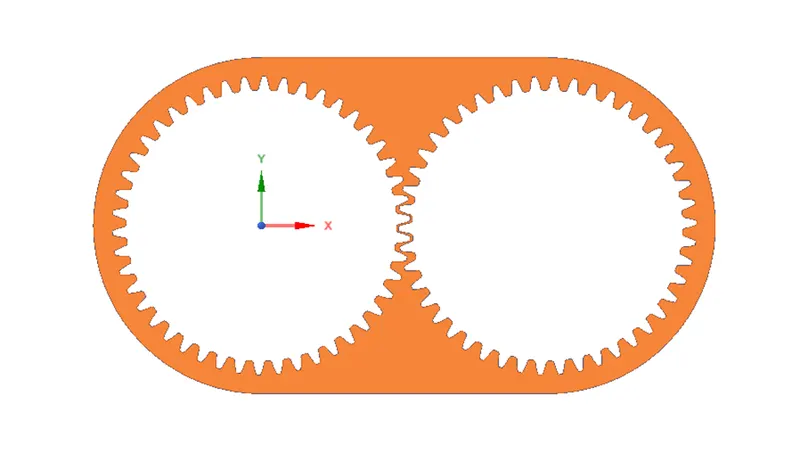
- Select the region outside the gears->copy and paste in a new design window in the XY plane.
MESHING
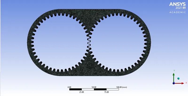
- Insert triangular meshing method
- Insert->method->all triangles method->provide element size->enable capture proximity->number of cells across the gap =1
- Create named selection
- name the gears as left and right
SETUP
- Double precision, parallel processor (4)
- Models
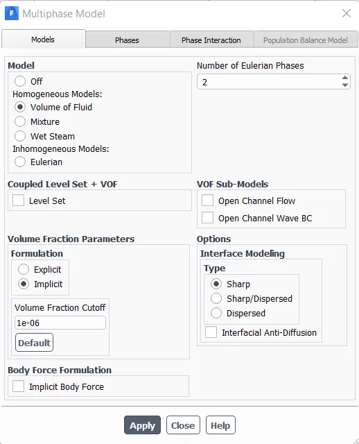
- Multiphase->volume of fluid ->implicit
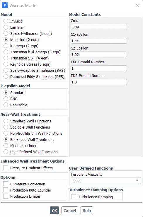
- Viscous model->K-epsilon->realizable->enhanced wall treatment
- Solver
- Pressure based, velocity formulation-absolute
- Transient simulation
- Enable gravity (y =-9.81 m/s^2)
- Mark/Adapt the cells
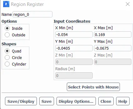
- Setting up domain->refine/coarsen->cell registers->region->new->provide the shape of the region (here, Quad) ->enter the coordinates->define whether the region is inside or outside (here, inside)->save and display
- Materials
- Create materials->fluent data base->select the required materials->copy->create
- Load the UDF
- User defined->function tab->compiled->add->select the file->build->ok-> load
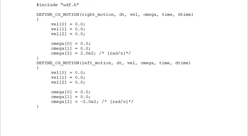
- Setup dynamic mesh
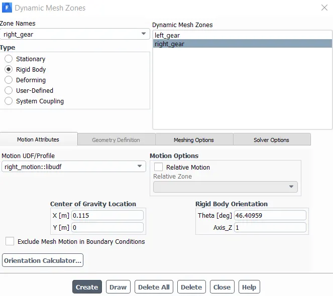
- Setting up domain->dynamic mesh->check smoothing, remeshing-> check the settings->create/edit->motion attributes->select left gear->lgive left motion->create->select right gear->give right motion->provide centre of gravity (here, (0.115,0))->create->close
-
- click on display zone motion to view the motion of the gears->preview
- Initialization
- Enable hybrid initialization
- Patching
- Patch->select phase->volume fraction->select region->provide value =1->patch
- To view the patched area, go to post processing->contours->new->phases->volume fraction->phase->select all ->save and display
- Run
- Provide appropriate time interval, and run for appropriate iterations.
RESULTS AND PLOTS
1. 20% Immersion, Fluid- Engine oil.
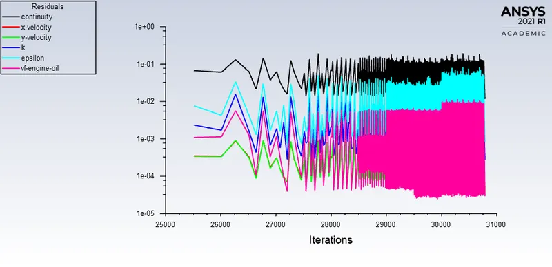
Figure 1: Residuals
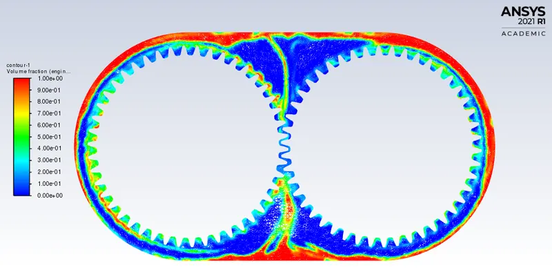
Figure 2: Volume fraction of lubricant at 0.0754 flow time
link: https://youtu.be/g_RFqKMXvj0
2. 20% Immersion,Fluid-n-heptane (c7h16).
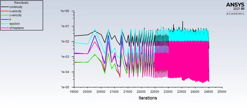
Figure 3: Residuals
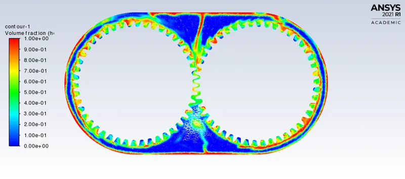
Figure 4: Volume fraction of lubricant at 0.0754 flow time
link: https://youtu.be/O-zopBaSqMg
3. 30% Immersion, Fluid- Engine oil.
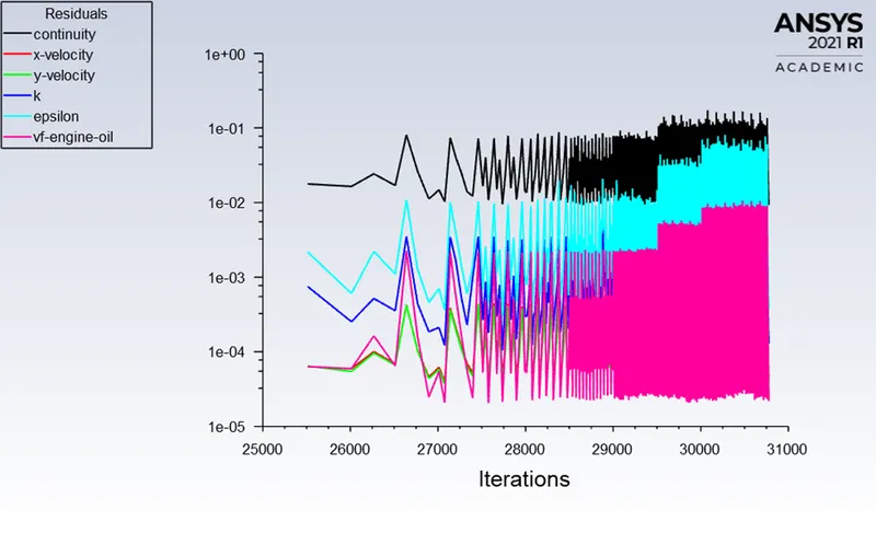
Figure 5: Residuals
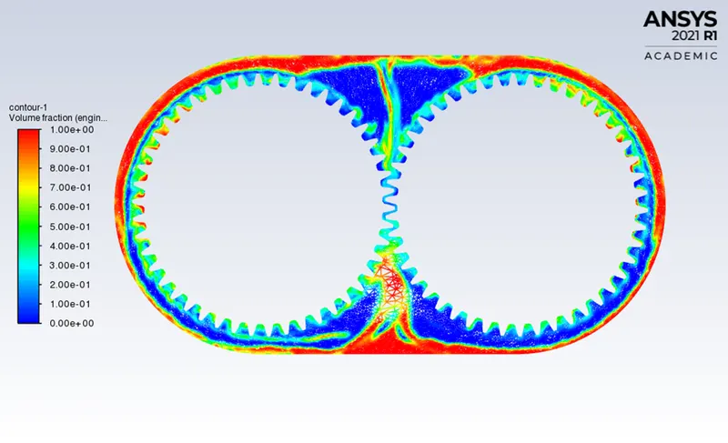
Figure 6: Volume fraction of lubricant at 0.0754 flow time
link: https://youtu.be/4Gl14c0r2uQ
4. 30% Immersion,Fluid-n-heptane (c7h16).
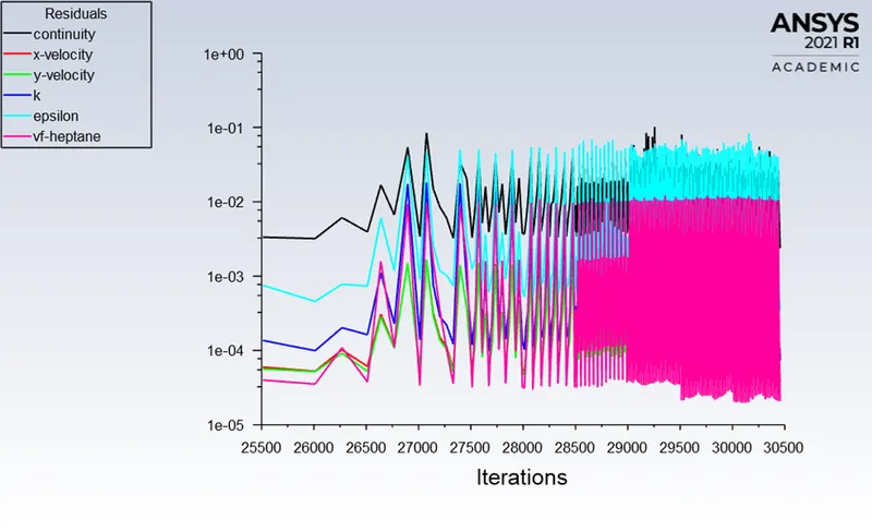
Figure 7: Residuals
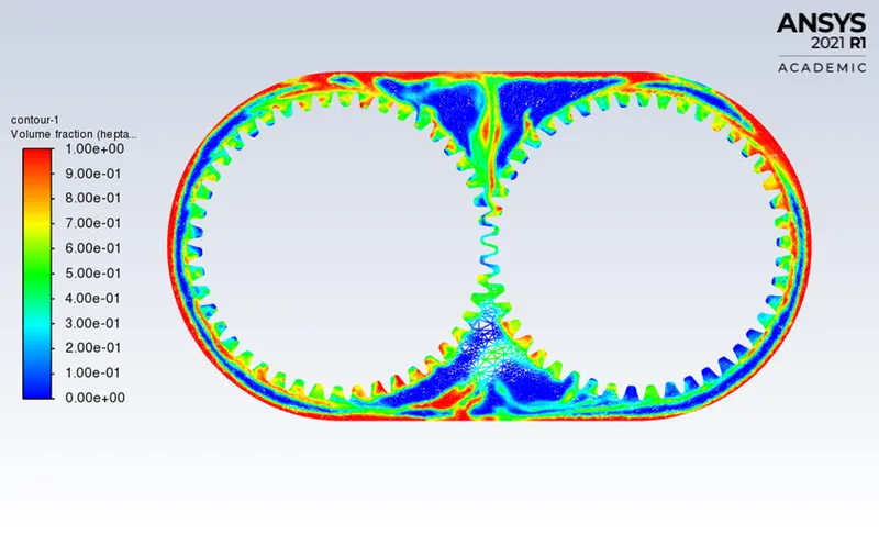
Figure 8: Volume fraction of lubricant at 0.0754 flow time
link: https://youtu.be/aujrzzS1yCQ
CONCLUSION
- The number of gear teeth immersed in the lubricant is more in 30% immersion than the 20%.
- In the case of 20% immersion, the sloshing effect is greater in the case of n-heptane than engine oil. This is because, the the density and viscosity of the former are lower than the latter. However, the lubricant film formation on the teeth is more stable in the case of engine oil because of higher viscosity.
- The availability of lubricant is obviously more in 30% immersion case, so is the number of teeth that are immersed in lubricant. With increased number of rotations, the lubricants can reach all the teeth faster.