Section Modulus calculation and optimization
Aim: To calculate the section modulus of the existing section at the center of the hood assembly. Also, suggest a way to increase the section modulus of the current hood assembly.
Section modulus is a geometric property for a given cross-section used in the design of beams or flexural members. Other geometric properties used in design include area for tension and shear, radius of gyration for compression, and moment of inertia and polar moment of inertia for stiffness. Any relationship between these properties is highly dependent on the shape in question. There are two types of section moduli, the elastic section modulus and the plastic section modulus.
For general design, the elastic section modulus is used, applying up to the yield point for most metals and other common materials.
The elastic section modulus is defined as S = I / y, where I is the second moment of area (or area moment of inertia, not to be confused with moment of inertia) and y is the distance from the neutral axis to any given fibre. It is often reported using y = c, where c is the distance from the neutral axis to the most extreme fibre.
In this case, the hood assembly has some section modulus. It can be calculated using the formula:
`S= I/y`
Where, S = Section Modulus, I = Moment of Inertia, y = distance of extreme fibre of the section from the center.
In NX CAD, the moment of inertia is calculated using the ‘Section Inertia Analysis’ command. For the given condition, the inertia analysis data is shown below:
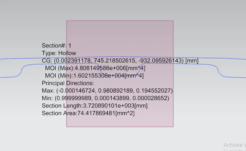
Fig. 1: Inertia Analysis of the current section
Maximum moment of inertia = 4.8081x106 mm4
Minimum moment of inertia = 1.6021x104 mm4
Distance of fibre = y = 440 mm
Thus, section modulus is calculated as follows:
`S_max= I_max/y= (4.8081*〖10〗^6)/440=10927.5 〖mm〗^3`
`S_min= I_min/y= (1.6021*〖10〗^4)/440=36.4 〖mm〗^3`
How to increase the strength of the Hood Assembly by changing the section modulus?
To increase the section modulus, we can either increase the moment of inertia or decrease the distance of the fibre from the center. In this case the distance cannot be changed because it is fixed according to the aesthetic of the car. So we can increase the moment of inertia and the section modulus will improve.
Moment of inertia or second moment of area is directly proportional to the area of the section. So, to increase the area of section, we can use following ways:
- Offset the section curve such that the area enclosed by it is greater than previous condition.
- Increase number of embosses, so that the section at the center has more area enclosed inside it.
Here, we have tried the first method and offset the lower curve by 0.5 mm and the results are as shown below:
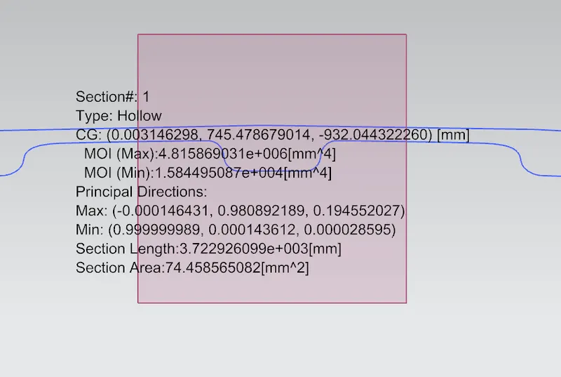
Fig. 2: Inertia Analysis of the improved section
Maximum moment of inertia = 4.8158x106 mm4
Minimum moment of inertia = 1.5844x104 mm4
Distance of fibre = y = 440 mm
Thus, section modulus is calculated as follows:
`S_max= I_max/y= (4.8158*〖10〗^6)/440=10945 〖mm〗^3`
`S_min= I_min/y= (1.5844*〖10〗^4)/440=36 〖mm〗^3`
Conclusion:
- By comparing the design section modulus of the optimized hood section increased by 0.1%.
- MOI can be increased by increasing the section area and decreasing the distance between the neutral axis and the farthest fibre.