Section Modulus calculation and optimization
Report On Section Modulus Calculation and optimization Of Hood
OBJECTIVE:
The aim of the project is to find the section modulus using the formula S=I/Y of the designed hood and optimize it to get an improved section modulus by making necessary changes for analyzing its strength and also optimizing the design to see the difference in the bending strength of the hood. Higher the section modulus of a structure, the more the resistive it becomes to bending.
Section modulus
Section modulus is a geometric property for a given cross-section used in the design of beams or flexural members, it is also referred to as the Polar Modulus or the Torsional Sectional Modulus. Other geometric properties used in design include area for tension and shear, radius of gyration for compression, and moment of inertia and polar moment of inertia for stiffness. Any relationship between these properties is highly dependent on the shape in question. Equations for the section moduli of common shapes are given below. There are two types of section moduli, the elastic section modulus and the plastic section modulus.
S=I/Y
Here,
S = Section modulus
I= Moment of Inertia (Unit mm 4)
Y= Distance from Neutral axis to the extreme end (unit mm)
The Unit of a “section modulus” is (mm3)
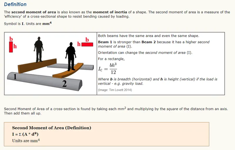
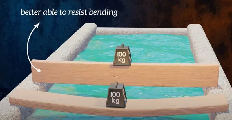
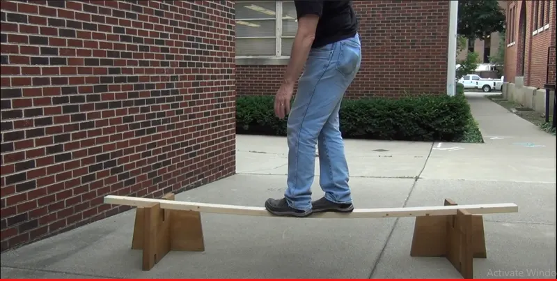
Changing the position can show the difference in bending which is because of the centroid distance from extreme fiber end.
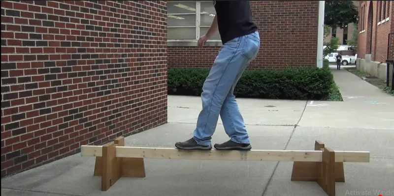
In Layman's terms, in this position there is more material from axis to the specific direction, to resist the load which makes less bend and improves the strength.
SECTION MODULUS
- Elastic Section Modulus
- Plastic Section Modulus Elastic Section Modulus



Hood assembly - Sectioin Modulus:
Here below image is my hood assembly.
Here first i would check section modulus from the front side impact strength check, it does mean load wil be apply from front side so i have made datum plane accourdingly,
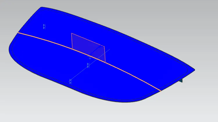
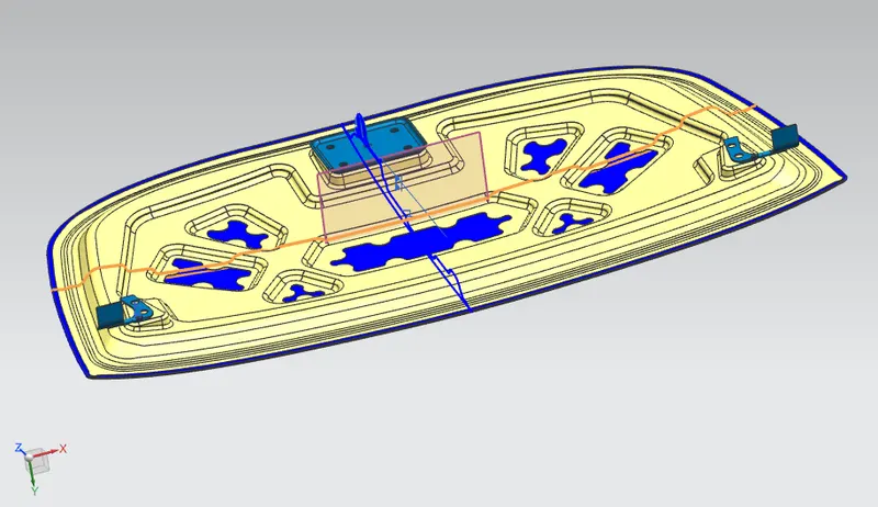
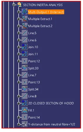
To create cross section of the hood assembly, I did use curve on datum then made profile help of tool curve intersection.
Then I have made sketch with help of projection, and studio spline for gap filling by poles.
Then with help of section inertia analysis tool via found the below value of my hood.
First Design Study
The Intersection of the design was taken and then section Inertia Analysis was done-
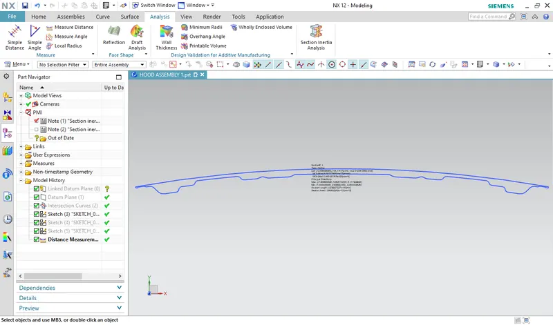
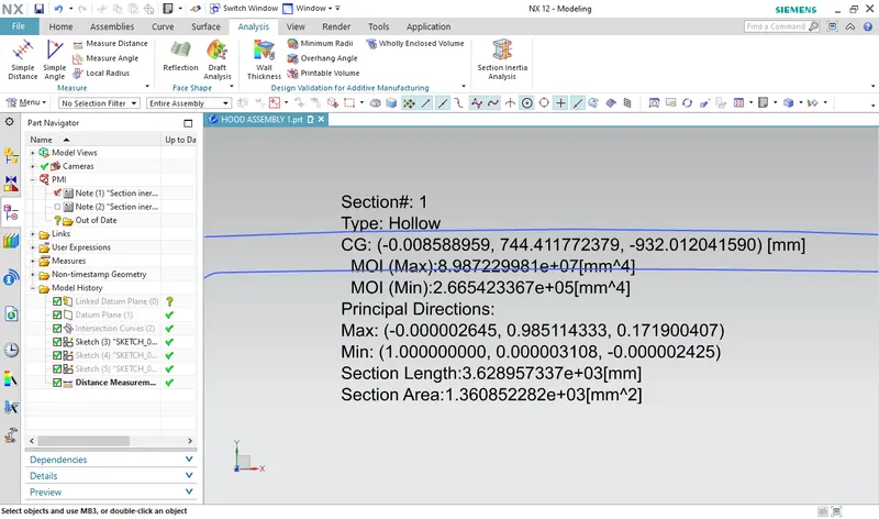
Moment of inertia(max) = 8.987229981e+7×mm^4
Moment of inertia(min) = 2.665423367e+5×mm^4
NOTE: we always consider minimum Moment of inertia(MOI) always considering factor of safety.
Y=876.3740/2=438.187 mm
Z1=I/Y
Z1=2.665423367e+5/438.187 = 395.58/438.187 = 0.9027mm3
Hood Design Optimization
By increasing the depth of the inner panel by 0.5 mm
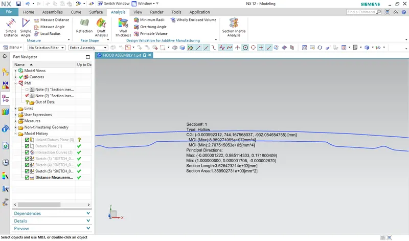
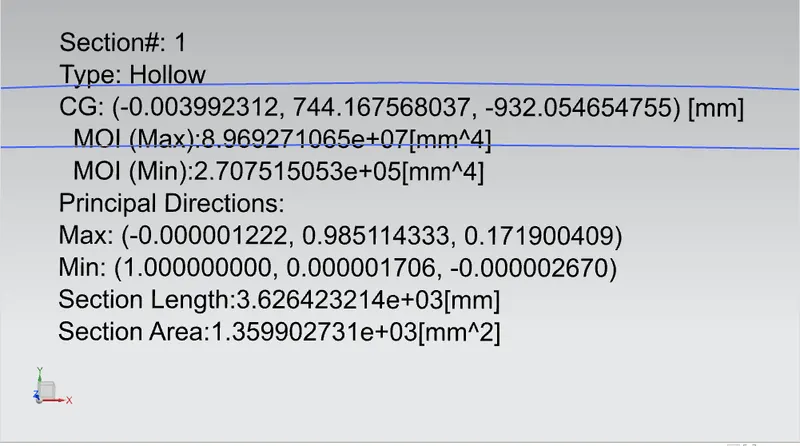
Moment of inertia(max) = 8.969271065e+7×mm^4
Moment of inertia(min) = 2.707515053e+5×mm^4
NOTE: we always consider minimum Moment of inertia(MOI) always, considering factor of safety.
Y=876.3740/2=438.187 mm
Z2=I/Y
Z2=2.707515053e+5/438.187 = 401.830/438.187 = 0.917mm3
Z2=0.917mm3 > Z1=0.9027mm3
So we can improve our hood via strengthen our hood inner panel by increaseing the deep of the emboss deep / Hood inner panel deep.
Here I have checked the section modulus for load applying the front side of the vehicle in this same way we can check the section modulus to applying th load from side of the vehicle.

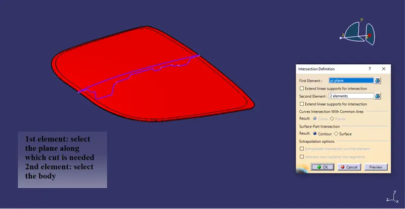
Current hood:
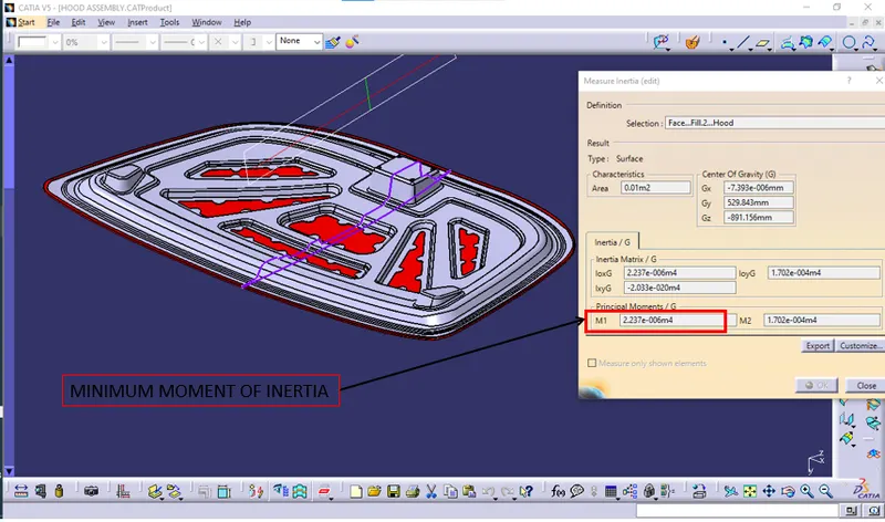
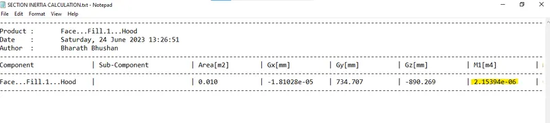
Moment of inertia(min) = 2.154e-06m4
NOTE: we always consider minimum Moment of inertia(MOI) always, considering factor of safety in CATIA M1 is minimum moment of inertia.
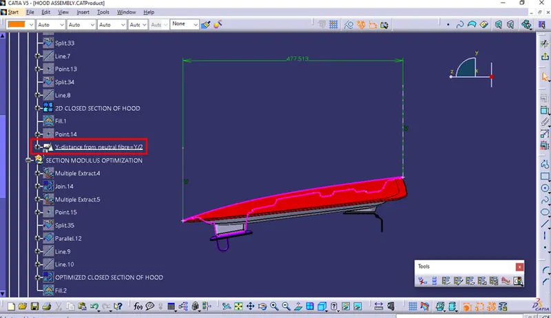
Y=477.513mm/2=238.7565 mm=0.2387565 m
Z1=I/Y
Z1=2.154e-06/0.2387565 = 0.005339/0.2387565 = 0.02236m3
Now we going to improve the moment of inertia as much as better and then will check again to find out differences how our hood improved.
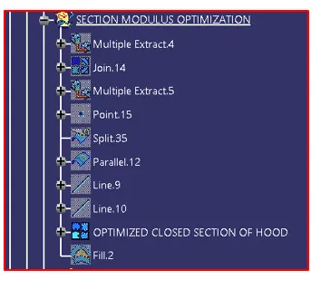
New improved hood:
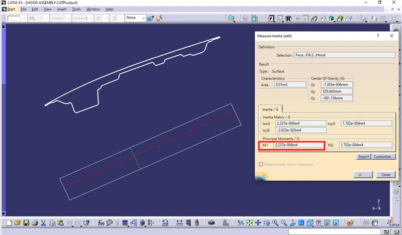
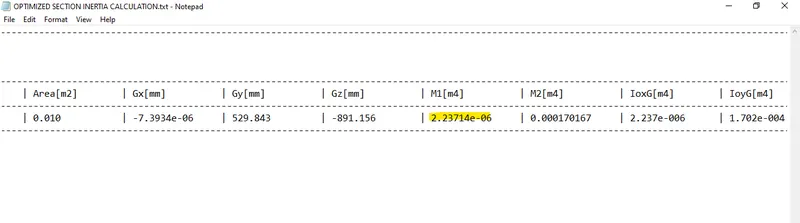 Moment of inertia(min) =2.23714e-06 m4
Y=477.513mm/2=238.7565 mm=0.2387565 m
Z2=I/Y
Z2=2.23714e-06/0.2387565 = 0.005545/0.2387565 = 0.023224m3
TREE STRUCTURE:
Conclusion
So, here the difference can be seen in the moment of inertia and the change in the section modulus can be seen by the change in the design(depth).