Section Modulus calculation and optimization
Aim:
To calculate the section modulus of the Hood design.
Objective:
To obtain the section modulus of the designed hood panel and the new improved section modulus better than the earlier one.
Theory:
Section modulus is a geometric property for a given cross-section used in the design of beams or flexural members. There are two types of section moduli, the elastic section modulus, and the plastic section modulus. For general design, the elastic section modulus is used, applying up to the yield point for most metals and other common materials.
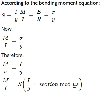
The elastic section modulus is defined as
S = I / y,
Where,
S = Section Modulus
I = Moment of Inertia
y = distance between the neutral axis and the extreme end of the object
For example, if the steel component has a high section modulus, it will be harder to bend and can resist high moments having high bending stress.
As per the formula, we need to divide the maximum bending moment by the section modulus to get the bending stress and then compare the bending stress with the allowable tensile stress that the steel can take the required moment of force.
Section modulus is inversely proportional to the bending stress, which means sections having higher section modulus have lower bending stress.
Procedure:
Case 1:
First, we find the intersection of the Hood panel by taking the YZ plane
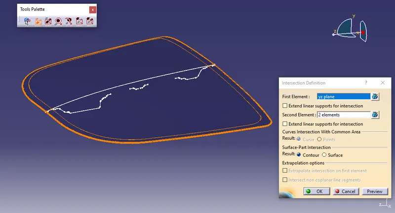
Next use multiple extracts to the outermost boundary of the inner and outer hood panel.
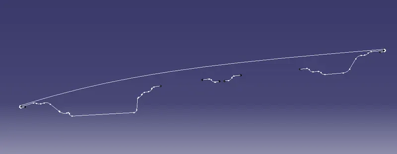
- Then draw a line to join them to create a closed profile.
- After that fill it by using the Fill command.
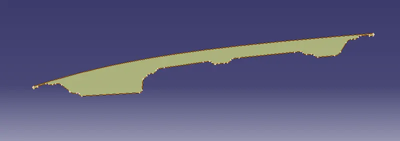
Now measure inertia by 2D of the surface and the minimum value of the M will be the moment of inertia.
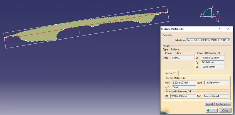
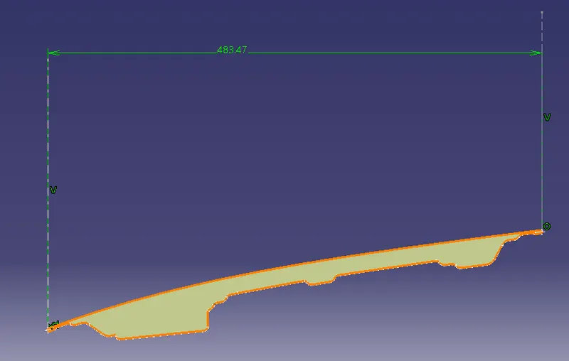
- We also need to calculate the distance between the neutral axis and the extreme end which is Y.
- Go to the sketch and take a point on the two extreme ends of the curve and draw a straight line parallel to the vertical axis and constraint both lines so that we get the distance between them.
Here,
M1 = 9.908e-007m4
M2 = 1.627e-004m4
By taking the minimum value from the two value
Unit is converted from meter to millimeter
`M1=990799.9mm^4`
`Y=483.47/2`
`= 241.73`mm
putting these values in the formula we have got the section modulus for the hood,
`S=I/Y`
`S=990799.9/241.73`
`S=4098.78mm^3`
Case 2(Improved section):
For the improved section, we are going to offset the outer curve of the inner panel by 0.5mm so that it results in an increase of the inner area and ignoring the thickness of the hood.
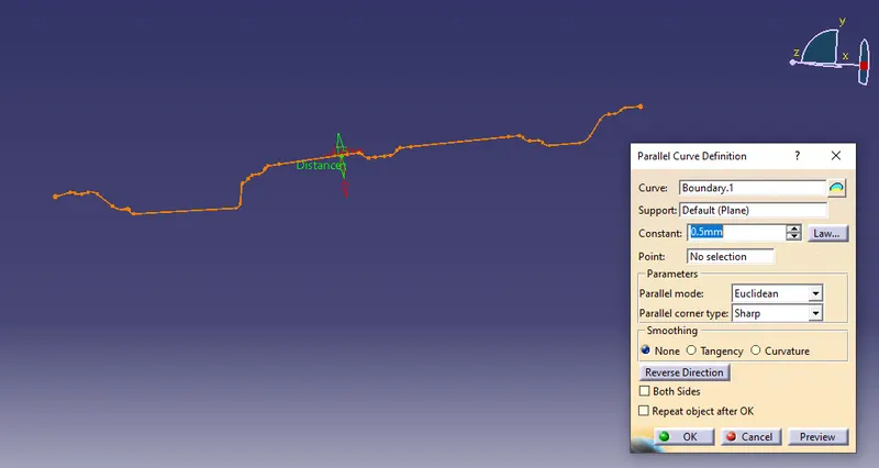
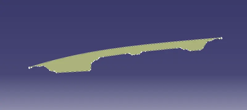
Do the same operation to get a closed profile and measure the inertia of the improved section.
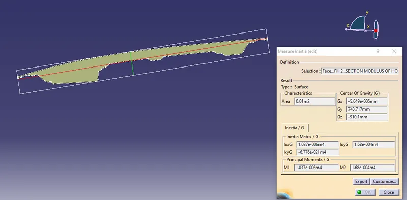
Here,
M1 = 1.037e-006m4
M2 = 1.68e-004m4
By taking the minimum value from the two value
Unit is converted from meter to millimeter
`M1=1037000mm^4`
`Y=483.47/2`
`= 241.73`mm
putting these values in the formula we have got the section modulus for the hood,
`S=I/Y`
`S=1037000/241.73`
`S=4289.91mm^3`
Results:
| Moment of Inertia, I(`mm^4`) | Length of the section `(mm)` | Y=Length/2`(mm)` | Section Modulus, S`(mm^3)` | |
| Case 1 | 990799.9 | 483.47 | 241.73 | 4098.78 |
| Case 2 | 1037000 | 483.47 | 241.73 | 4289.91 |
Conclusion:
The above chart shows that the Section modulus of Case 2 is greater than Case 1.
It shows the strength of the component is increased in Case 2, but it also depends on the designer to choose the best option from the calculations which gives satisfactory results.