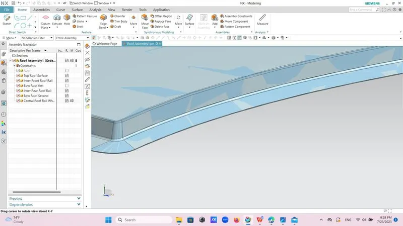
Roof Design
Report on Roof design
Step 1: Download part provided ,open this file in NX Cad,also download all master sections which are provided .
Step 2:Select new file and choose assembly and named it as Roof Assembly.
Outer Roof Rail :-
Step 3:Create new model named it as Outer roof and then by using wave geometry linker from option form Ribbon bar from assembly tool bar extract body of roof panel ,then untrimmed its half surface and then with respective before one surface boundary trimmed it particularly alongside of roof surface by using trim sheet option, then as per master section there is inclined surface by an angle of 7deg.as no measures were provided so took it as arbitrary as 16mm. and by using law extension command and edge as curve drew it as .then as per master section there is provided as horizontal surface of about 21mm but no angle was provided so that I took it as 20 deg and by using law extension command drew this surface.as per front view drew side view also by taking side edge as curve and by using law extension command and by distance of 16mm with and angle of 7 deg given in front side also drew a surface with this surface again and law extension command drew a horizontal surface also with 21.6mm distance and so gap created in between two corners which then after using bridge curve and swept command joined with linked surface by the help of sew command.
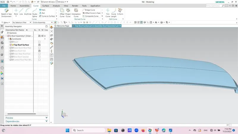
Step 3:-
INNER FORNT ROOF RAIL:-Took new model named it as front roof rail and then through wave geometry linker extract top surface of the inner roof rail then took a plane with point and curve and offset it by a distance of 80mm from that point and through curve option intersection curve intersect that plane with surface and then by using curvature of this plane and face as surface through through point option intersect that curve with intersect curve and and then offset that surface by distance of 32mm and then trimmed this surface with intersection line and trimmed this surface with intersection curve then by choosing front edge and surface and by taking an angle of 20deg drew 16mm line then took horizontal line of 21mm and make corner option from extend and trimmed surface trimmed that surface and joined by sewing operation and then give fillet to it of 2.2mm .
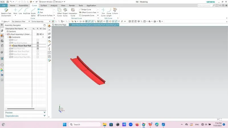
Step 4:-
BOW ROOF FIRST:-Took new model and named it as bow roof first then go to assembly through ribbon bar and click on wave geometry linker option then extract top surface of body which is required for creation of roof then offset this surface by distance of 5+0.75+0.75 and offset ed this plane respectively by and distance of 3mm each to get successive planes. because top roof surface thicken in downward direction then took on curve option and then took a distance of 35mm from corner and then project it by curve -project curve option and intersect this plane with surface the by using this intersected curve offset ed it by distance of 20-15-10 on side of the curve .
Now by using law extension command and angle as 7 deg extend that surface and horizontal surface and then by using make corner option and trimming it with two surface for each plane then sew all this and gave filler 2.2mm.
Ditch area creation :-By using wave geometry linker extract side area of body and then by taking one plane by using datum plane option from home at distance cut it one both side then offset it by distance of 85mm and distance of 0.75+2+0.75 then drew some parallel lines on it by distance of particular distances and by using offset in curve option then by using bridge curve option joined two lines of surface and ditch area plane and by using through curve option drew this ditch area surface.
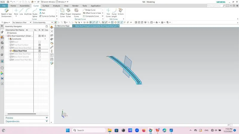
Step 5:-
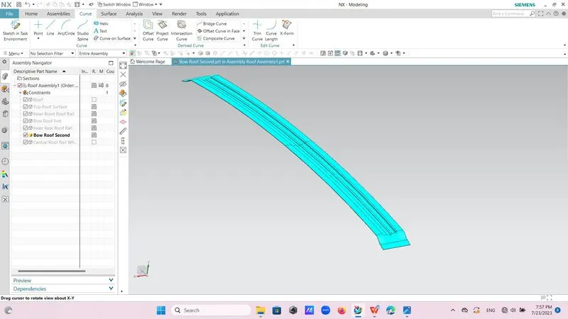
BOW ROOF SECOND:-Took new model and named it as bow roof second then go to assembly through ribbon bar and click on wave geometry linker option then extract top surface of body which is required for creation of roof then offset this surface by distance of 5+0.75+0.75 and offset ed this plane respectively by and distance of 3mm each to get successive planes. because top roof surface thicken in downward direction then took on curve option and then took a distance of 35mm from corner and then project it by curve -project curve option and intersect this plane with surface the by using this intersected curve offset ed it by distance of 20-15-10 on side of the curve .
Now by using law extension command and angle as 7 deg extend that surface and horizontal surface and then by using make corner option and trimming it with two surface for each plane then sew all this and gave filler 2.2mm.
Ditch area creation :-By using wave geometry linker extract side area of body and then by taking one plane by using datum plane option from home at distance cut it one both side then offset it by distance of 85mm and distance of 0.75+2+0.75 then drew some parallel lines on it by distance of particular distances and by using offset in curve option then by using bridge curve option joined two lines of surface and ditch area plane and by using through curve option drew this ditch area surface.
Step 6:-
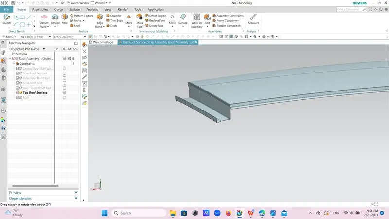
OUTER REAR ROOF RAIL:-Again choose outer roof rail and go to its end portion click on surface and law geometry option then took an angle of 75 inward direction and of arbitrary length then offset top surface by80
mm distance an then by using law extension command and trimmed and extend command and make a corner .
Agin using law extension command and making and angle of 15deg made another surface of length 25 *25 mm and by using make corner option trimmed those surfaces.
Step 7:-
INNER REAR ROOF RAIL:-Create new model named it as Inner rear roof rail then go to assembly and did wave geometry linker and extract surface as body then go to surface and offset surfaces with respective of given values of master section by distance of (3+0.75*2) and (5+0.75*2) and then again and last one of 80+10.75 by distance of 80mm measured .also by using outer rear roof rail and used wave geometry linker and offset that surface by distance of 0.75*2 to get offset portion .Then by using law extension option from surface and extending all the surfaces trimmed off excess portion by using make corner option crate inner rear roof rail.

Step 8:-
CENTRAL ROOF WHEN SUN ROOF IS PRESENT :-
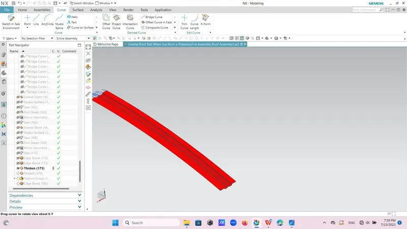
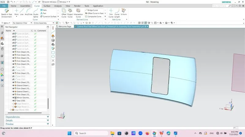
Create new model and named it as central roof then by using wave geometry linker through assembly extract parent body surface and then took a plane by selecting on curve option then go to curve and select intersection curve intersect that plane with surface and then by offsetting this intersection line by distance of 20-15-10-15-20 offset that curve then offset this surface particularly as per given master section as inner and outer bow roof inner and outer bow roof we are connecting by mastic gum so kept distance between then as 0.75 mm .
Now took a plane parallel to first plane and offset it by distance of 90mm ,then again extract side surface and offset it by distance of 0.75mm downward because outer roof rail and ditch area we are joining with spot welding
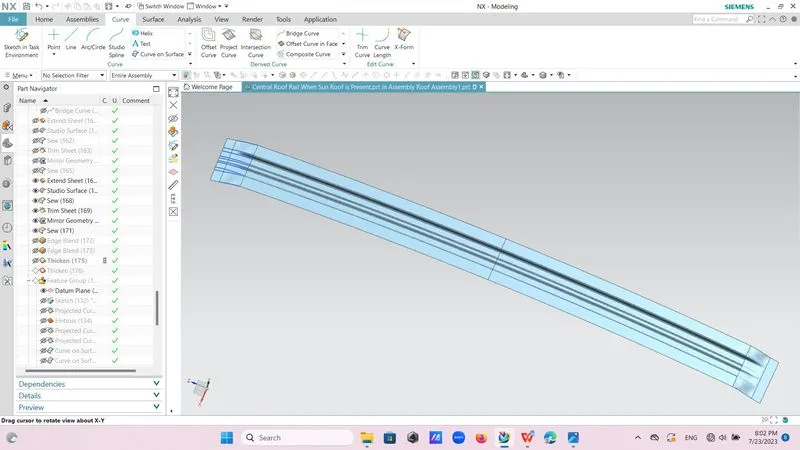
Sun Roof :: Took a datum plane with distance and then go to sketch and drew a sketch of 480*450 mm and then project it on surface then go to surface -more -emboss and embossed it by and distance of 5mm and took an angle of draft of 8deg. And then fillet it particularly .
Then go to sketch again and offset it by distance of 10mm inward so to make flanges then go to trim and trimmed them and also trimmed inner rectangle also.
Step 9:-
Mirror Geometry :Here go to menu -insert - associative copy - mirror geometry option and choose each surface separately and mirror its associative copy for each .
Step 10:-
Thicken : -Now go to the surface and choose option thicken to thick all the surfaces by distance of 0.75 mm each for outer surface is in downward direction and inner surface in upward direction.