Roof Design
Roof Design
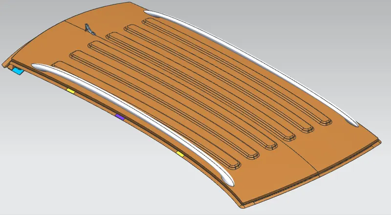
The conventional task of the roof panel is that of compartment shielding and connection of body sides, front and rear roof cross members. In the case of roll over, compartment integrity is provided by the compartment frames.
Any roof panel material requires braces to prevent panel flexing and vertical waviness, commonly known as oil canning; for this purpose, light steel bows are introduced, which are welded or screwed to the body side and bonded to roof panel by smooth flexible adhesives such as butyl mastic (in order to avoid sink marks on outer surface).
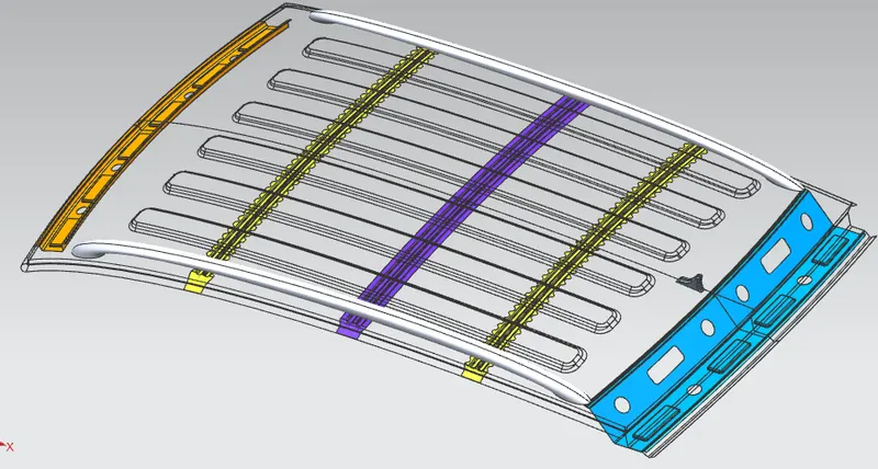
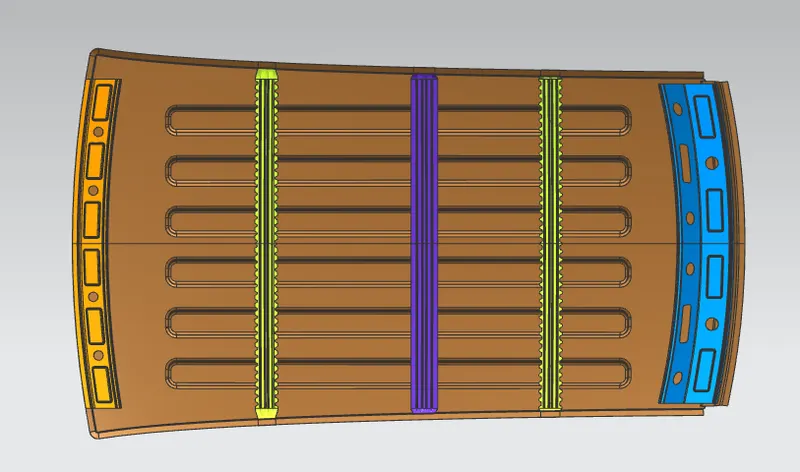
The roof panel along with the outer roof panel, has at least two bow roofs and a centre rail roof along front and rear roof rails. Front roof and rear roof rails are fixed to the ditch area using spot weld operation.
Design Considerations
- Crashworthiness
- Driver visibility criteria
- Head room clearance.
- Bow roof positions.
- Heat distortion criteria and Snow load criteria.
- Draft analysis for ease of manufacturing.
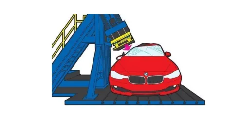
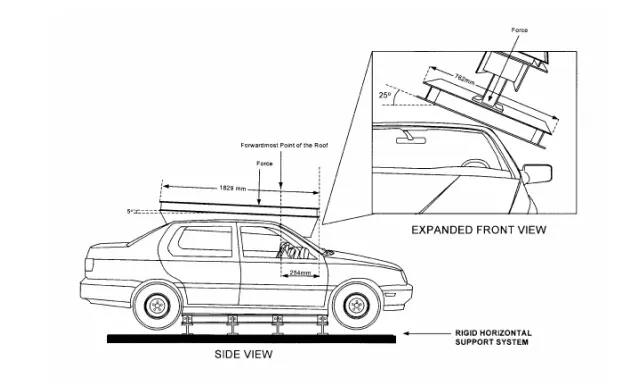
- Crashworthiness is the ability of a structure to protect its occupants during an impact. The vehicle roof strength is measured through the FMVSS 216 test. In this test the quasi-static load is subjected to the vehicle roof structure by a rigid puncher and the amount of intrusion and force-time history are recorded. The roof of the car must have high strength to resist the crush force to avail the passenger some space for survival. And the rigid plate is used to crush the car roof as specified by FMVSS216 standards. The rigid plate is oriented on the car roof as specified by Insurance institute of highway safety (IIHS).
- A test device (rigid unyielding block with its lower surface formed as a flat rectangle 762 mm wide by 1829 long, should not move more than 127 mm, measured as the distance between the original location of the lower surface of the test device and its location as the specified force level is reached, when it is used to apply a force of 1.5 times the unloaded vehicle weight (UVW) or 22,240 N, whichever is less, to either side or forward edge of the vehicle.
- Both the left and right front portions of the vehicle’s roof structure shall be capable of meeting the requirements. The passenger car’s sill or the chassis frame should be placed on a rigid horizontal surface and fixed rigidly in position. The force should be applied in a downward direction perpendicular to the lower surface of the test device at a rate of not more than 13 mm per second until reaching a force of 1.5 times the unloaded vehicle weight. The test should be completed within 120 seconds.
Other tests specified for roof assembly are static, dynamic and impact. The purpose of static testing is to verify that the roof assembly exhibits no permanent deflection due to a distributed load representing snow load. Impact testing is performed on the assembled body, in accordance with regulations. For these properties it is not easy to provide standard design specifications: finite element analysis represents the best approach to reach an appropriate design solution."
Roof Outer Panel
The outer panel is the aesthetic part of the car. This is the part which sits directly above the passenger compartment. It protects the inside of the car from wind, rain, and snow.
With the roof skin as the styling input and master sections for roof rails, the roof panel is designed. Embosses are provided along the length of the roof to give more strength to the part in order to overcome the failing snow load condition.
Front Roof rail:
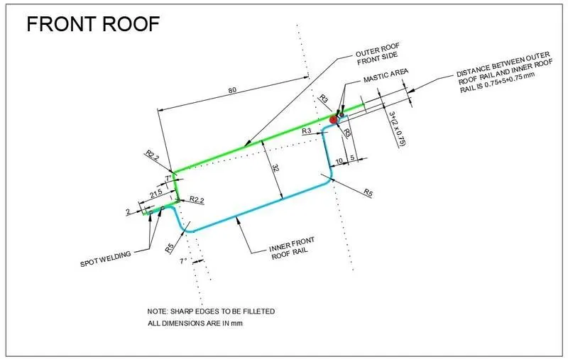
The front rail underpins the roof panel at the front end. The one end of the front rail is joined with the outer panel by spot welding and rest of the part is joined by mastic sealants. Front roof rail is also the part which attaches with the front windscreen; hence it must be carefully designed to allow enough tolerance for joining windscreen onto it with mastic sealants and while doing so it has to be ensured the visibility criteria is not depreciated. Careful consideration must be given while determining the span of the roof rail since it affects the head room clearance. Starting from the styling point a minimum of three-degree draft angle must be maintained to enable deep drawing of the roof outer panel and front roof rail itself. Filleting the sharp edges for at least 2-3mm will increase the life of the tool. Embosses are provided to increase the strength while cut-outs are provided to decrease the weight of the part. The thickness of the front roof rail is 0.75mm.
Rear Roof Rail:
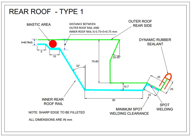
Rear roof rail is like front roof rail provided in the rear, which attaches to the backdoor. Head room clearance of minimum 85mm must be maintained and clearance should be given to enable rear visibility criteria. Similarly, in rear roof rail embosses are provided to increase the strength while cut-outs are provided to decrease the weight of the part.
Bow Roof Front:
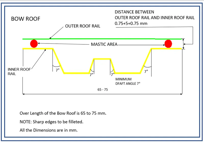
The bow roofs are given to the improve the torsional stiffness and load bearing capacity of the roof structure. As the length of the roof increases, providing more bow roofs becomes a necessity. In the design of this roof, we are providing two bow roofs. Positions of the bow roofs are decided by the curvature study. The Heat distortion criteria and Snow load criteria are determined to analyse the bow roof position. One more consideration for positioning of bow roof is its local flatness. Bow roofs are provided at the region just below where the roof has maximum flatness to improve the strength of the roof. While designing the bow roof, Mastic area are provided for fixing the Bow roof to the roof outer panel. Thickness of the Bow roofs are 0.75mm.
Centre Roof Rail:
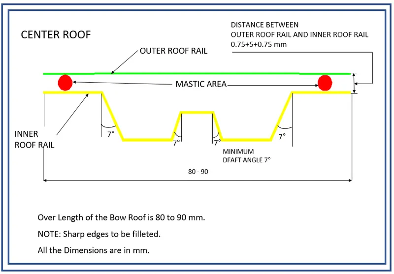
Centre area of roof is susceptible to failure under action of load, hence centre roof rails are provided. Additionally, roofs having sunscreen in the roof are provided with reinforcement rail along with centre roof rail and fixed with B – Pillar support structure. Thickness of the centre roof rail is 0.75mm.
Modelling Roof Panel in NX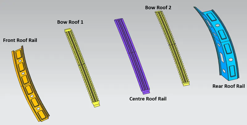
Mastic sealants for Roof:
Mastic sealant is a type of liquid sealant that cures in an elastic state, thus making it flexible while holding the bond of the surfaces that has been attached to it.
Since Roof outer panel is an aesthetic feature, spot welds on the surfaces must be avoided, hence it must be attached to roof rails with the help of mastic sealants. It is a paste, which hardens upon heating in a furnace. Mastic sealant has the tendency to significantly increase the strength of the panel. Surfaces do not have to be primed when using this type of sealant and has waterproofing quality. Most mastic sealants will work well with metal as they do not corrode over time.
Curvature Study
Heat Distortion Criteria:
Heat distortion limit is the temperature limit above which sheet metal materials cannot be used for structural application. Basically, it tests the stiffness of a material as the temperature increases. This study is helpful in finding where the material starts to soften when exposed to a fixed load at elevated temperature. In order to avoid bending, which damages the roof based on the heat distortion temperature, this study will enable to decide the position for placing the bow roof rail and centre roof rail while giving enough strength to support the roof.
Procedure:
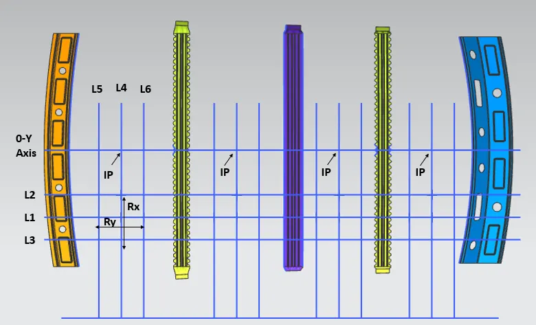
- First a sketch is created with 0-Y axis. This line is offset for 300mm along -Y. This will be L1.
- Then, L1 is offset for 100mm on either side parallel to 0-Y axis. Lines formed are L2 and L3.
- The edges of bow roof and roof rails are projected to intersect with 0-Y Axis.
- From the intersection points formed on 0-Y axis and projected edges, draw a line from inside edge of the front roof rail to outside edge of bow roof. Similarly connect bow roof and centre roof rail and bow roof 2 and centre roof rail.
- From the Midpoint of the lines drawn (IP), draw perpendicular lines to 0-Y axis. This will be L4.
- Offset L4 for 100mm on either side to form L5 and L6.
- The intersection points formed by L2 with L4, L1 with L4, L5 and L6, L3 with L4 are projected on to the roof surface. The radial-distance from L2 to L3 on L4 will be Rx and radial-distance from L5 to L6 on L1 will be Ry.
Heat Distortion criteria calculation:
W = [1.73 x 10^ (-3) x L] + [1.85 x 10^ (-8) x (R^2)/2] + [1.10 x 10^(-3) x I] -2.68
Judgement Condition: OK if it is < 2.7 (less than 2.7)
Where,
L= Roof Length in X- direction [mm] (Roof Dimension in 0-Y)
R = Roof curvature R = 2(RX*RY)/(RX+RY)
Rx = X Curvature Ry = Y Curvature
t = Roof plate thickness [mm] I = Bow roof span [mm]
Snow Load Criteria:
Snow load criteria study is used to check the ability of the roof to withstand snow fall on the roof and whether the deformation is elastic or plastic, i.e., if the roof regains its original shape after the snow has been cleared off the roof.
Procedure:
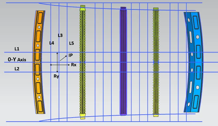
- First a sketch is created with 0-Y axis. This line is offset for 100mm parallel in either direction. These lines will be L1 and L2.
- The edges of bow roof and roof rails are projected to intersect with 0-Y line.
- From the intersection points formed on 0-Y line and projected edges, draw a line from oytside edge of the front roof rail to inside edge of bow roof. Similarly connect bow roof and centre roof rail and bow roof 2 and centre roof rail.
- From the Midpoint of the lines drawn (IP), draw perpendicular lines to 0-Y axis. This will be L3.
- Offset L3 for 100mm on either side to form L4 and L5.
- The intersection points formed by L1 with L3, 0-Y line with L3, L4 and L5, L2 with L3; projected them on to the roof surface. The radial-distance from L1 to L2 on L3 will be Rx and radial-distance from L4 to L5 on 0-Y axis will be Ry.
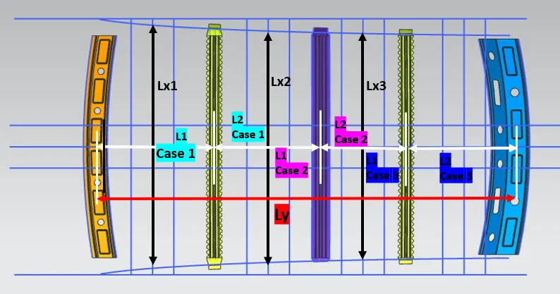
Snow load calculation:
Qr = (Iy x t^2) / (α x s x ((Rx + Ry) / 2) ^2 x 10⁻⁸)
Where,
α = My* Lx^2*10^-12 and My = Y(Ly-Y)
Judgement condition = Qr > 3.1
t = Roof plate thickness[mm]
Ly = Distance between the front and rear roof rails on the vehicle along with 0Y.
Length of roof panel with the centre point between roof rails front/ rear as the front and rear reference point.
Lx= Distance between the left and right end of the roof on the roof bow[mm], With of the roof panel exposed on the surface.
Y = Distance between Front roof rails to roof bow [mm],
s = Distance for which roof bow bears divided load [mm],
s = L1/2 + L2/2
Iy = Geometrical moment of inertia of roof bow (Y cross – section) [mm^4],
Rx = Lateral direction, radius of curvature of roof panel along Y cross section on roof bow [mm^4],
Ry = Longitudinal direction, radius of curvature of roof panel along X cross section on roof bow [mm^4]
Since the Snow load criteria is failing, additional embosses are given on roof outer panel to strengthen the roof
Moment of Inertia of Bow Roofs and Centre Roof Rail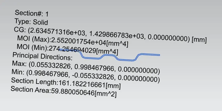
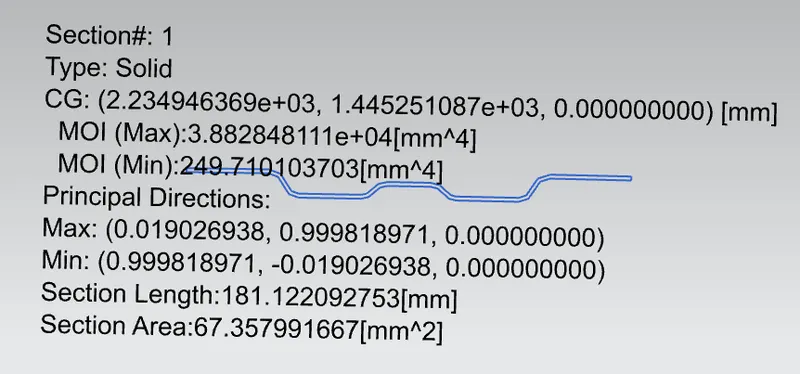
Bow Roof 1 Centre Roof Rail
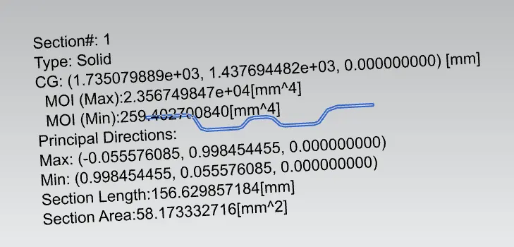
Bow Roof 2
Draft Analysis:
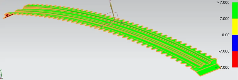
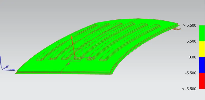
Since all sheet metal parts formed are deep drawn and go through embossing, proper draft angle to perpendicular walls is to be provided to ensure easy removal of the part from mould must be ensured. Draft analysis is performed and any deviation from the minimum draft angle will be shown in red colour. Minimum draft angle is three degree is considered for analysis. Green colour shows positive draft angle of the part of more than three degrees.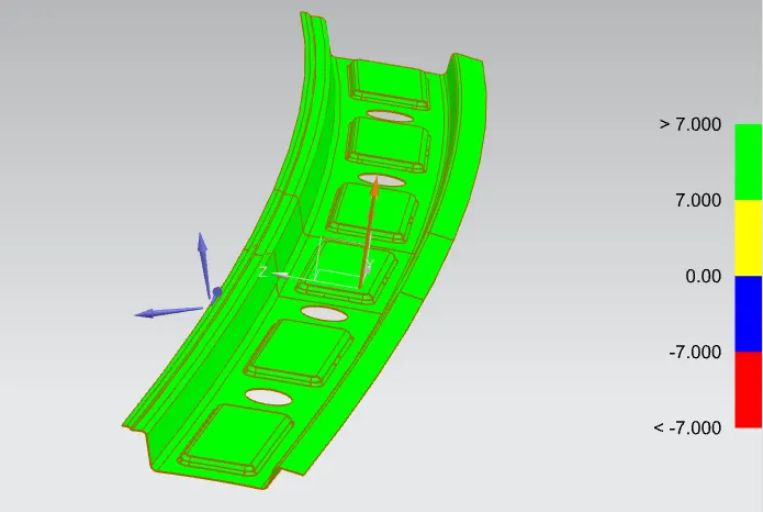
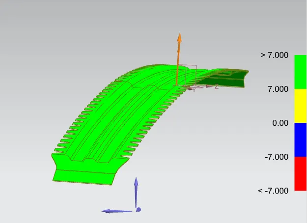
Front Roof Rail Bow Roof 1
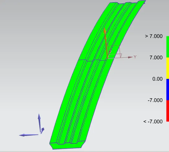
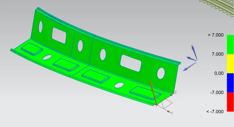
Centre Roof Rail Rear Roof Rail
Bow Roof 2
Roof Outer Panel
Assembled model