Roof Design
AIM
- For the given Roof styling, we need to create an ASSEMBLY by designing and developing the essential flanges for the outer roof and creating the reinforcements.
OBJECTIVE
- This project deals with the detailing of roof introduction, types, roof components, design consideration for roof and proper explanation of procedures followed to design the roof components. In this project the master section was given for the reference along with the parameters for the hood design. Here, the master section was given for reference and parameters were also included in that master section for designing the roof. Finally, the draft analysis were performed on every component to check the manufacturing feasibility.
METHODLOGY
- Develop the roof outer surface with the help of master section.
- Creating the front roof rail and rear roof rail with embosses on it.
- Creating the Bow rails ( bow roof 1, bow roof 2) with the help of master section.
- Creating reinforcement and center roof rail.
- Performing the curvature analysis (Heat distrotion and Snow load calculations).
- Performing feature draft analysis on each components.
INTRODUCTION
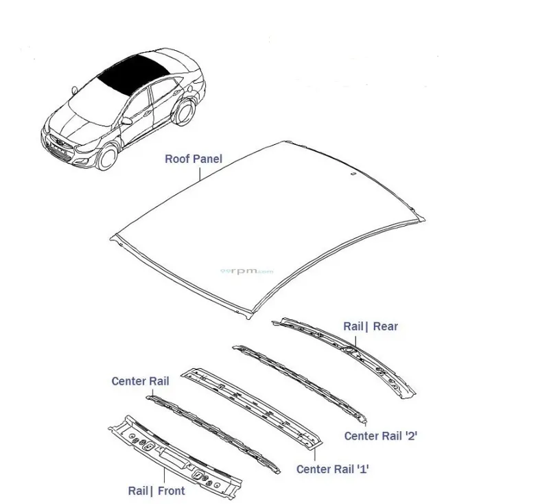
- An automobile roof or car top is the portion of an automobile that sits above the passenger compartment, protecting the vehicle occupants from sun, wind, rain, and other external elements.In addition to that it also contributes to the overall structural integrity of the car and helps to keep the occupants safe in the event of an accident.
TYPES OF ROOFS
- Hardtop roof
- Sun roof
- T-top roof
- Moon roof
- Convertible roof
- Retractable hardtop roof
HARDTOP ROOF
- A hardtop is a rigid form of automobile roof, typically metal, and integral to the design, strength, and style of the vehicle.
- In limited cases a hardtop roof can be detachable (often designed to store in the trunk), or retractable within the vehicle itself.
SUN ROOF
- A sunroof is a movable panel that opens to uncover a window in an automobile roof, allowing light and fresh air to enter the passenger compartment. Sunroofs can be manually operated or motor driven, and are available in many shapes, sizes and styles.
T-TOP ROOF
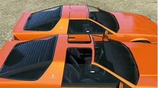
- A T-top is an automobile roof with a removable panel on each side of a rigid bar running from the center of one structural bar between pillars to the center of the next structural bar. The panels of a traditional T-top are usually made of auto grade safety glass.
MOON ROOF
- A moon roof has a glass panel that is transparent and usually tinted.
CONVERTIBLE ROOF
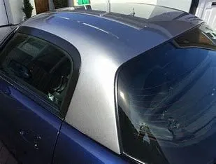
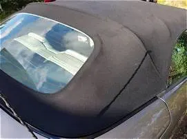
- The convertible roofs are of a folding construction framework with the actual top made from cloth or other fabric. Other types of convertible roofs include retractable hardtops ,often constructed from metal or plastic and detachable hardtops where a metal or plastic roof is manually removed and often stored in the trunk.
RETRACTABLE HARDTOP ROOF
- A retractable hardtop also known as coupe convertible or coupe cabriolet is a car with an automatically operated, self-storing hardtop, as opposed to the folding textile-based roof used by traditional convertible cars.
ROOF COMPONENTS
The following are the components of the roof,
- Roof outer
- Front roof rail
- Bow roof rails
- Center roof rail
- Reinforcement
- Rear roof rail
ROOF OUTER
- Roof outer panel mainly protects from external objects and abnormal environmental conditions. All the pillars are spot welded around the roof & roof rails. Welding on upper surface is avoided for the best aesthetic look. It is the major styling portion of the assembly made up of sheet metal.
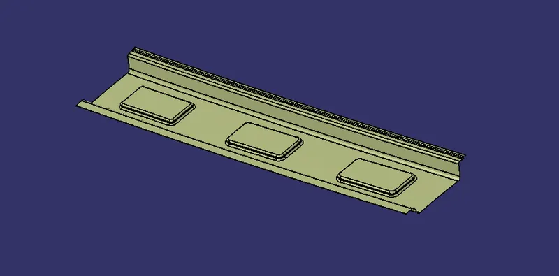
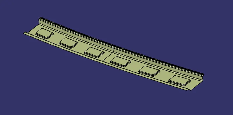
FRONT ROOF RAIL
- This rail acts as frontal support for the roof and joined with the frontal windshield glass. This is joined with the help of mastic sealants.
BOW ROOF RAILS
- The bow roofs are made to provide support or strength to the roof. They are also joined using mastic sealants.
CENTER ROOF RAIL
- The center roof rail are made to provide the structural interigity at the center of the roof. This is also joined using mastic sealants.
REINFORCEMENT
- If the sun roof is provided then the reinforcement is made above the center roof rail to provide the strength.
REAR ROOF RAIL
- It acts as rear support for the roof and it is attached with the C or d pillar. joined used the mastic sealants with the outer roof.
DESIGN CONSIDERATION
The following are the considerations to design a roof.
- Head clearence
- Front visibility / Rear visibility
- Material
- Nunber of bow roof rails
- Sun roof
- Joining techniques
- Shape
- Curvature Analysis
- Roof cruch test
HEAD CLEARENCE
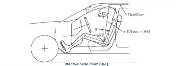
- Its is measured as the distance from a car’s roof to its seat bottom. For every car the head clareance distance differs.
VISIBILITY (FRONT / REAR)
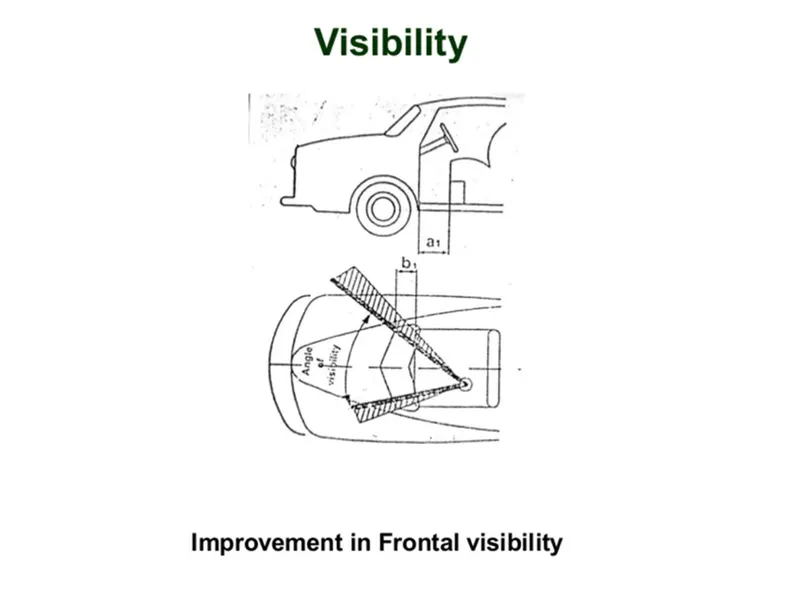
- It depends on the window opening and their relative position to the occupants. If occupant is placed close to wind screen the forward visibility is considerably improved but comfortable entry is adversely affected as dimension between pillar and seat is decreased requiring suitable shaping of the door, if possible.Downward visibility can be improved by positioning the driver as high as possible in retaliation to the lower edge of wind screen. Rearward visibility is achieved by increase in glass area required to maintain rear view vertical angle with back window.
NUMBER OF BOW ROOF RAILS
- The bow roof rails are provided to support the roof or in other words it provides structural strength. If the number of bows are more the more strength the roof will get.They are attached to the pillars of the car( A,B,C &D).
SUN ROOF
- If the sun roof are provided then that region will become week i.e, there will not be more strength compared to other regions.So the reinforcmentsare provided on the center roof rail to get extra support to the roof.
JOINING TECHNIQUES
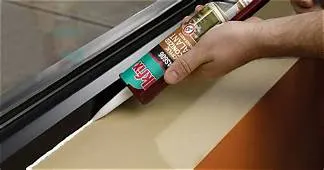
- The outer roof and the other components are joined using
- Mastic sealants can act as a protecting layer between elements. The features of this sealant and how it works makes it different from the others. It forms a smooth exterior which makes the surface flexible while maintaining a hard plastic beneath the surface. For mastic sealants the clearence should be 5 mm.
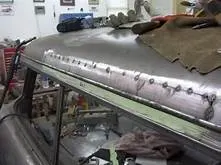
- Spot welding is done on two metal sheets as they are placed them one on the other with the zero clareence distance. Its a types of resistance welding.
SHAPE
- The shape of the roof plays a role while designing, where the strength depends on it. The shape of the roof decides the bow rails positions for structural strength.
CURVATURE ANALYSIS
- In curvature analysis there are two analysis for calculating. Heat distrotion and Snow load claculations.
- Heat distrotion temperature is the temperature at which materials soften and deforms under a specific load. This study is used to predict the heat distortion temperature at where the materials start to soften when exposed to a fixed load at elevated temperature. In order to avoid bending or damages on the roof, base don heat distortion temperature, this study will predict the bow roof position which help to strengthen the roof.
- Snow load criteria study is done to check the ability of the to withstand snowfall and bounce back to its original shape without any permanent deformation once the load is removed.
ROOF CRUSH TEST
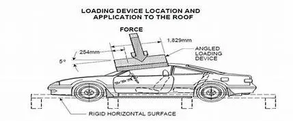
- The roof crush test has been utilized to reduce passengers’ injuries from a vehicle rollover. Features such as electronic stability control are proven to significantly reduce rollovers and lane departure warning systems may also help.
- The Federal Motor Vehicle Safety Standards (FMVSS) 216 and the Insurance Institute for Highway Safety (IIHS) perform actual vehicle tests and evaluate the vehicle’s ratings. Nonlinear dynamic response structural optimization can be employed not only for achievement of a high rating but also minimization of the weight.
PROCEDURE
Data to be considered while designing
- Thickness of each components = 0.75 mm
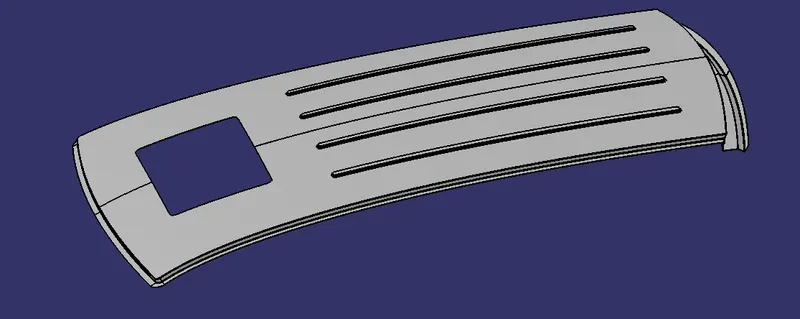
ROOF OUTER
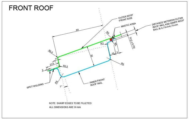
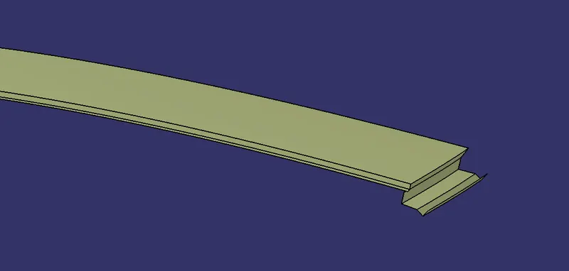
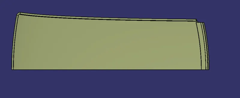
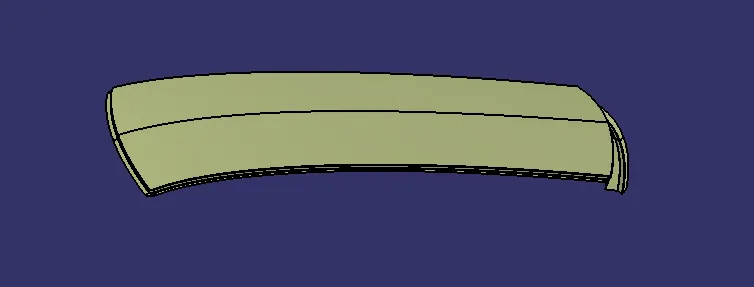
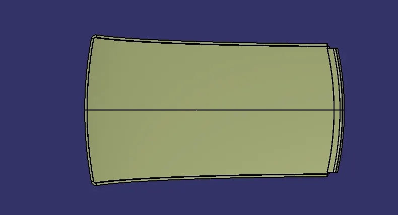
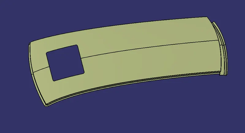
- The green colour sketch is our outer roof dich area master section.
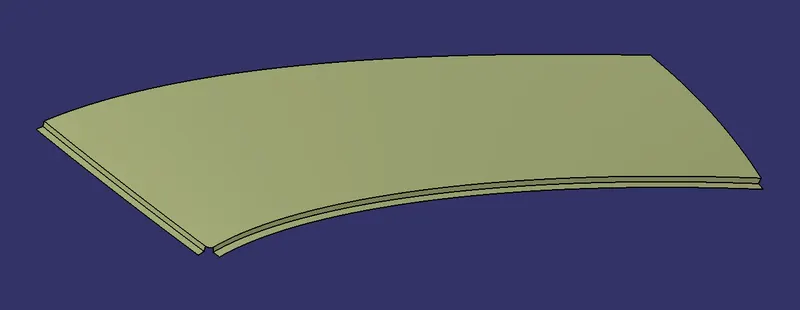
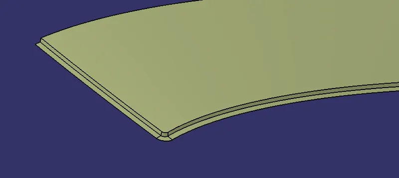
- First the reference outer surface is extracted and then the splited into half with the help of split feature and the datam plane.
- Then, with the help of master section ditch area of the outer roof is made.
- After that, mirror that surface with the center datam plane and use join feature to it. If, there any connectivity error while joining then use extrapolate feature and split it with the center datam plane and now mirror the surface and join them .
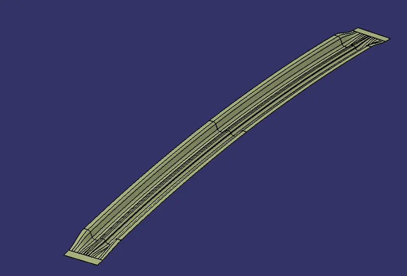
FRONT ROOF RAIL
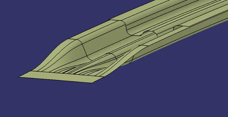
- The blue colour sketch is our front roof rail master section.
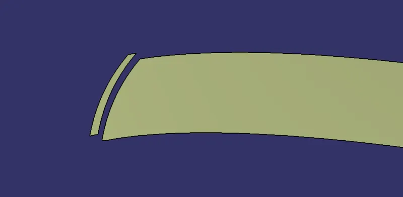
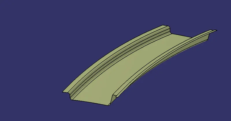
- First, the ditch area was extracted and offseted to height of 1.5 mm and then sweeped to an angle of 7 degree downwards.
- The parallel curve was taken about 2 mm fron the front and splited.
- Then the outer surface was extracted and offseted to th edistance of 32 mm downwards.
- Then the reamining surfaces for the front roof rail was created using sweep, parallel curve, and finally shape fillet features.
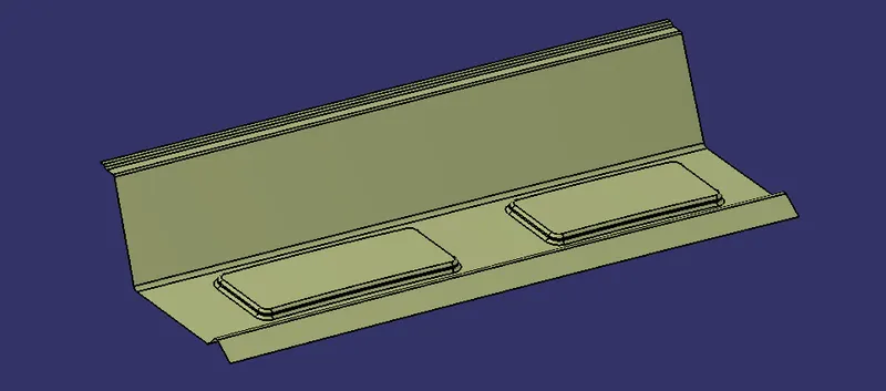
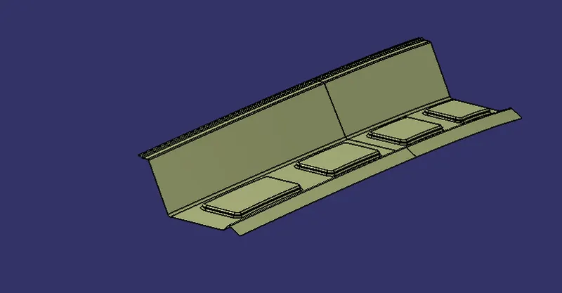
- Now, create a plane on the surface and split it to get the proper shape. Then create embosses on the surface with proper design.
- Finally extropolate the surface th about 10 mm and split it with the help of center datam plane.
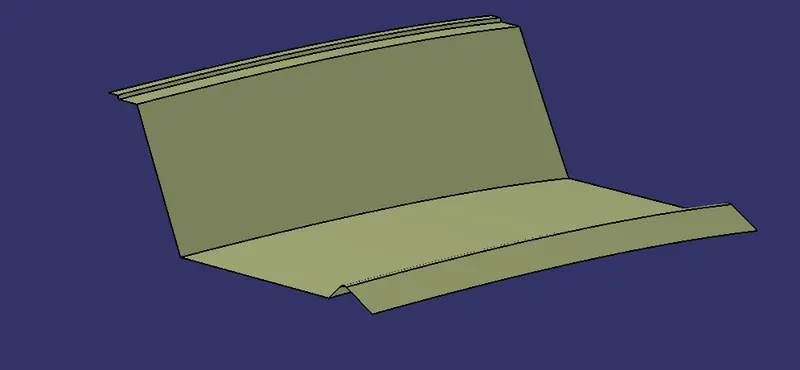
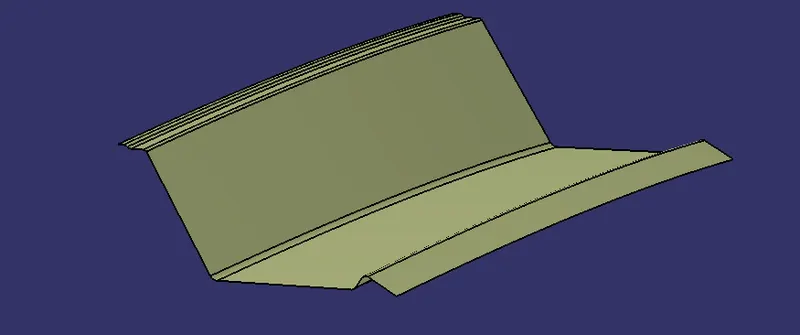
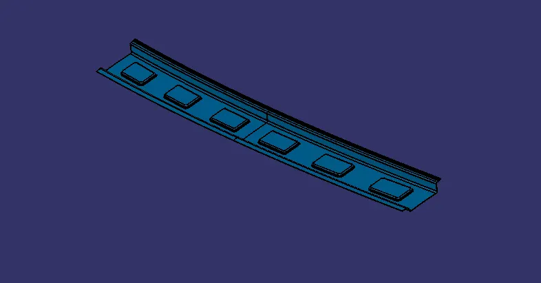
REAR ROOF RAIL
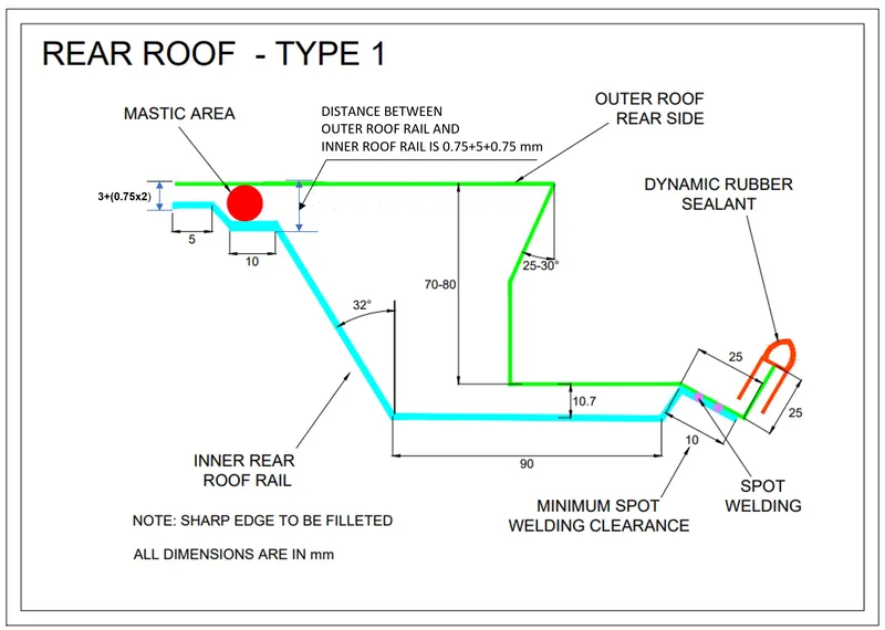
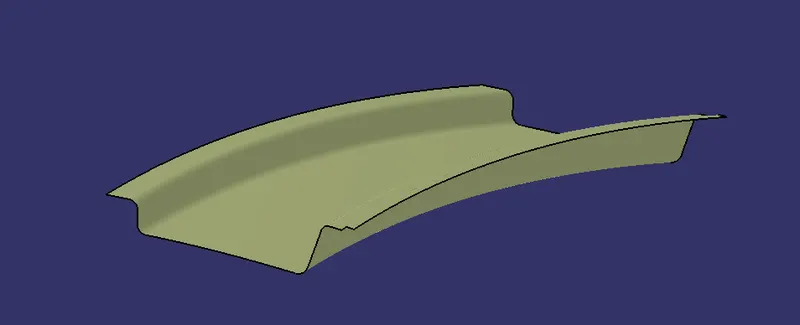
- Same way the master section is used here for creating it.
- Now extract the surfaces which are necessary and then use sweep, extrapolate, parallel curve and shape fillet features to finish the rear roof rail.
- For shape fillet the fillet radius are given in the master section, if not assume the proper radius for it.
- Create an embosses on the surface by using offset, sweep and shape fillet features.
- After that, extrapolate the end edges to about 10 mm and split it with the help of center datam plane.
- Now, mirror the surface and join them using join feature.
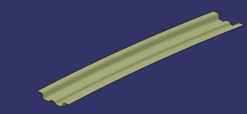
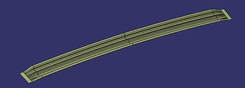
BOW ROOF RAIL 1
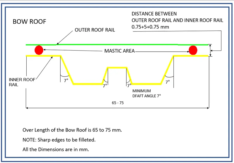
- The master section was used to create the bow rail.
- Create a point on the center line from the end with the distance ration of 0.8. Create a plane on that point using parallel plane option.
- Now use intersect option to the surface and with the plane.
- Extract the outer surface and offset the surface with the distance of 6.5 mm and now project the instesection line on to that surface.
- Use parallel curve option to the required distance and use split feature to split it.
- The ditch area was extracted and offseted to about 1.5 mm .
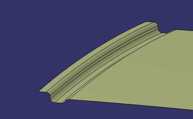
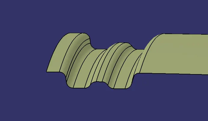
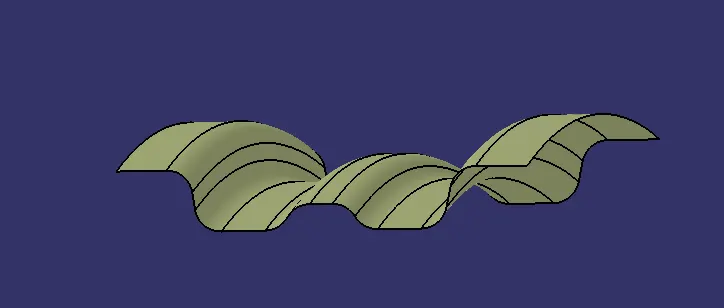
- Same way we need to create the bow roof rail 1 with the sweep, split, offset, shape fillet and parallel curves features according to the given master section provided.
- Finally, extrapolate the surface and split it. Now mirror the surface and join them using join feature.
BOW ROOF RAIL 2
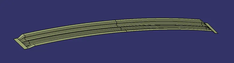
- For this the same master section in bow roof rail 1 is used.
- This is done as the same way as like the bow roof rail 1.
- Instead we need to given the value for the point as 0.25 mm for creating the plane and remaining the same method in bow roof rail 1.
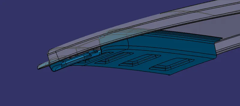
CENTER ROOF RAIL WITH REINFORCEMENT
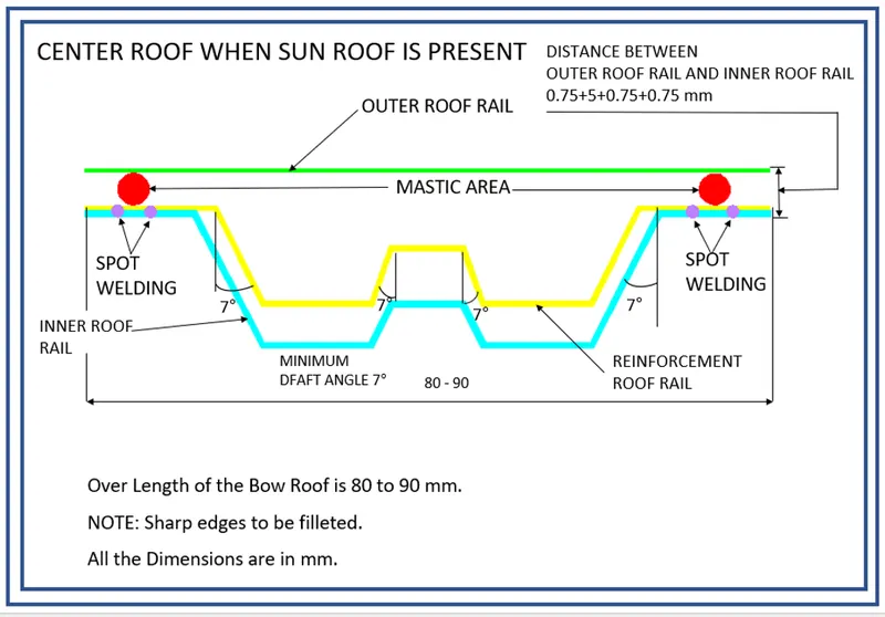
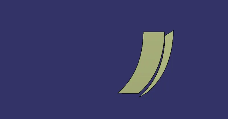
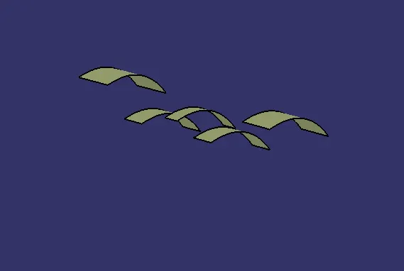
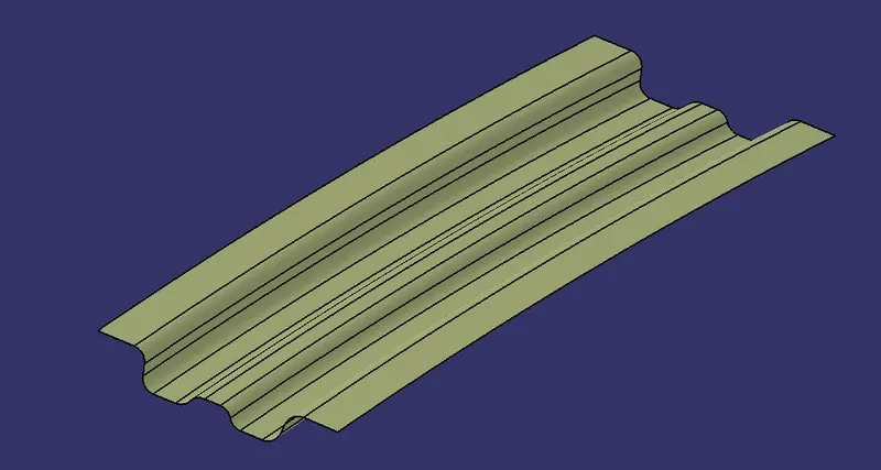
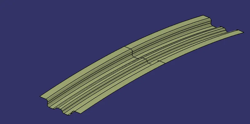
- Here, the yellow colour sketch is our reinforcement mastersection and blue colour sketch is our center roof rail mastersection.
- The center roof rail was created according to the given master section.
- Sweep, offset, split, parallel curve and shape fillet features were the tools used to create this rail.
- After creating the surface mirror it and join the surfaces using join feature.
- The reinforcement was made because the the sun roof was designed on the outer surface.
- The reinforcement master section were also given for designing it.
THICKENED SURFACE
- The surfaces are thickened using the thick surface featurte in the part design.
- The thickness of the all the surfaces were given about 0.75 mm towards the outer surface.
- But the outer surface will be thickened inwards direction.
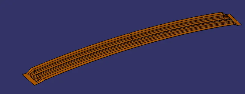
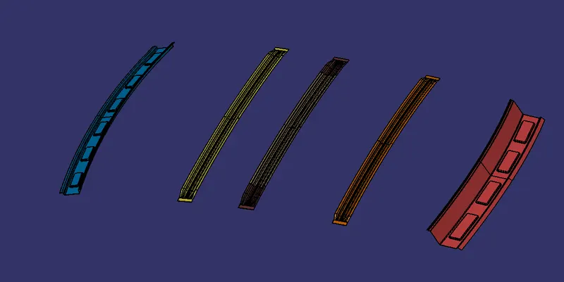
ROOF OUTER
FRONT ROOF RAIL
REAR ROOF RAIL
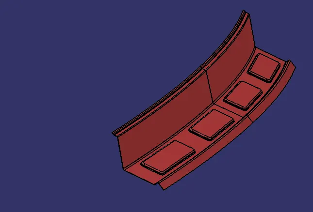
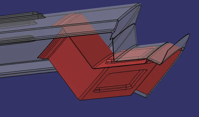
BOW ROOF RAIL 1
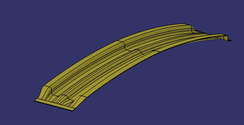
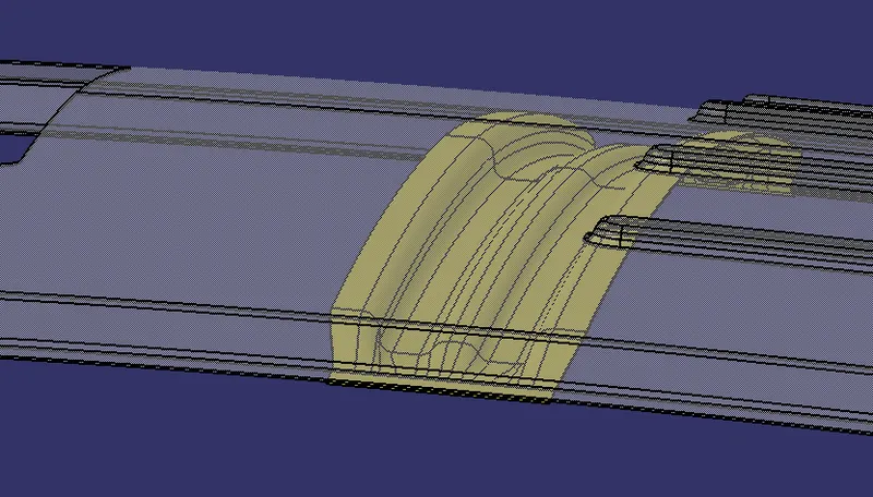
BOW ROOF RAIL 2
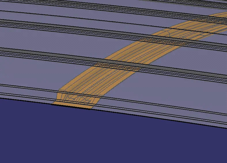
CENTER ROOF RAIL
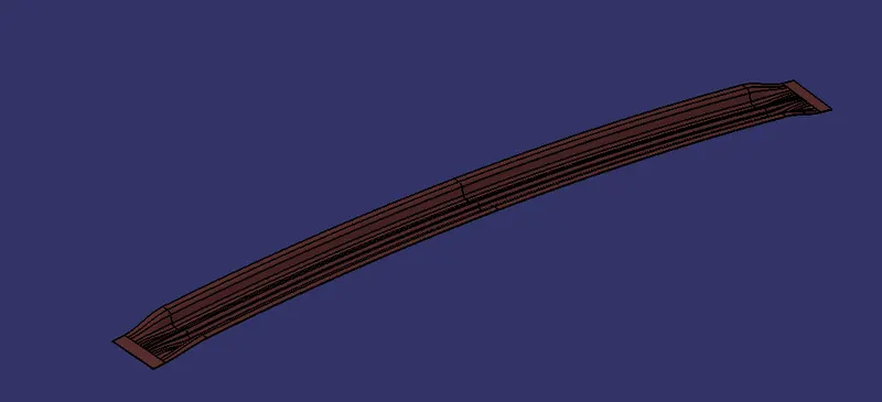
WITH REINFORCEMENT
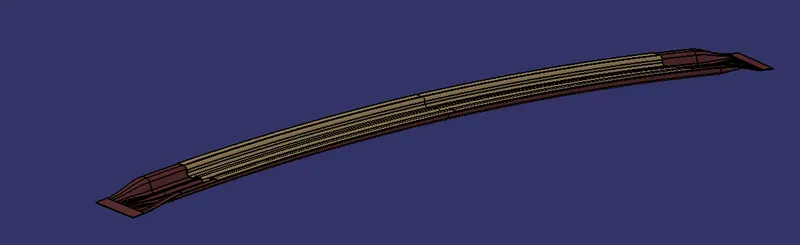
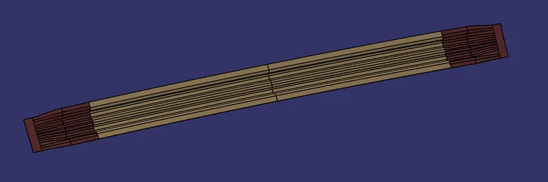
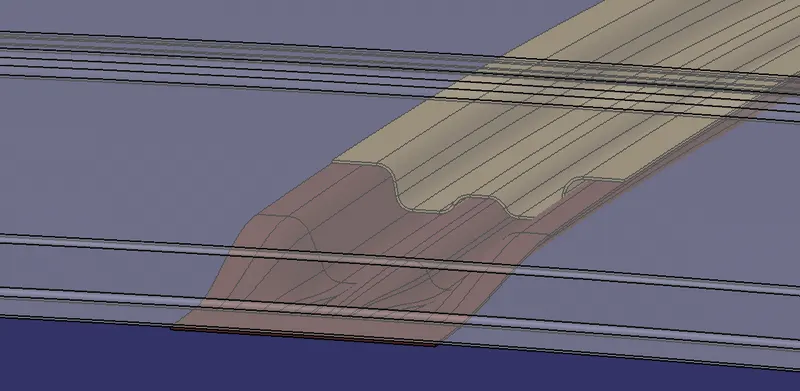
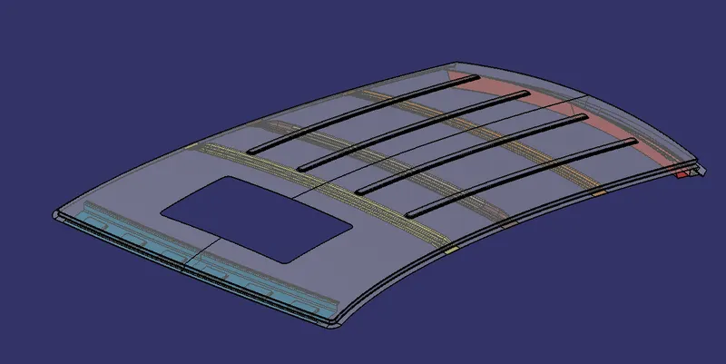
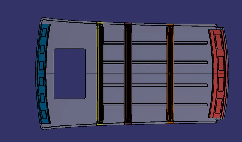
ASSEMBLY
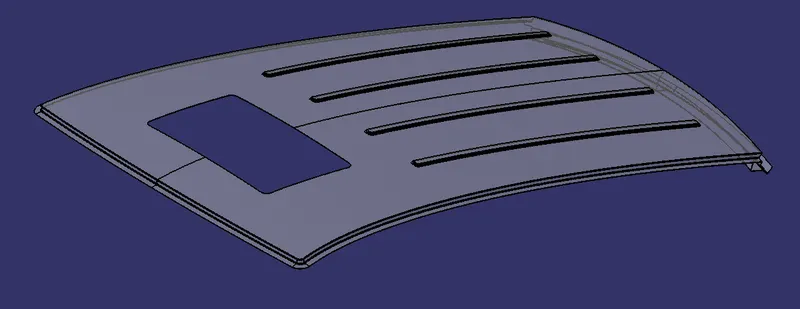
PERFORMING CURVATURE ANALYSIS
HEAT DISTROTION CALCULATION
- The temperature at which materials soften and deforms under a specific load is known as heat distrotion temperature. This study is used to predict the heat distortion temperature at where the materials start to soften when exposed to a fixed load at elevated temperature.
- In order to avoid bending or damages on the roof, based on heat distortion temperature, this study will predict the bow roof position which help to strengthen the roof.
Bow–roof prediction Formula
W = [1.73 x 10^(-3) x L] + [1.85 x 10^(-8) x (R^2)/t] + [ 1.10x10^(-3) x l] - 2.68
Judgement Condition : OK< 2.7
Where,
- L = Roof Length in X-Direction [mm] (Roof dimension in 0-Y)
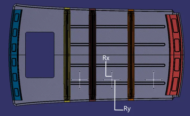
- R = Roof curvature = 2(Rx*Ry)/(Rx+Ry)
- Rx = X-curvature
- Ry = Y-curvature
- t = Roof plate thickness [mm]
- l = Bow Roof span [mm]
Steps for calculating heat distrotion,
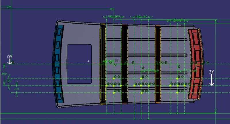
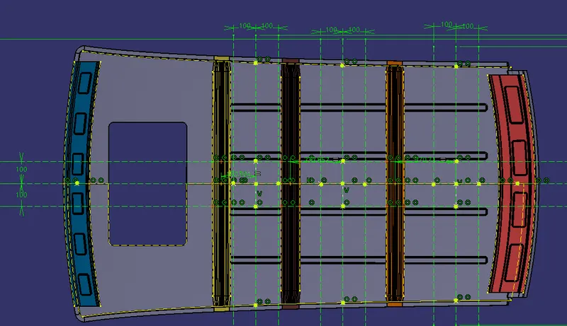
- First, open a sketch using the top datam plane and draw a line at the center of the roof. Mark the line as 0Y.
- Then, offset that line to the distance of 300 mm which is our 3Y line.
- From this line offset the line to the distance of 100 mm above and below the 3Y line.
- Create points between the bow roof rail 1, the center roof rail, bow roof rail 2 and rear roof rail at its center and then create lines seperately passing through that points.
- After that, create the lines before and after to that intersected line at the distance of 100 mm each.Then create points on the lines which are intersecting each other.
- Project those points to the outer roof surface and draw a circle on those points using three point circle option.
- Finally, measure all the valuse which are necessary to calculate the heat distrotion.

Where,
- Case 1 is between bow roof rail 1 to center roof rail.
- Case 2 is between center roof rail to bow roof rail 2.
- Case 3 is between bow roof rail 2 to rear roof rail.
SNOW LOAD CALCULATION
- This test is much more important for a light commercial vehicle (LCV) because LCV has bigger roof area, more straight style and as a result of these two properties it has heavier roof panel than the other vehicle.
- So the roof is designed in such a way that if the snow load on the roof then it may bend but needs to be back in its original position after the removal of snow load.
Snow load Prediction formula;
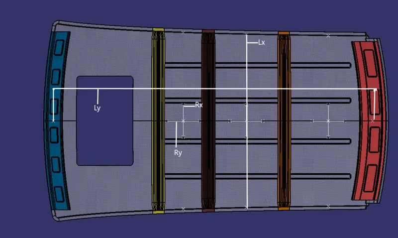
Qr = [Iy x t2] / [a x s x [(Rx + Ry)/2]2 x 10^(-8)]
Judgement condition = Qr ≥ 3.1
250 ≤ s ≤ 380
Where,
- a = My x Lx2 x 10-12 , My = Y(Ly-Y)
- t = Roof plate thickness (mm)
- Ly = Distance between the front and rear roof Rails on the Vehicle along with 0Y (mm)
- Lx = Distance between the Left and Right end of the roof on the Roof BOW (mm)
- Y = Distance front Front Roof Rail to Roof BOW (mm)
- s = Distance for which Roof BOW bears divided load (mm) , s = L1/2 + L2/2
- Iy = Geometrical moment of inertia of Roof BOW (Y cross-section ) (mm^4)
- Rx = Lateral direction curvature radius of roof panel Y cross-section on Roof BOW (mm)
- Ry = Longitudinal Direction curvature radius of the Roof panel X cross-section on Roof BOW (mm)
Steps for calculating the snow load,
- Create a line '0Y' at the center of the roof as like we did in the heat distrotion calculation.
- Offset that line to 100 mm on both sides.
- Create points between the rails at their center's. Now draw lines passing through those points and offset that line to 100 mm on both sides.
- After that, create points at the intersection on lines and measure those for calculating the snow load.
- For getting the Iy value, we need to do the section modulus for the rails.
- After getting all the value, use the formula for predicting the snow load,Qr.

LONGITITUDINAL EMBOSSES
- The longititudinal enbosses were created as the snow load calculation between the center roof rail and the bow roof rail 2 fails the judgement condition.
- These embosses provides the sufficient strength or support to the roof in any conditions.
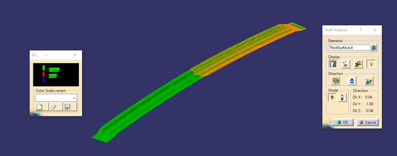
PERFORMING FEATURE DRAFT ANALYSIS
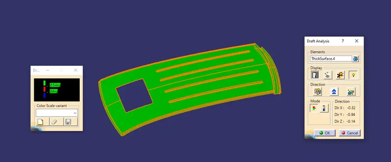
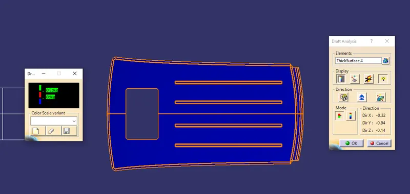
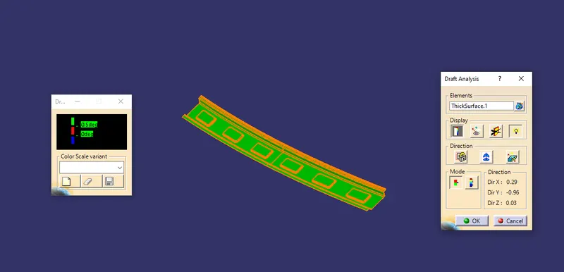
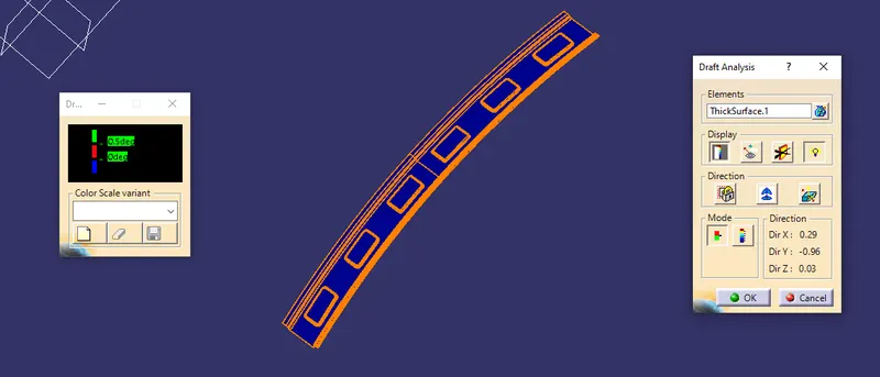
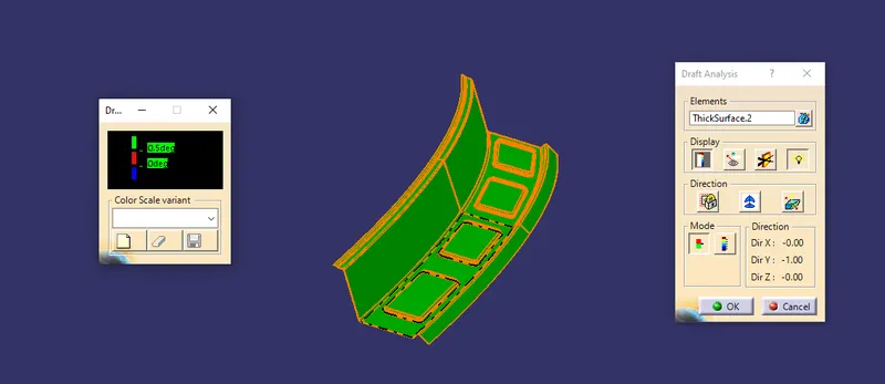
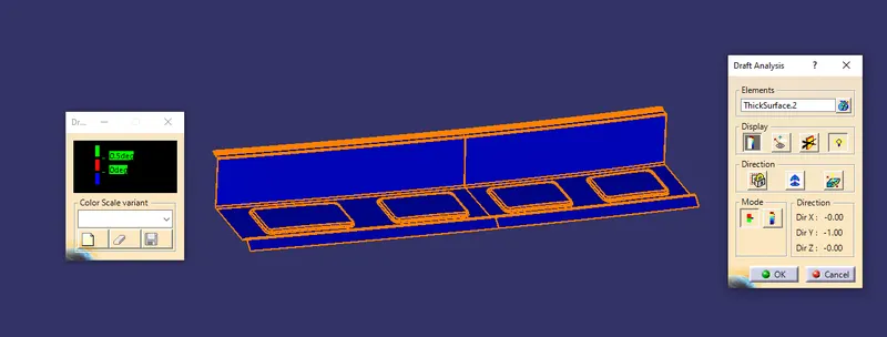
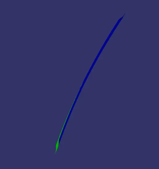
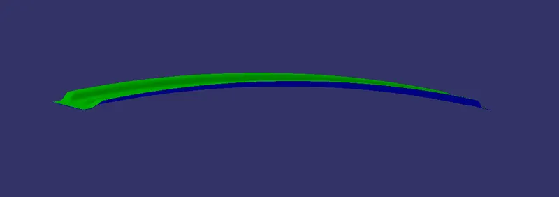
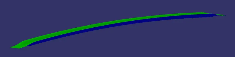
- The draft analysis was performed on each thickened surface.
- This darft anslysis is done to check the manufacturing feasibility.
ROOF OUTER
FRONT ROOF RAIL
REAR ROOF RAIL
BOW ROOFS & CENTER ROOF RAILS
CONCLUSION
- Thus the roof design with all the components (center roof, bow rails, center rail, front and rear rails) were created by following the design considerations and the given master sections.
- The curvature analysis were performed, in that the heat disrotion cleared the judgement condition but the snow load didn't clear the judgement condition.
- For that, the longititudinal embosses were created to compensate the support or structural strength for the roof.