Roof Design
Roof panel of a car definition:
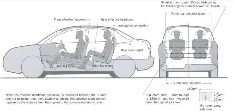
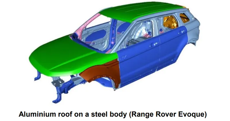
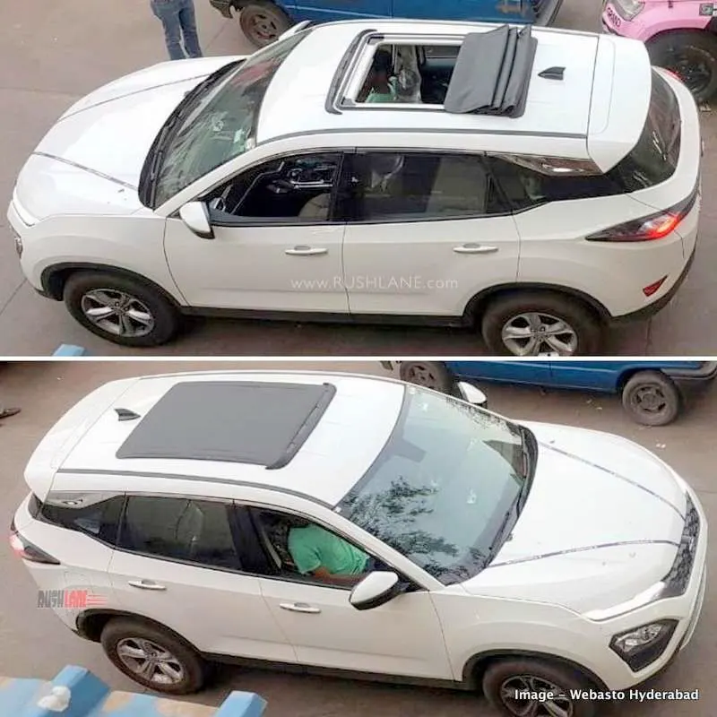
The roof panel is the section of material, usually sheet metal, that forms the roof of a vehicle. Its long, low hood was impressive, as was the flat roof panel.

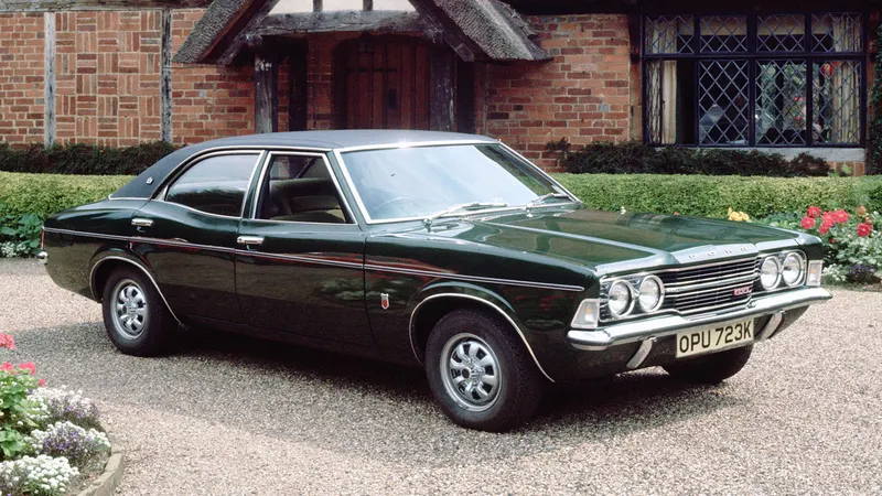
Vinyl roofs: Affordable and long-lasting roofing material, vinyl roofing systems are a magnificent choice. Vinyl roofs can last for up to 30 years and require very little maintenance. They are made to be highly resistant to chemical, environmental, and fire damage.
Normal roof with rails: Another important application of aluminum extrusions are roof rails. Roof rails are placed on the top of the vehicle and are used to carry additional luggage and equipment. Aluminum extrusions are used for manufacturing roof rails because they enable visually attractive, low weight and high strength designs.
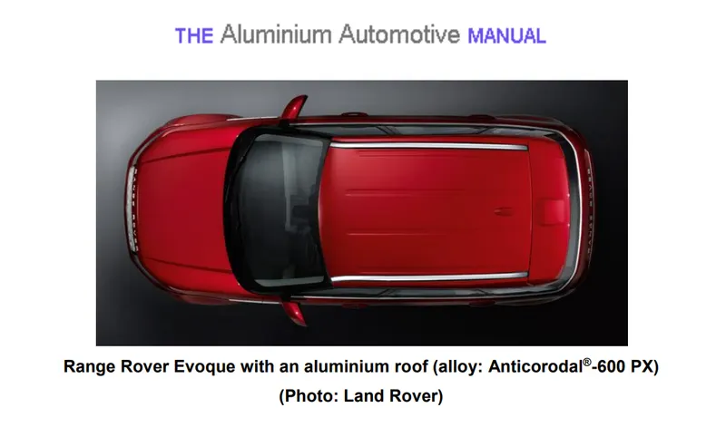
Roof Design:
Design a Roof with its components by following the master section
Initially putting all sets into a parent group:
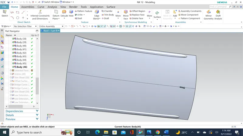
- Extracting surface using Extract geometry command.
- Using untrim command holes of rod enclosed.
- Trim excess by compare of original roof.
- Got half working area of styling section
Working on side flange based on master section:
- Off setting surface down wards around 32mm.
- Law of extension 6mm (For wind shield )
- Upper sheet working with law of extension 15 mm down ward by selecting vector to specify 3 degree.
- Again law of extension out ward distance of 21.5mm with 25 degree based on wind shield roughly
- Law extension on lower sheet about 20 mm with 25 degree out ward direction
- Thickness of our component 0.75
- Off set outer most flange of upper sheet by considering the thicken direction 0.75+0.75+0.2=1.7mm (0.75 for thickening 0.2 for mastic)
- Trim & extend in lower sheet to make corner.
- In upper sheet doing law of extension down from the flange with 15mm & 10 degree. (Minimum draft angle for sheet metal is 7mm)
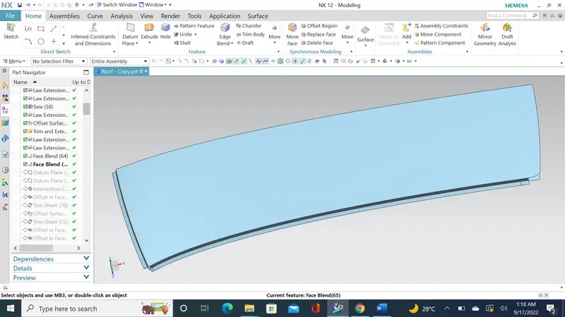
Creating front roof rail 1: ( Dimension followed as per Challenge help videos are available in the video number 20 - Help section )
- Again law of extension 20mm distance with angle of 25mm.
- Creating datum plane corner of the upper sheet
- Then creating duplicate of datum from previous datum about 80 mm
- From upper metal generated inter section of curve
- Trim sheet corresponding to inter section curve at lower sheet
- Off set upper sheet 4.7+.75x2
- Again using same boundary from upper sheet trim the lower sheet.
- From the upper sheet off set curve for 10mm and 5mm.
- Trim sheet lower sheet with above curve reference
- Again off set 2.7+0.75*2
- Trim sheet lower sheet with above curve reference
- By using through curve joining those flanges with surface from lower to upper
- Creating datum to cut the section using trim command
- Providing face blend and edge blend for those flange corners 3mm and 5mm as follows in master section
- Further providing face blend for those flange corners about 2.2mm
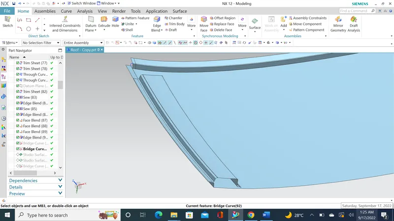
- Creating bridge curves in corner then using command called studio surface to fill with sheet
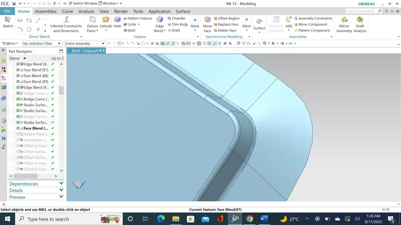
Creating bow roof rail 1: ( Dimension followed as per Challenge help videos are available in the video number 20 - Help section )
- Based upon snow load and heat dissipation
- Bow roof rail should be attached with mastic as well as side flange
- In curve creating datum plane at distance of 508 mm & creating intersection line on the roof upper surface.
- Off set curve in surface for 10mm
- Off set outer most surface sheet down wards for 0.75*2+0.2 mm
- Off set curve in surface for 15mm 20mm 25mm 35mm
- For w shape first and last 10mm & middle two side 5mm
- Providing Draft angle bottom sheet to the upper sheet
- Trimming unwanted area on both off set surface
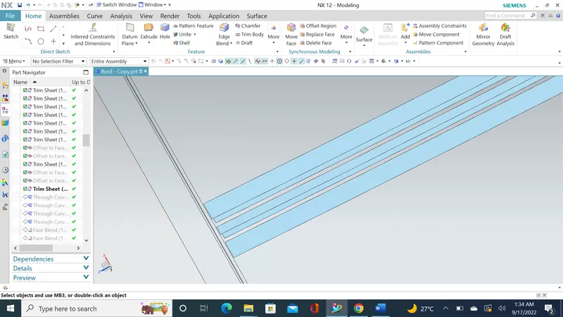
- With help of through command creating surface between two off set trimmed surface.
- Appling face blend with radius of 2.2 mm.
- Creating outer most panel side flange of off set 20mm.
- Trimming side flange using datum plane as much as require.
- Joining flange & W shape structure using bridge cure connecting two structure
- Then applying command studio curve to create surface between two structure
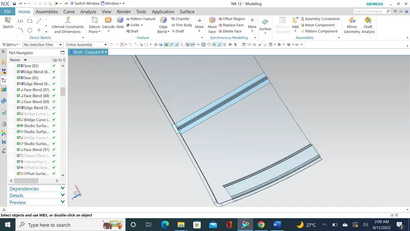
Creating center roof rail: (Challenge dimension as follows)
- Operation Similar to bow roof rail creation
- Refer command used as far as same in mentioned in bow roof rail 1
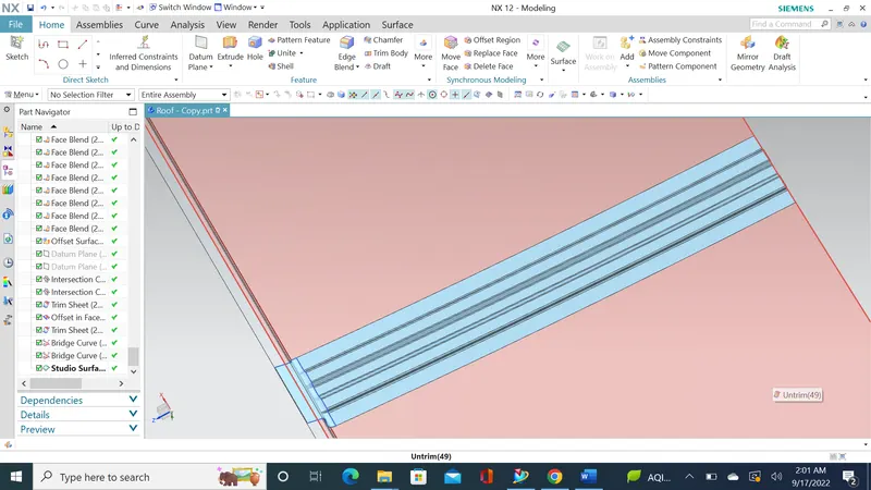
Creating bow roof rail 2: (Challenge dimension as follows)
- Operation Similar to bow roof rail creation
- Refer command used as far as same in mentioned in bow roof rail 2
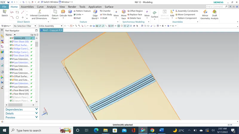
Creating rear roof rail 2: (Challenge dimension as follows)
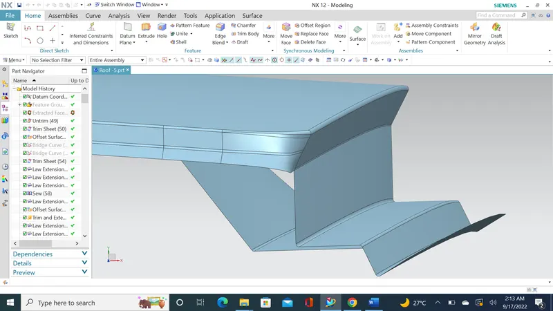
Roof assembly after thickening:
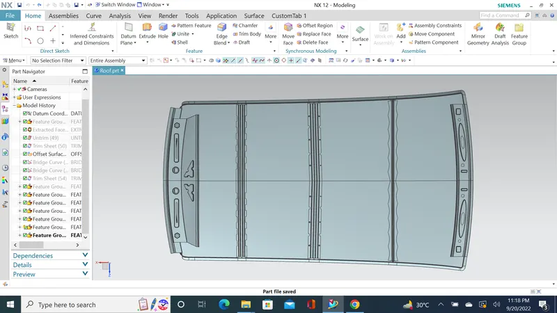
Section Modulus calculation:
Section Modulus:
Section modulus is a geometric property for a given cross-section used in the design of beams. Other geometric properties used in the design include an area for tension, radius of gyration for compression, and moment of inertia for stiffness.
Front Roof rail
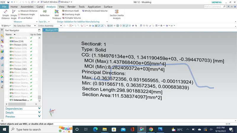
The intersection was created and then Section Inertia command was used to obtain Momentum of inertia.
Bow Roof rail 1:
The intersection was created and then Section Inertia command was used to obtain Momentum of inertia.
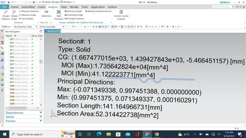
Center Roof rail:
The intersection was created and then Section Inertia command was used to obtain Momentum of inertia.
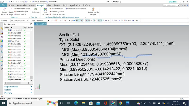
Bow Roof rail 2:
The intersection was created and then Section Inertia command was used to obtain Momentum of inertia.
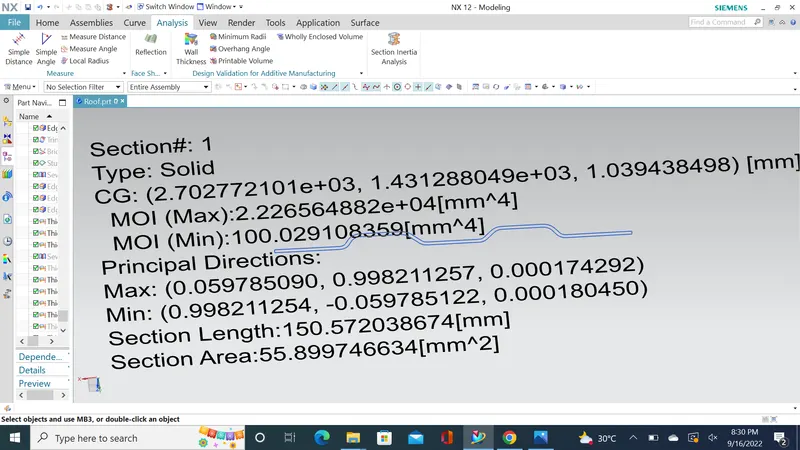
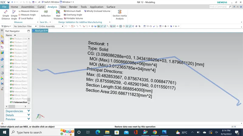
Rear Roof rail:
The intersection was created and then Section Inertia command was used to obtain Momentum of inertia.
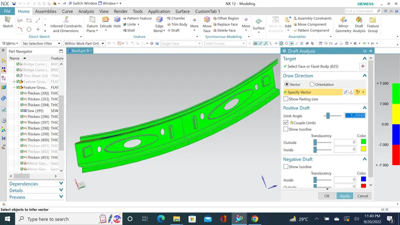
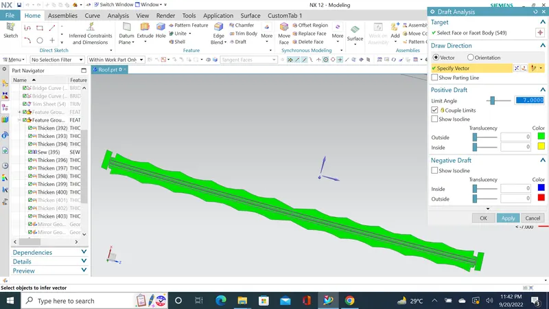
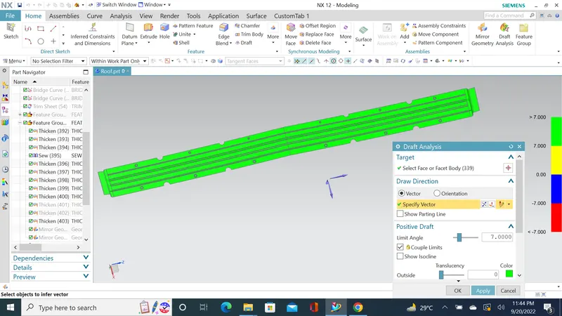
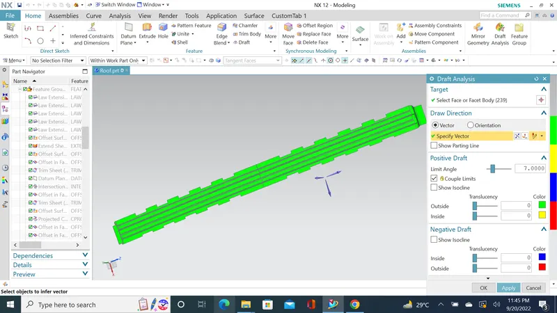
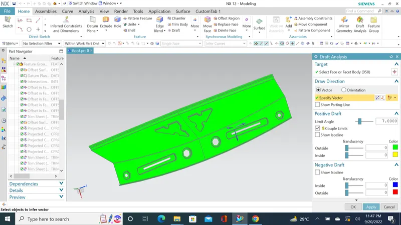
Draft Analysis
Draft analysis was performed with 7 Degrees Value (generally given in sheet metal)
Front Roof rail:
1st Bow Roof:
Center Roof rail:
2nd Bow Roof:
Rear Roof rail:
Heat Distortion study on the Roof :
The heat distortion study plays a major role in sheet metal urges. Heat distortion temperature is a temperature limit above which the material cannot be used for structural applications. This study is used to predict the heat distortions temperature at where the material starts to soften when exposed to a fixed load at an elevated temperature. To avoid bending or damage to the roof, based on the heat distortion temperature, this study will predict the bow roof position which helps to strengthen the roof.
We have a data to calculate:
W = [1.73 x 10^(-3) x L] + [1.85 x 10^(-8) x (R^2)/t] + [ 1.10x10^(-3) x l] - 2.68
Judgement Condition : OK< 2.7> 3.1
Where
L = Roof Length in X-Direction[mm](Roof dimension in 0-Y)
R = Roof curvature
R = 2(Rx*Ry)/(Rx+Ry)
Rx = X curvature
Ry = Y curvature
t = Roof plate thickness [mm]
l = Bow Roof Span [mm]
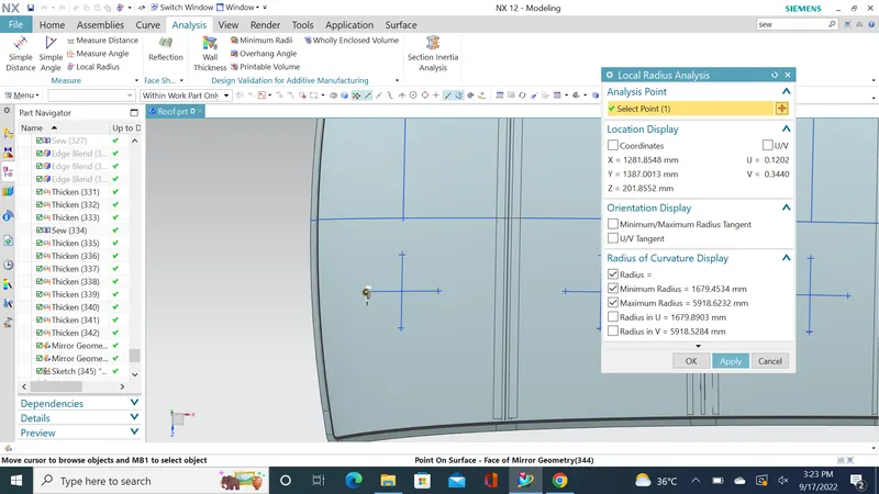
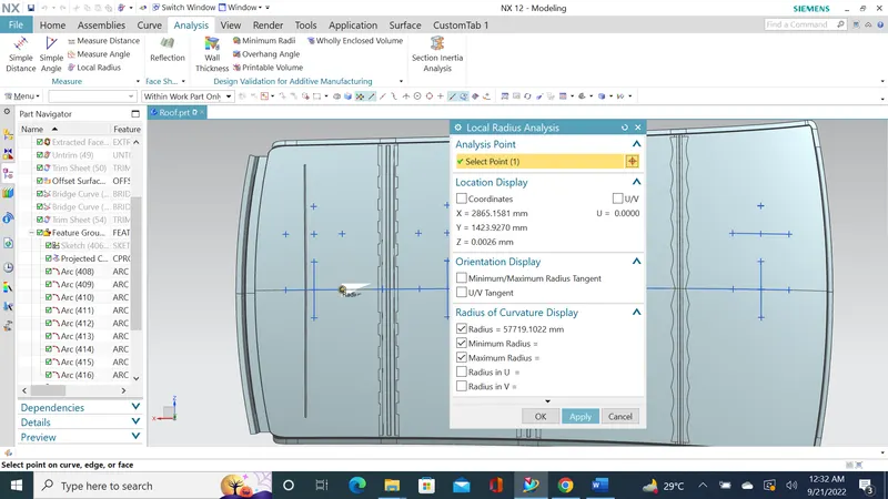
Here we have to find out the RX and Ry values. To find that:
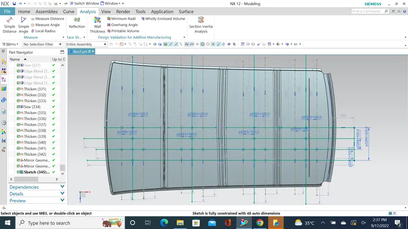
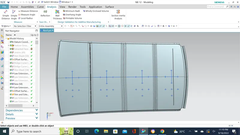
- Create a sketh on top roof and drawn a horizontal line at the centre.
- Then offset this line below 300mm and called it as -3Y line.
- From the _3Y line offset 100 mm above and below and convert all these line into refernece lines.
- Draw the verical lines at the middle of the each reinforcemnts and offset it to 100 mm both sides.
- Intersection point is created where the lines are met.
- Project these points to the outer roof panel.
| SNO | BOW ROOF | RX | RY | R | T | I |
L |
R2/T | W | RESULT |
| 1 | FRONT ROOF - BOW ROOF 1 | 2276.6 | 1679.45 | 1932.9 | 0.75 | 405.2 | 2117.08 | 4,981,469.8 | 1.52 | OK |
| 2 | BOW ROOF 1 - CENTER ROOF | 5755.2 | 5298.8 | 5517.5 | 0.75 | 450.2 | 2117.08 | 37,436,375.2 | 2.17 | OK |
| 3 | CENTER ROOF - BOW ROOF 2 | 4023.8 | 4131.1 | 4076.7 | 0.75 | 432.4 | 2117.08 | 16,619,482.8 | 1.76 | OK |
| 4 | BOW ROOF 2 - REAR ROOF | 3290.9 | 3350.8 | 3320.5 | 0.75 | 253.9 | 2117.08 | 14,700,960.3 | 1.53 | OK |
SNOW LOAD
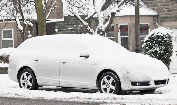
Snow load is the downward force on a car's roof by the weight of accumulated snow and ice. The roof can fail if the snow load exceeds the weight the roof was designed to shoulder Or if the roof was poorly designed or constructed.
In the winter season, in some countries there will be a huge load of snow on the roof top of the car. Snow load criteria study is done to check the ability of the roof to withstand snowfall and bounce back to its original shape without a permanent deformation once the load is removed.
So there is a formula to predict the strength of the roof.
Qr = [Iy x t2] / [α x s x [(Rx + Ry)/2]2 x 10-8]
Where
α = My x Lx2 x 10-12 , My = Y(Ly-Y)
Judgement condition = Qr ≥ 3.1
250 ≤ s ≤ 380
t = Roof plate thickness [mm]
Ly = Distance between the front and rear roof Rails on the Vehicle along with 0Y[mm]
Length of Roof panel with the center point between Roof rail Front /Rear as the front and rear reference point.
Lx = Distance between the Left and Right end of the roof on the Roof BOW [mm]
Width of the roof panel exposed on the surface.
Y = Distance front Front Roof Rail to Roof BOW[mm]
s = Distance for which Roof BOW bears divided load [mm]
s = L1/2 + L2/2
Iy = Geometrical moment of inertia of Roof BOW (Y cross-section )[mm4]
Rx = Lateral direction curvature radius of roof panel Y cross-section on Roof BOW [mm]
Roof panel curvature Radius of the Length Lx in Front view
Ry = Longitudinal Direction curvature radius of the Roof panel X cross-section on Roof BOW [mm]
Roof panel X curvature radius of length s in Side view
| SNO | BOW ROOF | RX | RY | LX | LY | Y |
IY (MM)4 |
S | My | t | ALPHA | Qr |
| 1 | FRONT ROOF - BOW ROOF 1 | 7494.8 | 2924.0 | 1085.7 | 2117.08 | 523.2 | 8.28 | 488 | 833876.6 | 0.75 | 0.982 | 0.0357 |
| 2 | BOW ROOF 1 - CENTER ROOF | 3773.3 | 4277.9 | 1068.7 | 2117.08 | 514.6 | 41.12 | 524 | 824595.0 | 0.75 | 0.941 | 0.2892 |
| 3 | CENTER ROOF - BOW ROOF 2 | 2621.7 | 15214.3 | 1085.7 | 2117.08 | 518.0 | 100.02 | 511 | 828323.4 | 0.75 | 0.976 | 0.1417 |
| 4 | BOW ROOF 2 - REAR ROOF | 3800.6 | 57719 | 1085.4 | 2117.08 | 517.2 | 3.01 | 412 | 827457.9 | 0.75 | 0.974 | 0.0004 |
Conclusion-
- We have successfully designed Ditch area flanges, Front roof rail, Bow roof rails, Center roof rail & Rear roof rail as per the requirement.
- As per heat distortion criteria we come to know all bow roof positions are OK.
- As per Snow load criteria we come to know there is improvement required.
- All roof rails draft analysis are found OK.