Roof Design
Aim:
Design a Car Roof with its components by following the master section of the front roof rail (Front roof rail, bow roofs, center roof rail and rear roof rail) with all the design parameter.
Abstract:
Safety point of view vehicle roof plays very crucial role specially roll over kind of accidents, in which vehicle tips over onto its side of roof. And vehicle rollover crashes are the causes of many fatalities and several head, neck and spine trauma around the world. Therefore passenger safety is also very important parameter in front of OEM’s. It is not onl a marketing strategy but also it is a obligation stipulated by international standards that are now place in several countries, as well as a governmental requirement. For this reason strength is very important criteria for designing vehicle roof.
Standard experiment setup:
The strength of the roof structure to occupant protection in real world rollover crashes, requiring the maximum moving distance of the roof structure should be less than 127 mm (5 in.) when the induced load is 1.5 times of the vehicle weight. For the test the passenger car shall be rigidly placed or positioned on a horizontal surface with the doors locked and the window closed. Furthermore, a flat, rigid block with lower surface a rectangle measuring 30 inches wide by 72 inches long (762mm X 1829mm) shall not move more than 5 inches(127mm),measured as the distance between the original location of the lower surface of the test device and its location as the specified force level is reached, when it is used to apply a force of 1.5 times the unloaded vehicle weight(UVW) or 5000 lbs(22224N),whichever is less ,to either side or forward edge of the vehicle. This test can be conducted on either side of the roof structure, the front left or the front right side but not on both sides in one single test and still meet the requirements of the test .
Roof Assembly
The conventional task of the roof panel is that of compartment shielding, passenger protection and connection of body sides, front and roof cross members. In case of roll over, compartment integrity is provided by the compartment frames, whilst the roof target is only to avoid the ejection of passengers, providing protection against hard local contact.
Correspondingly a wide selection of suitable materials are available: Steel, aluminium, thermosetting plastic sheet, glass. In case of steel grade FEP04, the usual thickness is in the range of 0.65 to .85 mm. In all cases, any roof panel material requires braces to prevent panel flexing and vertical waviness, commonly known as oil canning: for this purpose light steel bows are introduced, which are welded or riveted or screwed to the body side and bounded to roof panel by smooth flexible adhesives such as butyl mastic (in order to avoid sink marks on roof surface), mainly providing a damping effect.
Another task of roof bows is to support the interior roof liner which requires a number of fittings both in central and boundary areas to avoid deflections and vibrations. Fittings are usually plastic clips or velcro strips. Some roof liners, mostly on less expensive vehicles are bonded directly to roof panel.
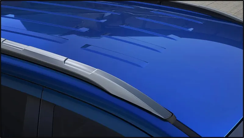
Design of Roof includes:
- Ditch area
- Front roof rail
- Rear roof rail
- Bow roof( 1,2)
- Centre bow roof rail
Design Concept sheet:
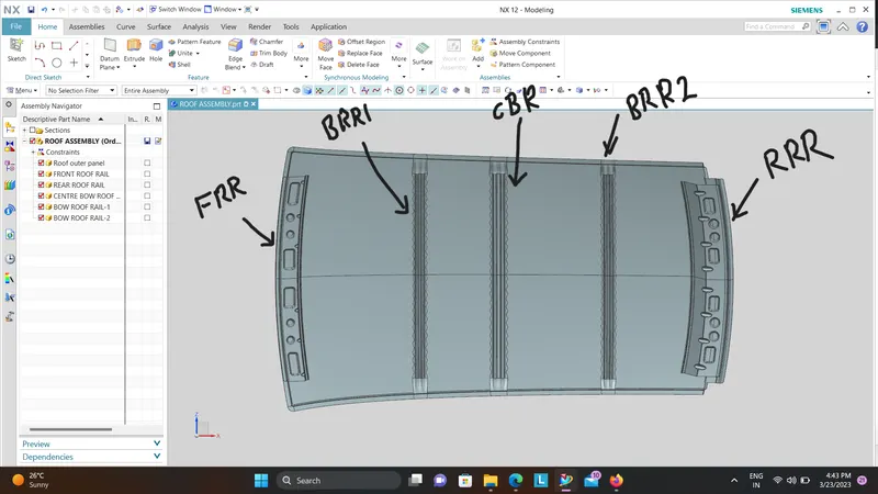
.
Materials used:
Steel is the most used of the materials, making it less expensive and affordable as a metal roofing option for homeowners as well as commercial builds. Tin had its day, but now often refers to galvanized steel when spoken about in terms of roofing.
5 Types of Metal Roofing
- Copper - Extremely long-lasting, very soft with low melting temperature
- Aluminum - Long-lasting, resistant to salt water corrosion
- Zinc - Extremely long-lasting, resistant to corrosion and lowest melting point
- Steel - Three variations: galvanized, galvalume, and weathering steel (corten)
- Tin - Often referring to steel, used prior to World War II. No longer commonly applied.
Objectives:
The main objective of this project is to come up with a new design for CAR ROOF from styling surfaces that satisfies,
- The design requirements for the roof and its components.
- Functional requirements.
- Roll over test regulations & requirements.
- Bow Roof position justification.
- Joining techniques like welding and mastics.
Design of Roof and Optimization:
It is the outer surface designed by the styling team for the aesthetics of the vehicle, the BIW team design the way of mounting on the vehicle by considering the necessary reinforcement to support the structure. The reinforcements are designed by considering the necessary load conditions.Designer alos should create the Ditch area in order totaken into account the fixation of the mating BIW Components adjacent to it.First thing to consider while designing the roof is the opening angle, of the flanges such that there is no negative draft.If the roof rail is flat it is weak and if it is tilted or curved then it has more strength.As the roof is large so to increase the strength of the roof where it appears flat due to its long distance Roof Bow are given to increase the strength of the roof.Since the roof has numerous functions so the roof has to be stronger enough to withstand the damage experienced by it. To have good strength and stiffness, the Roof consists of components:
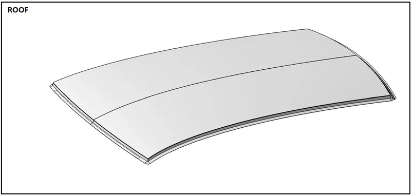
1.Front roof rail &Rear roof rail
- The Rear roof rail has joints with the backdoor, bodyside outer where as the Front roof rail has joints with windshield glass, bodyside outer and inner panels.
- From the ergonomics team we get to know where the front driver is sitting, hence there should be minimum head clearance.
- There should be clearance of 5-10mm b/w headliner and BIW.
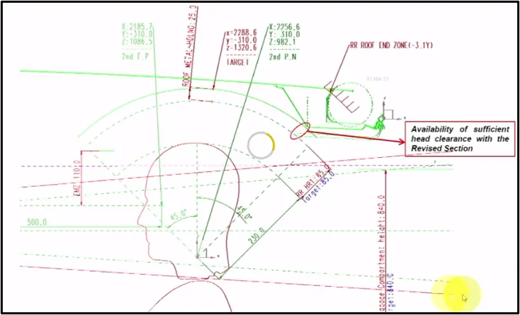
- There should be clearance of 85mm b/w rear roof rail plus headliner and the passenger.
Typical Section-Fr Roof Rail
Front roof rail is the additional commodity attached to the roof which gives the reinforcement and also having the certain features in it which helps in attaching the Bracket map lamp and the room lamp which will be mounted on this rail.
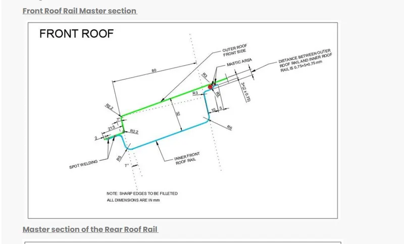
With respect to the above master section received fromm the styling team,we have designed the Fr Roof rail considering all the design parameters is shown below:
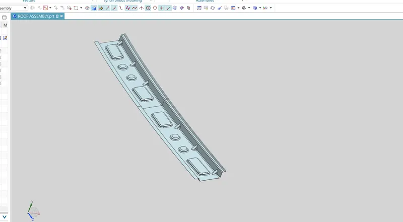
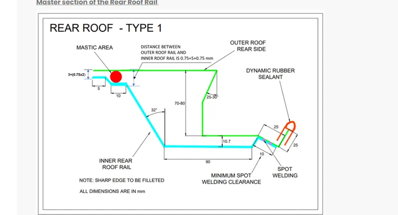
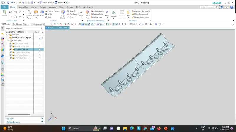
Typical Section-RR Roof Rail Lower
While designing the rear roof rail lower,we need to consider the condition of rear head room clearance and the rear visisbility criteria.
Head room clearance and field rear Vision
2.Bow roof
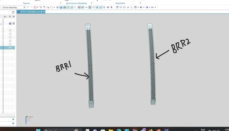
- Mastics are applied between roof and the roof rail and bow roof. When the mastic gooses out it joins the roof rail, bow roof with the Roof.
- As we have curvature in front and more flat in the back side of the roof, it is sufficient to have reinforcement centre alone in front and both the roof bows behind.
- If the roof was small with better curvature we use only one centre reinforcement roof rail which also acts as the roof bow.
- Number of bow roof increases if the car size becomes longer and taller. More taller car means more flat region means more Bow roofs.
- If the styling surface does not with stand the Heat Distortion criteria and snow load condition or the strength of the roof is less then in styling surface modify the radius of curvature of the roof and send it to the styling team if they accept it then proceed.
- So as to propose a value of that curvature radius will have to do trial error for the values of Rx and Ry.
- Always gradually increase the curvature radius not drastically.
- If the styling team does not accept the change in radius of curvature of the surface then embossing is done on the roof of different shapes so as to increase the strength of the roof.
- Always place Roof Bows on the flat region and not on the curvature region.
- Also there is a bracket placed on the reinforcement centre so as to mount the room lamp in the car.
Load Cases:
The primary functional requirements for the roof and roof structure are to:
• Provide protection for the occupants from the elements
• Meet federal roof crush regulations (FMVSS 216)
• Contribute to the structural performance of the body
• Contribute to maintaining the dimensional accuracy of the body
Based on the roof structure’s functional requirement, the CALM team selected the following load cases to study for this project:
1. Roof Crush.
2. Roof Panel Dent.
3. Body-in-White (BIW) bending stiffness and frequency.
4. BIW torsional stiffness and frequency.
It was recommended by the CAR’s Technical Advisory Council (TAC) and few automakers that side impact is an important functional
requirement affected by the roof structure. CAR will study this requirement in future projects.
JOINING PROCESS :
Mastics are introduced between the roof outer panel and the reinforcements for joining . where ever the mastic are introduced there is remarkable improve of the strength
Spot welding is also introduced to join the reinforcements and the outer panel
DESIGN CONSIDERATIONS FOR A ROOF :
- Visibility criteria
- Head clearance
- Curvature study
- Heat distortion and snow load criteria
- Draft analysis
ROOF CRUSH TEST :
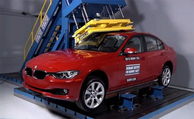
Roof crush test is the design given by the IIHS ( insurance institute of highway safety ) . After analyzing the many accidents IIHS has then fixed some regulations , that how to perform the crush test .
IIHS gives the rating based up on this test . For this they consider two points while giving the rating
- How fast the car can reforms to its original shape after the roll over and
- How deep is the protrusion after the roll over
GOAL OF ROOF CRUSH TEST :
To minimize the protrusion into the occupant compartment , so that the seat belts and air bags can do there job in protecting the occupant
CONDITIONS TO FOLLOW FOR ROOF CRUSH TEST :
There are two conditions that should be followed for the roof crush test , they are
INITIAL CONDITION :
- Close and lock all the doors
- Close all the windows
SECOND CONDITION :
Fix the body sill or chassis frame on a hard lever surface horizontally
METHOD OF APPLYING THE FORCE :
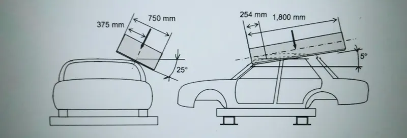
The load is applied in such a way that 50 is tilted from the front end to the rear end and the load will be in 1800 mm in length and 750 mm in width . The load is applied at the position of 250 from the flatness of the roof . The load is applied on the roof for almost 120 sec and the crush speed at which the load applied is 13 mm/sec or less than that
RESULTS :
If the displacements goes above the requirements level then we have to increase the bow roof thickness or add more mastics points to increase the strength . the stronger the roof the better it can protect the occupants in the roll over crashes.
Draft Analysis:
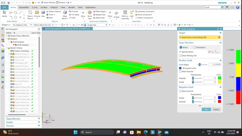
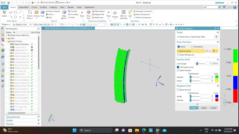
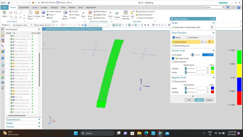
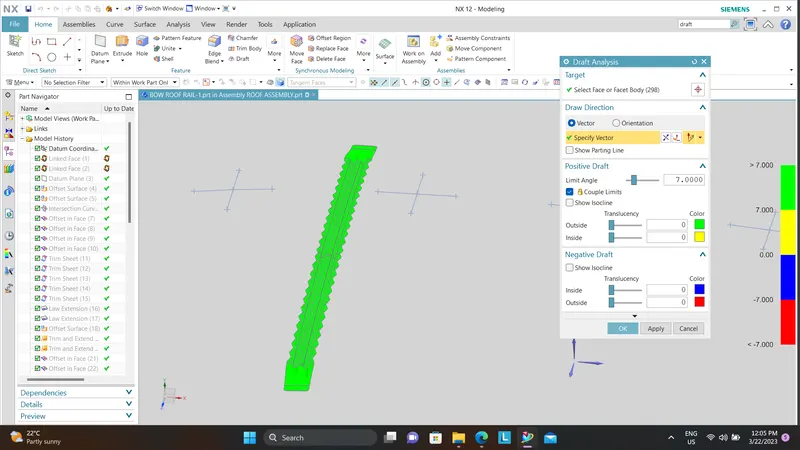
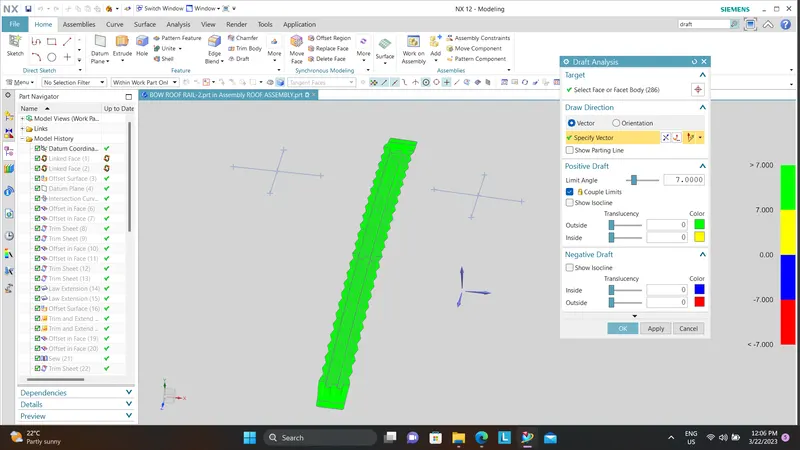
Parts Cannot be ejected from the tool if it is at 90 degree surface.for the reason,A small Draft angle is to be provide for each and every surfacs of the Component in order to easy removal of component from the moulds without any defects.Draft is the angle in which the part is tapered to allow it to release.Most of the sheet metal part require minimum 7degree 10 degree however 7 degrees are widely accepeted in sheet metal component design.Draft Analysis is the technique used to analise weather our designed product are manufacturable with required conditions or not.Below shown image is the Draft analysis of the above designed Roof:
Heat Distortion criteria:
Predicting Heat Distortion for the roof is important since it is exposed to heat for a long time and high temperatures will affect the roof structure if the design does not
conform with the heat distortion criteria. This study helps to determine the positions of Bow roofs to provide strength to the roof to avoid bending or deformation of the
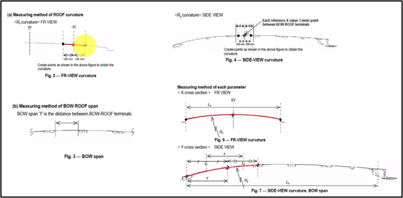
roof due to heat. Bow roof curvature study using the below formula will help us to check whether the Bow roof positions impart required strength to the roof.
W = [1.73 x 10^(-3) x L] + [1.85 x 10^(-8) x (R^2)/t] + [ 1.10x10^(-3) x l] - 2.68
Judgement Condition : OK< 2.7> 3.1
Where
L = Roof Length in X-Direction[mm](Roof dimension in 0-Y)
R = Roof curvature
R = 2(Rx*Ry)/(Rx+Ry)
Rx = X curvature
Ry = Y curvature
t = Roof plate thickness [mm]
l = Bow Roof Span [mm]
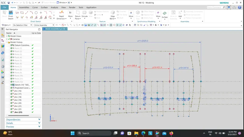

As per standards the value supposed to be lesser then the 3.1.In the Above Design,we have found the W value is lesser than 3.1 in all Components.Hence the Heat distortion criteria is satisfying.
Snow load Prediction formula:
This evalution is performed in cold regions where snow occurs.roof design must pass through these calculations to ensure that it has sufficent stiffness to withstand the load due to accomalation of snow over the roof.
Qr = [Iy x t2] / [α x s x [(Rx + Ry)/2]2 x 10-8]
Where
α = My x Lx2 x 10-12 , My = Y(Ly-Y)
Judgement condition = Qr ≥ 3.1
250 ≤ s ≤ 380
t = Roof plate thickness [mm]
Ly = Distance between the front and rear roof Rails on the Vehicle along with 0Y[mm]
Length of Roof panel with the center point between Roof rail Front /Rear as the reference point of the front and the rear.
Lx = Distance between the Left and Right end of the roof on the Roof BOW [mm]
Width of the roof panel exposed on the surface.
Y = Distance front Front Roof Rail to Roof BOW[mm]
s = Distance for which Roof BOW bears divided load [mm]
s = L1/2 + L2/2
Iy = Geometrical moment of inertia of Roof BOW (Y cross-section )[mm4]
Rx = Lateral direction curvature radius of roof panel Y cross-section on Roof BOW [mm]
Roof panel curvature Radius of the Length Lx in Front view
Ry = Longitudinal Direction curvature radius of the Roof panel X cross-section on Roof BOW [mm]
Roof panel X curvature radius of length s in Side view
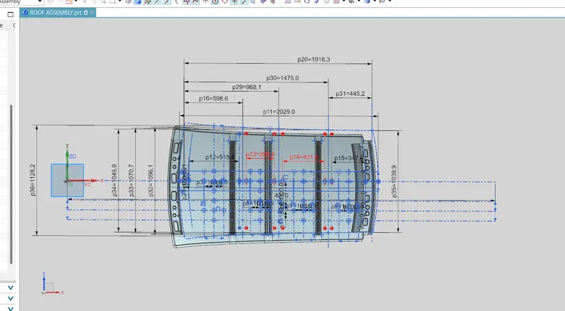

As per standards the Qr value supposed to be greater then the 3.1.In the case 1,3 snow load criteria is satisfied but in 2 case the value of qr is lesser then 3.1 so in 2 case the snow load criteria is not satisfied.for satisfying the snow load criteria we need to replace the position of bow roof1 and we can also use embosses on roof to increase strength of roof.
Conclusion:
Thus the Roof is designed and it is provided with the Front and rear rails,Bow roof and Reinforcement for the strength of the roof and also calculated the heat distortion and Snowload criterias.the Heat distortion criteria is satisfied for all the region but snow load criteria is not satisfied in case2.
Draft Analysis has been carried out provided 7 degree in order to check the maufacture feasibilty of the components.