Project 1
Aim- To route the wiring harness on given Engine and flatten view drawing in CATIA V5.
Objective- The objective of the project is to route the wiring harness on given Bugatti V16 Engine and prepare flatten view drawing in CATIA V5. All types of packaging rules have to be considered while routing the harness. Also, Industry best practices should be demonstrated in design. All the necessary details like clearance, clipping/clamping selection, harness fixing requirements, harness continuity should be provided in order to design wiring harness.
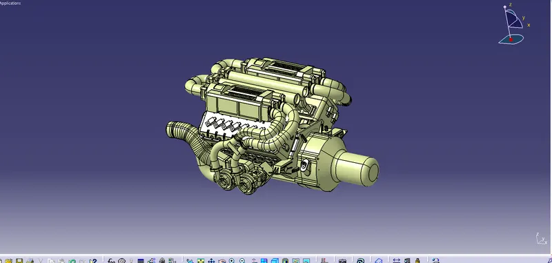
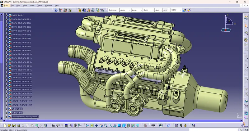
Fig. Bugatti V16 Engine
- The above figure shows the 16 valve Bugatti Engine where 8 cylinders are placed on the right side and 8 cylinders are placed on the left side.
- There are total 16 injectors where 8 injectors are used for 8 cylinders on right side and 8 injectors are used for another 8 cylinders on left side.
- Also there are 4 cam-shaft sensors, so there are total 20 sensors that we have to connected electrically.
- Generally, 4-pole connectors are used for fuel injectors of the engine.
- The engine will also have an interconnection connector which will connect the engine to other parts of the vehicle. We will be using a 12-pole electrical connector with a mounting clip feature as an interconnection connector.
- The plastic guiding channel used in this harness should bemade of a material that can withstand at least 150 degree Celcius.
- The bend ratio for the all bundle segmets should be 1.4
Assumptions-
- Provide clips/clamps as per requirement.
- Make sure that there is no any fauling case while designing the wire harness. Additional clips/clamps may be used to avoid fauling case.
- Give additional slack if needed. 5-10% slack is sufficient.
- Avoid routing over bolt and bolted joints to avoid harness puncture.
- Avoid routing on sharp edges or else provide protection over the harness.
- Follow the clearance distance and keep away the harness from heat generation components.
- Protection should be provided as needed according to surrounding temperature.
- Avoid direct support for harness on fuel lines routed in the engine.
- Use plastic guiding channels if needed.
- Branch length should be greater than 50mm.
- Minimum distance between two branch points should be at least 50mm.
- Minimum distance between clip and branch point should be at least 25mm.
- Avoid too many sheet metal brackets on the engine. Try to use available threaded bosses on the engine or demand for it.
- The wiring harness should be easy to assemble and easy to access.
- While using dummy connectors, ensure that whatever positions you are defining that are practical. Bundle diameters and another placements can be defined properly for the wire harness routing.
- If the packaging area is too tight and there are many packaging constraints then we can think of creating harness channel which can be used to route and protect the wire harness effectively.
Step 1: Creating Context Assembly
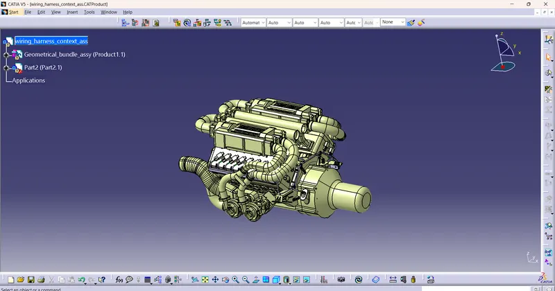
- A Context Assembly for Engine Harness has created which will work as the main assembly as shown in above figure.
- A Context Assembly will contain Engine Assembly data for Bugatti V16 Engine and Engine Harness Geometrical Bundle Assembly.
- If any sheet metal bracket will require then they are added in the context assembly.
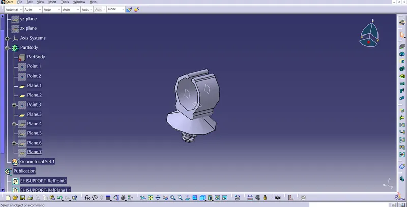
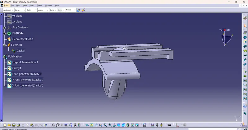
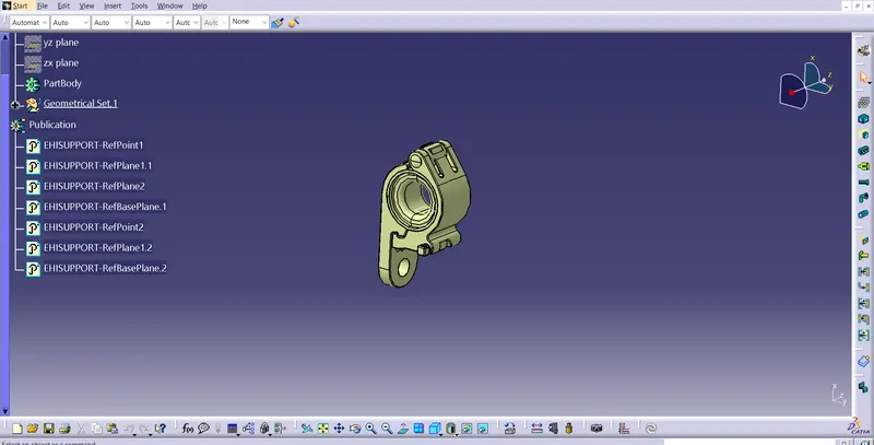
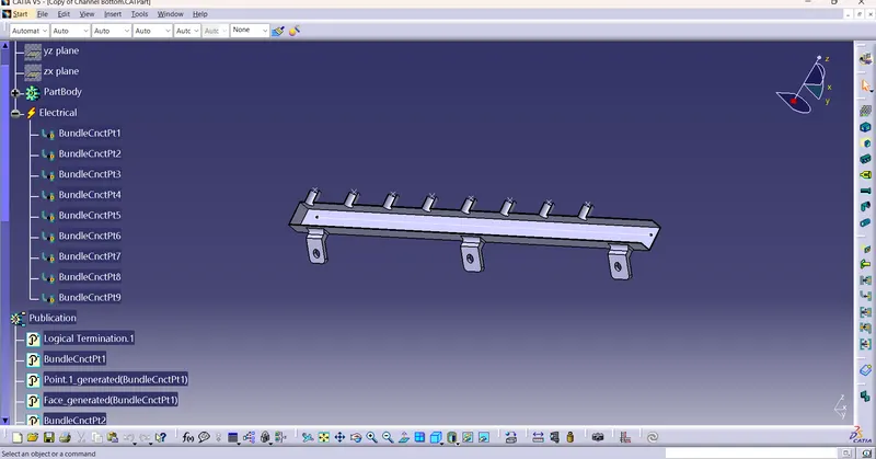
Step 2: To define all the connectors,clip&clamp and guiding channel electrically
Here,I have no data for appropirate required connectors so i used connectector as a dummy connectors. This CAD data is downloaded from te.com. Now, to define a connector electrically we should define the geometrical parameters like bundle connection point and connector connection point in Electrical Part Design workbench for the downloaded connector.
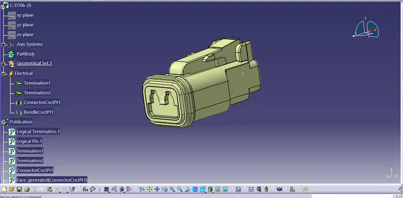
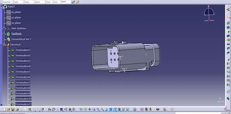
Step 3: Add required connectors,clip&clamp and guiding channel into geometrical bundle assembly
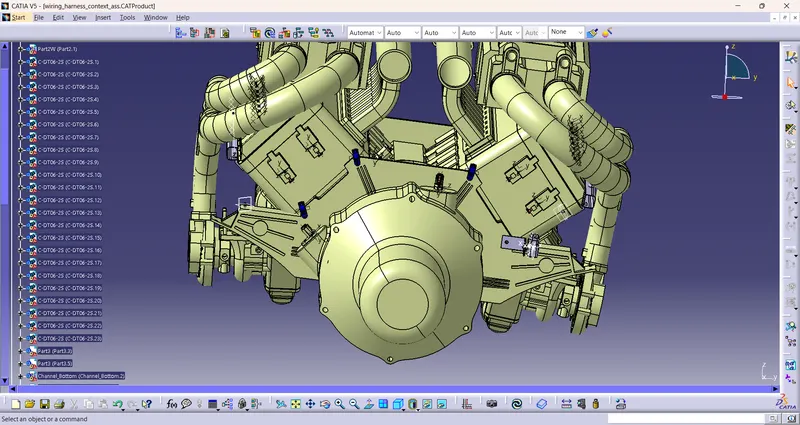
In this step, we are placing connectors to fuel injector sensors and cam-shaft sensors. So we will require total 20 connectors which have to be added in the Geometrical Bundle Assembly. We have to use manipulation tools along with compass, snap and smart move features to locate all the 20 connectors at their desired locations.
Step 4: Adding sheet metal bracket
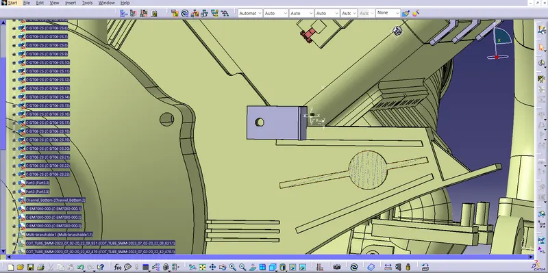
Now, we have to add sheet metal bracket in order to provide mounting for the interconnection connector. The bracket should be mounted on the existing bolt as shown below. This bracket should have locking system in clockwise direction so that it can't be move freely. Herein below figure, rib is performing the locking feature for the bracket. All the design ideas should be discussed with the engine designing team so that there won't be any disturbance for the smooth working of engine in real world application.
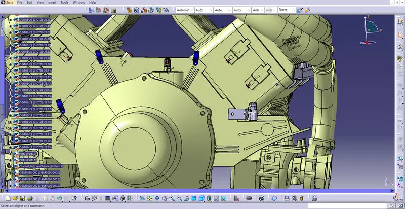
Step 5: Mounting the interconnection connector on the sheet metal bracket and mounting the p-clamps for wire harness
Step 6: Mounting of a plastic guiding channel
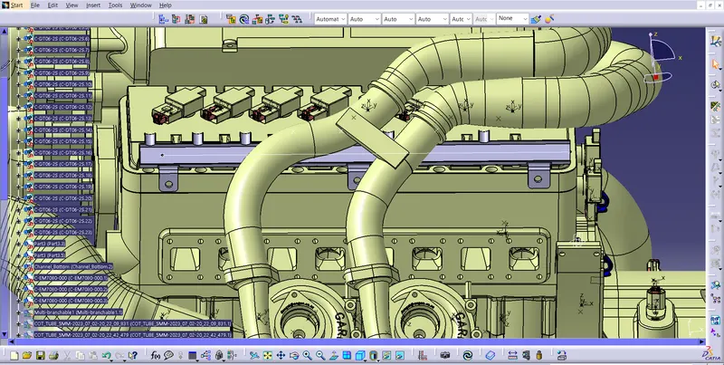
We have to add now plastic guiding channel because Bugatti V16 engine has 8 injectors on right side and 8 injectors on left side which are very close to each other. Hence plastic guiding channel is best option for proper and easy routing of the wiring harness. It will reduce the complex wiring harness routing. We will require two different guiding channel for both right and left side of the engine. Now, before placing guiding channel, we have to define geometrical parameters of guiding channel as below.
Step 7: Bundle routing from Interconnection connector to the others connectors
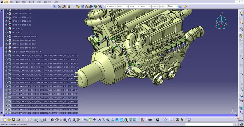
Here, we are routing the bundle segment from interconnection connector to the others connector through using p clamp,furr tree clips and guiding channel and create branching point at required places.
Step 8: Adding protective coverings and guiding channels top shell to harness bundle
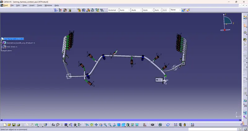
Here in below figure, we have done with whole wiring harness routing for the Bugatti V16 Engine. Now, we have to add protective coverings to all bundle segments and top shell of the guiding channel.
Step 9: Checking bundle continuity
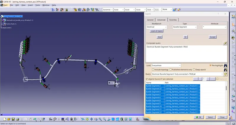
In this step, first we have to make sure that multi-branchable is selected then we have to go in Edit>Search>Advanced>Workbench-Electrical>Type-Bundle Segment>Attribute-Fully Connected
- By selecting 'True' option will show all the connected bundle segments while selecting 'False' option will show all the non-connected bundle segments.
- Here, we have selected for the 'True' option and searched for results. All the bundle segments are highlighted found showing that all the bundle segments are electrically connected as shown in below figure.
Step 10: Creating flatten view of the engine harness geometrical bundle assembly
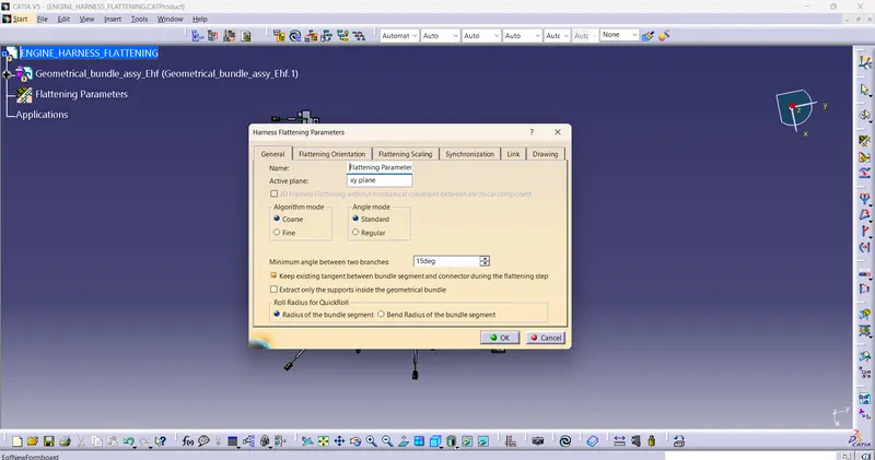
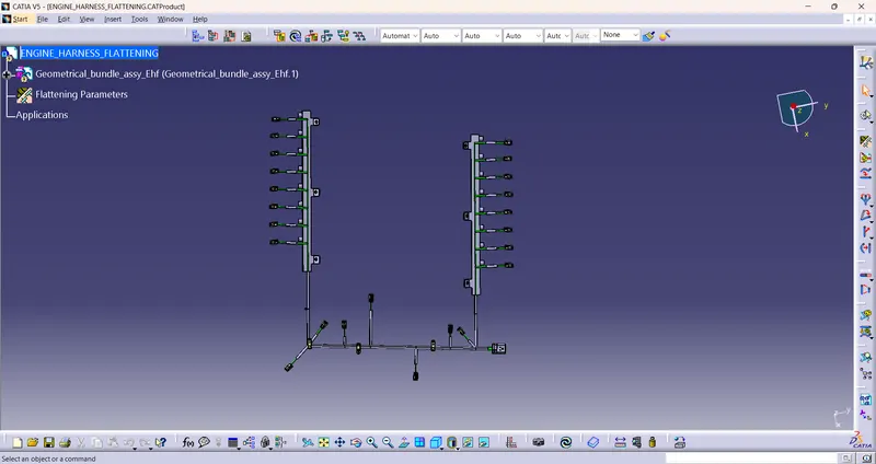
In this step, for creating flatten view we have to work in Electrical Harness Flattening workbench of Catia V5. We should also make sure that the flattening file is saved in the same folder where other files of harness assembly are saved.
Before creating flatten view, first we have to define flattening parameters.
Step11: Creating a flatten view drawing for the wiring harness assembly
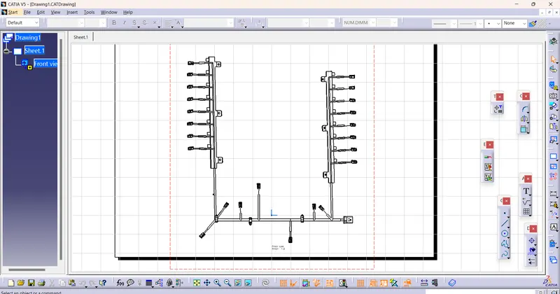
In above figure, we are creating new drawing file and defined all the necessary drawing parameters. We have to insert the front view of the Engine Harness Flattening Product file into the Drawing file.
Conclusion:
In this way, we have routed wiring harness for the Bugatti V16 Engine. Also, prepared flatten view drawing with proper sheet in CATIA V5.