Roof Design
Aim: To design the Roof as per the given master section and satisfy the prediction formulas.
Introduction:
The Roof of a car is the component that encloses the passenger compartment from the top. It protects the Passengers and the interior of the car from external environments thus providing a safe and isolated cabin. The roof plays an important role in safety, especially in the case of rollover accidents. To achieve better safety results the roof is designed with reinforcement structures such as rails.
Objective:
- To design Front Roof Rail
- To design Rear Roof Rail
- To design Centre Roof Rail
- To design Bow Roofs
- To find the Moment of Inertia in Bow Roofs
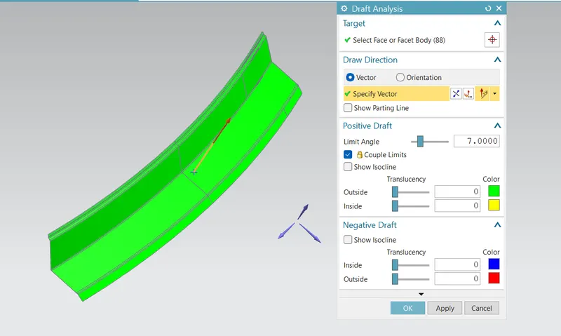
- To perform Draft analysis on all the Rails and Bow Roofs
- To check the Roof for Heat Distortion criteria
- To check the Roof for Snow Load criteria
The major components of the Roof Assembly:
- Roof.
- Front roof rail.
- Rear roof rail.
- Bow roof rails.
- Centre roof rail.
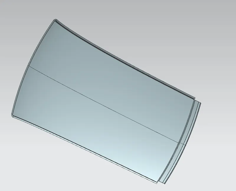
Roof:
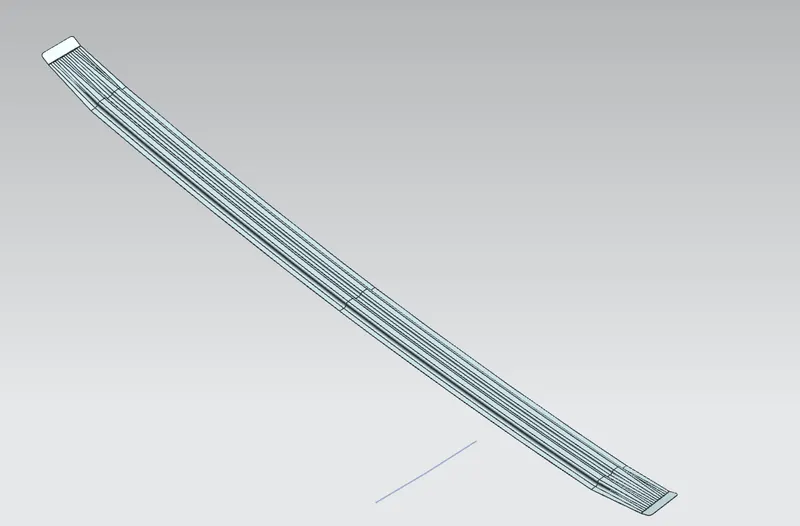
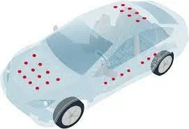
- The roof is the aesthetic part to which all the reinforcement rails get joined by spot welds at the edges and matics at the center of the roof.
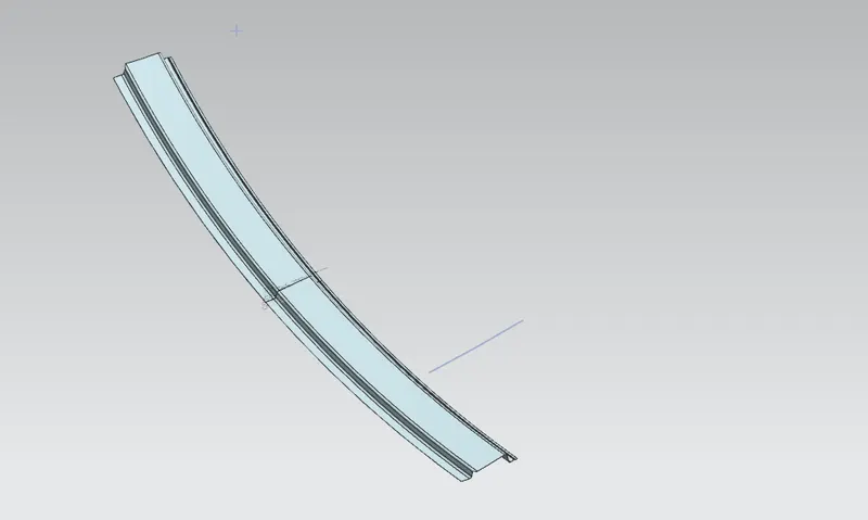
Front Roof Rail:
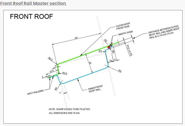
- The front roof rail is located on the front of the roof where the windshield joins with the roof. The visibility criteria and the headroom clearance of the passenger are taken into consideration for the bottom flange. The front end of the rail is joined using spot welding while the other end is joined with the roof using mastic sealants.
Rear Roof Rail:
-
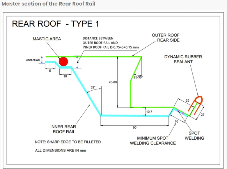
This roof rail joins with the back door and the roof. Inputs from the backdoor are taken into consideration for designing this roof rail. Here one end is joined using spot welding while the other end is joined using mastic sealants.
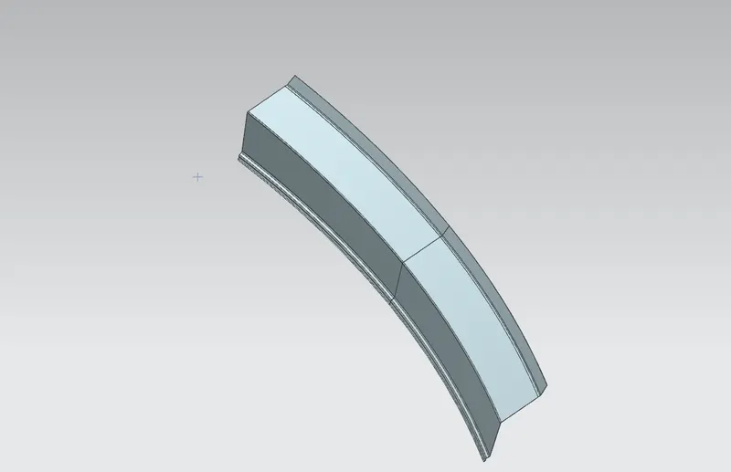
Center Roof Rail:
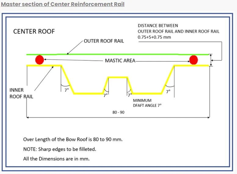
- Centre Roof rail or reinforcement center is located at the center of the roof. The cross-section of this is more since it needs to provide more strength to the roof. Here both ends are joined together using mastic sealants and the ends are spot welded with the roof.
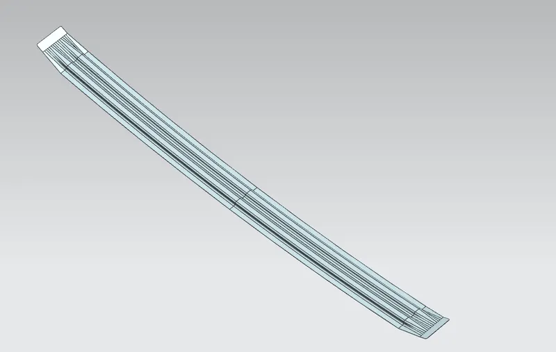
Bow Roof Rail:
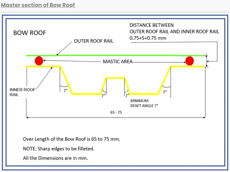
- The bow roof rails are the same as the center roof rail but a bit smaller in cross-section compared to the center rail. This rail has used to support the roof away from the center which can improve the strength. The count of these Bow roof rails depends on the Sow load criteria.
Design Consideration for the Roof Assembly:
- Frontal visibility.
- Headroom Clearance.
- Curvature study.
- Hear distortion and snow load criteria.
Design of Roof Assembly using Siemens NX:
Design Considerations:
- Clearance of 5 mm should be present between the roof and rails where mastics are used for joining.
- Thickness for all sheet metal parts - 0.75 mm.
- All edges should have fillets and there should not be any sharp edges present.
- A minimum draft of 7 degrees is required for all the faces.
- No space between the surfaces where spot weld is to be done.
Given Master sections:
Hood Assembly:
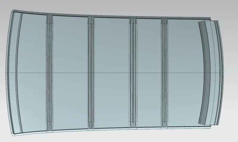
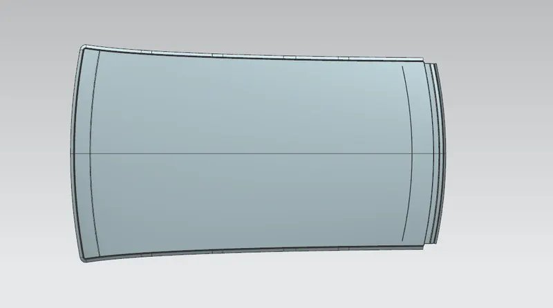
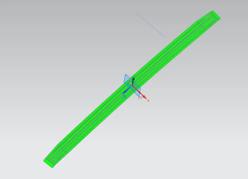
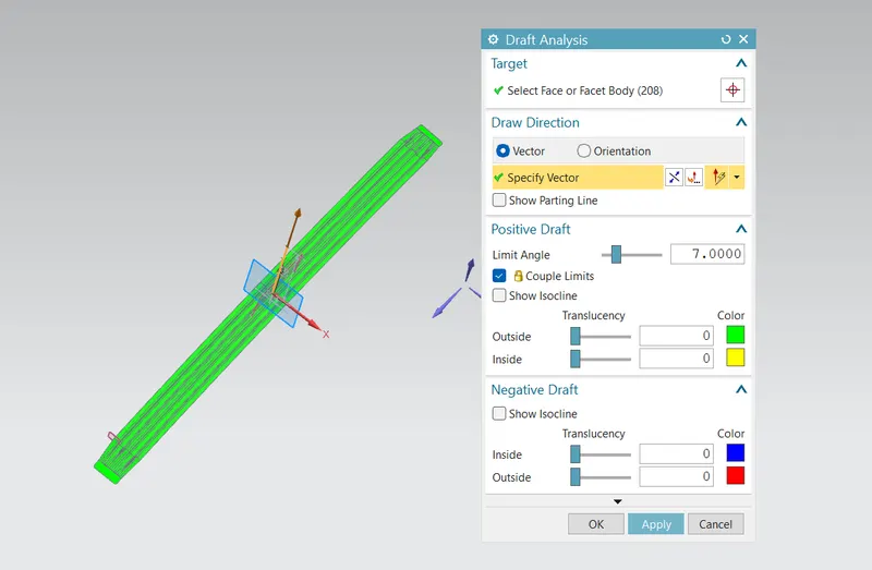
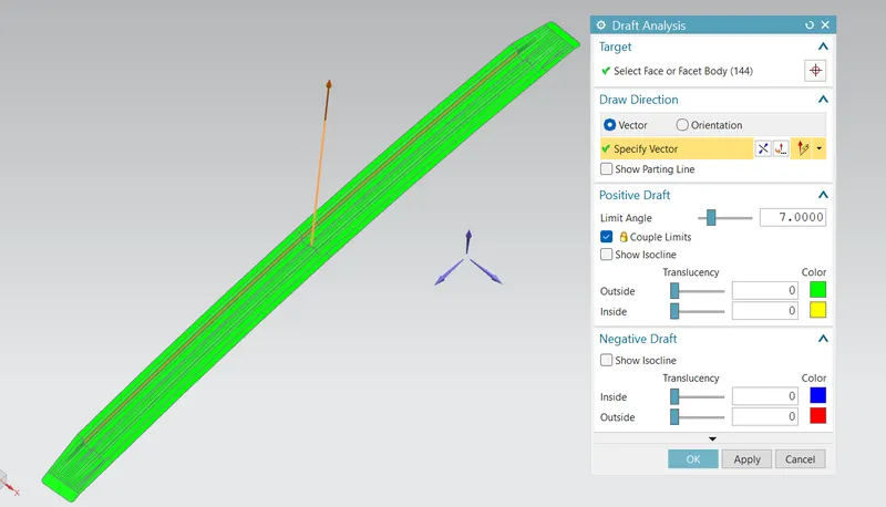
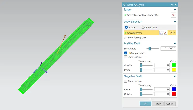
Draft Analysis:
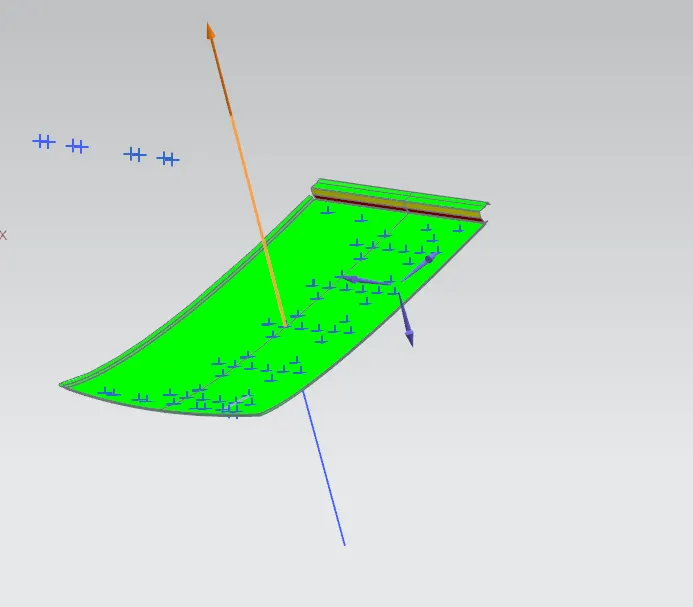
- Draft analysis is conducted to check the manufacturability(drawing operation) of the sheet metal part
- In Sheetmetal operations the minimum draft angle should be 7 degrees. If the min. a draft is not maintained the tool wear rate will increase which damages the tool, as well as the shape of the component, which also changes with time.
- Roof:
- Bow roof rail 1:
- Bow Roof rail 2:
- Bow Roof rail 3:
- Center roof rail:
- Rear roof rail:
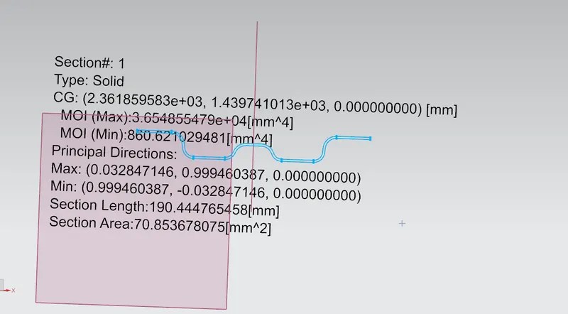
Section inertia analysis for the rails:
- Bow roof rail 1:
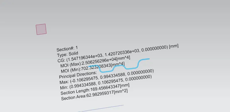
- Bow roof rail 2:
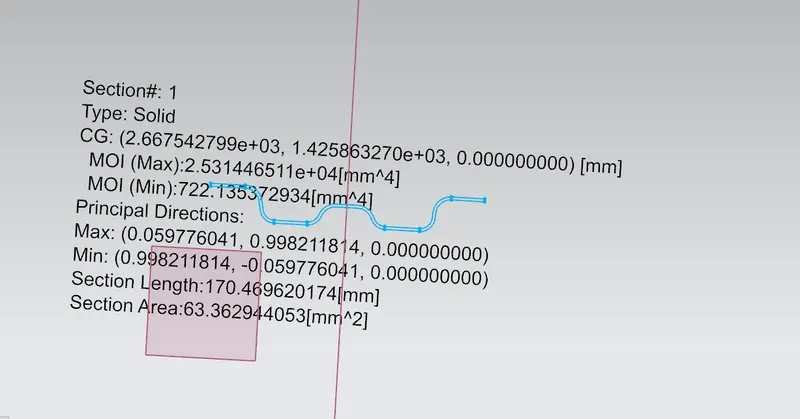
- Bow roof rail 3:
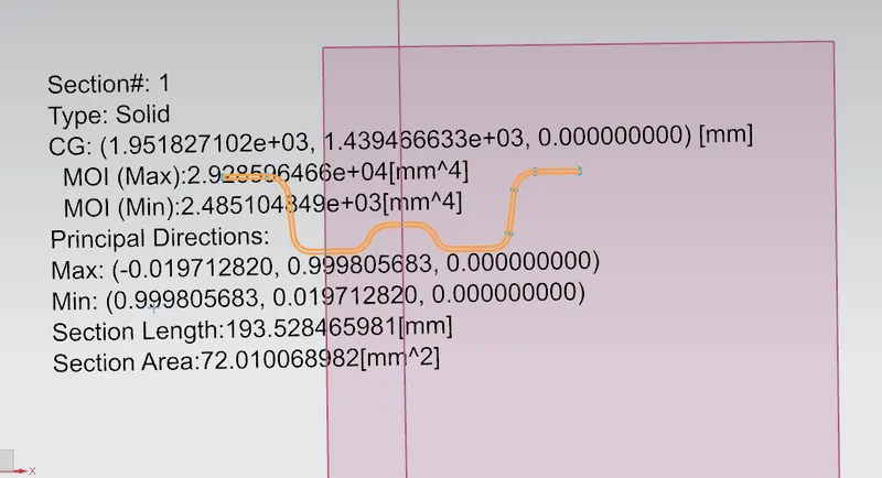
- Center roof rail:
CALCULATIONS:
Bow–Roof Prediction Formula:
- This study is conducted to calculate the heat distortion of the roof.
- Heat distortion analysis plays a pivotal role in the strength of the roof panel. It is the temperature above which material cannot be used for structural applications. This study is used to predict the heat distortion temperature where the material starts to soften when exposed to a fixed load at an elevated temperature
- W = [1.73 x 10^(-3) x L] + [1.85 x 10^(-8) x (R^2)/t] + [ 1.10x10^(-3) x l] - 2.68
- Where
- L = Roof Length in X-Direction[mm](Roof dimension in 0-Y)
- R = Roof curvature
- R = 2(Rx*Ry)/(Rx+Ry)
- Rx = X curvature
- Ry = Y curvature
- t = Roof plate thickness [mm]
- l = Bow Roof Span [mm]
- Judgment Condition
- OK< 2.7
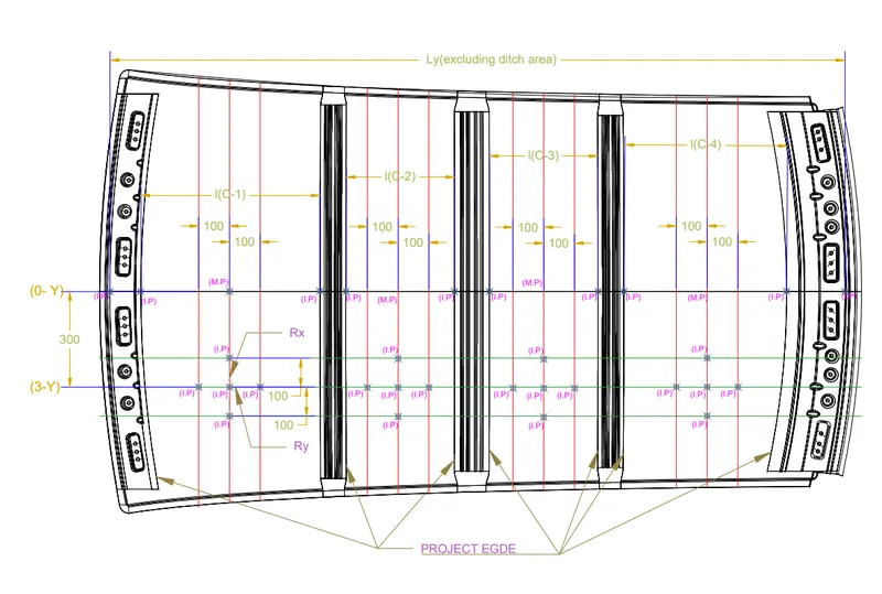

- In all cases the W value is less than 2.7 so the Heat distortion criteria is satisfied.
Snow load condition:
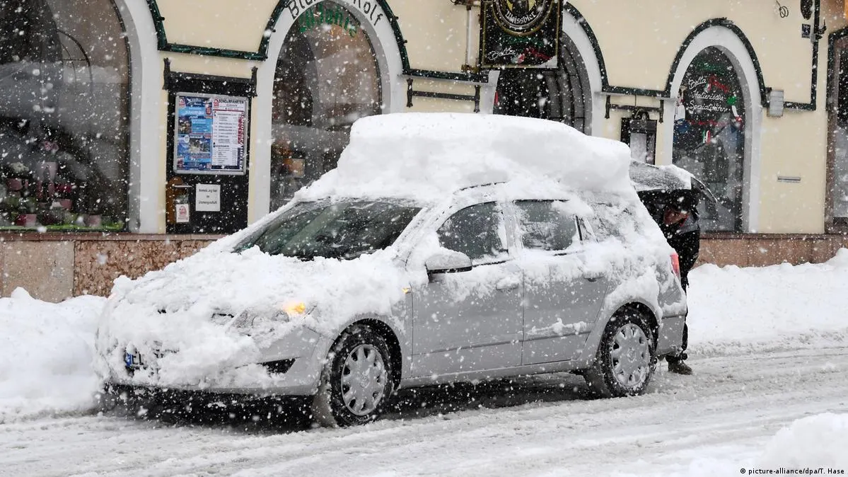
Snow load condition is not for all regions of the world but in some countries, there will be heavy snowfall where the snow gets accumulated over the roof and the roof should withstand the weight of the roof for that we have to do this prediction at the highest snow load condition.
At the highest snow load condition, the roof will form a dent over the surface and if the dent is deformed to its original shape after the snow is removed that is ok if not that is not ok.
- Snow Load Prediction Formula
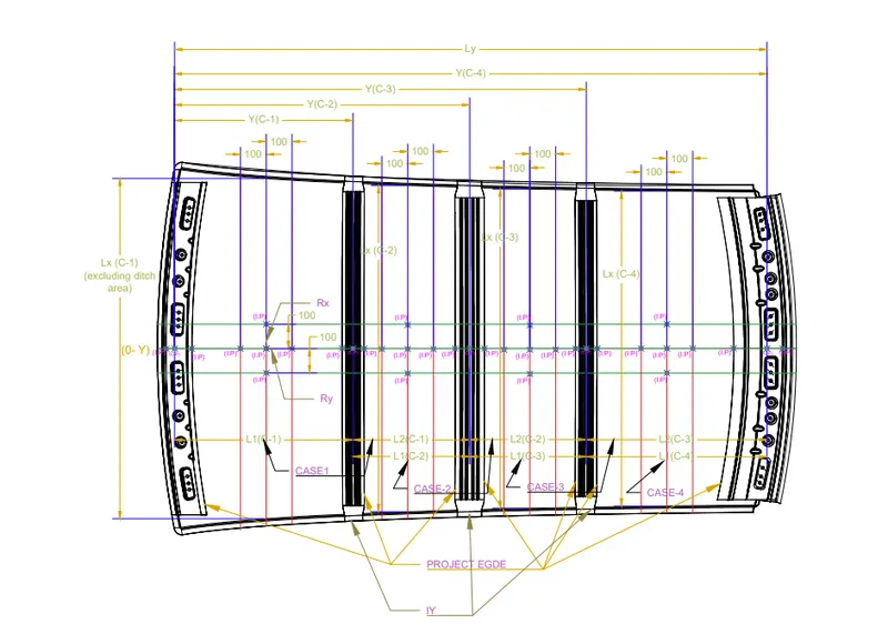
- Qr = [Iy x t2] / [α x s x [(Rx + Ry)/2]2 x 10-8]
- Note: The Qr value given over here is correct. There was a typo error in the formula given in the video.
- Where,
- α = My x Lx2 x 10-12 , My = Y(Ly-Y)
- t = Roof plate thickness [mm]
- Ly = Distance between the front and rear roof Rails on the Vehicle along with 0Y[mm]
- Length of Roof panel with the center point between Roof rail Front /Rear as the front and rear reference point.
- Lx = Distance between the Left and Right end of the roof on the Roof BOW [mm]
- The width of the roof panel is exposed on the surface.
- Y = Distance front Front Roof Rail to Roof BOW[mm]
- s = Distance for which Roof BOW bears divided load [mm]
- s = L1/2 + L2/2
- Iy = Geometrical moment of inertia of Roof BOW (Y cross-section )[mm4]
- Rx = Lateral direction curvature radius of roof panel Y cross-section on Roof BOW [mm]
- Roof panel curvature Radius of the Length Lx in Front view
- Ry = Longitudinal Direction curvature radius of the Roof panel X cross-section on Roof BOW [mm]
- Roof panel X curvature radius of length s in Side view
- Judgment condition
- Qr ≥ 3.1

Way to improve Qr if not satisfying :
- Increase the thickness of the roof.
- Accumulate more roof rails so that the space decrease between the rails.
- Increase the width of the rails.
- Create emboss.
Manufacturing Process for the Hood Assembly:
Drawing Operation:
- The deep drawing process is a forming process that occurs under a combination of tensile and compressive conditions. A flat sheet metal blank is formed into a hollow body open on one side or a hollow body is formed into a hollow body with a smaller cross-section.
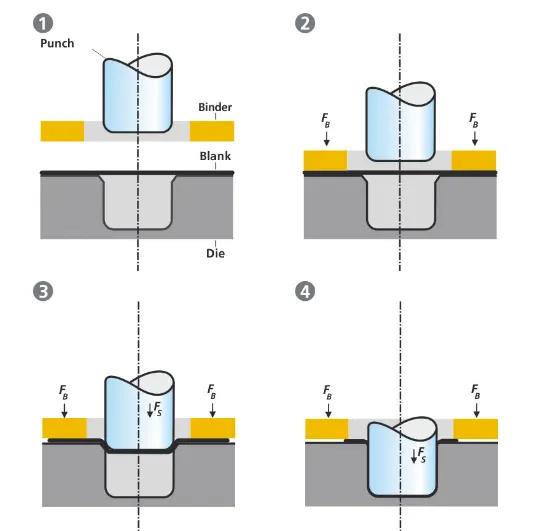
- The figure illustrates the deep drawing process. The rigid tools consist of a punch, die, and binder. In deep drawing, the plate holder closes after the metal sheet blank has been inserted.
- Next, the sheet is clamped between the die and the binder. This process slows down the flow of the sheet while it is being drawn and thereby prevents wrinkles from forming under the binder. The punch stretches the sheet over the die radius and forms it in the die. The amount of punch force necessary for forming is thereby continually increased up to the lower dead center of the punch.
- Whereas in pure deep drawing there is no reduction of sheet metal thickness, forming is achieved in stretch forming purely as a result of a decrease in sheet metal thickness. Stretch forming is extensively used for the forming of only slightly curved parts with low depth of draw (e.g. roofs, doors).
- When drawing complex car body parts in practice, there is usually a combination of stretch and deep drawing involved. It is necessary that the sheet metal is stretched as well as possible without reaching the material’s limits (e.g. splits, wrinkles).
- There are approximately 300 to 400 sheet metal parts that fit together to form the body of a car. In order to manufacture high-quality sheet metal parts optimally for their particular use, specialized software simulates the complete deep drawing process.
Spot welding:
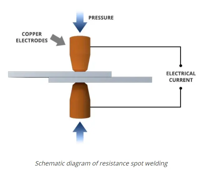
- Spot welding (also known as resistance spot welding) is a resistance welding process. This welding process is used primarily for welding two or more metal sheets together by applying pressure and heat from an electric current to the weld area.
- It works by contacting copper alloy electrodes to the sheet surfaces, whereby pressure and electric current are applied and heat is generated by the passage of current through resistive materials such as low-carbon steels.
Mastic Sealant:
- Mastic is preferred in place of spot weld only when the surface is an aesthetic surface.
-
Mastic is a form of sealant or adhesive used to fill the joints or as a bond for different materials and gaps. It is an elastic and flexible material used to create a durable bond between two different surfaces or to protect a particular surface.
- Cyanoacrylates are used extensively in the automotive industry, in large part because of their bond strength. They can also withstand extreme conditions, facilitating use in temperatures ranging from -40° to 250° F. Cyanoacrylates may be used in other cases where other glues or fasteners are not an option, as well.
- Application of adhesives and sealants enables automakers to simplify their assembly processes. Parts that are bonded together don't need holes to be drilled or punched, and assemblers don't need to measure torque or double-check fastening operations.
Test conducted on the roof after the assembly of the car:
Roll Over Test On Roof
- The rollover test is given by the Insurance Institute of highway safety ( IIHS). After analyzing many accidents IIHS has fixed some regulations about how to perform the test.
- IIHS rating is based on the following things which are how fast a car can reform its original shape after rollover and how deep a protrusion is.
- The aim of this test is to minimize the protrusion of the roof.
- Two conditions need to be followed while performing this test. One is to lock all the doors of the car properly and the second is to close all the windows of a car.
- Also, it is mandatory to fix the chassis on the hard lever surface horizontally.
- Load is applied at 25 degrees tilt when viewed from the front over the length of 762 mm.
- Load is applied at 5 degrees when viewed from the side, over the length of 1829 mm.
Conclusion:
- The Roof assembly has been successfully designed considering all the design Rules, Master sections, Manufacturing feasibility, Draft analysis, Heat distortion criteria, and Snow load analysis.