Roof Design
Aim: To create an ASSEMBLY by developing the essential flanges for the outer roof and creating the reinforcements for the Given Roof styling.
Theory:-
1: Roof:- An automobile roof or car top is the portion of an automobile that sits above the passenger compartment, protecting the vehicle occupants from sun, wind, rain, and other external elements.
2: Manufacturing Techniques:-
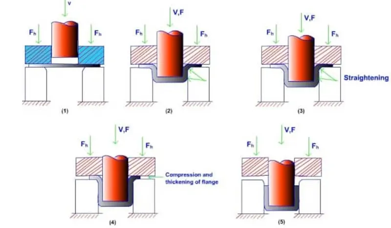
a. Deep Drawing:- In this, a Punch is used to form the required surface on the sheet metal simultaneously a taper angle is given in the workpiece for easy ejection of the punch after the process.
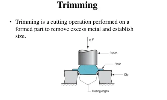
b. Trimming: - This operation is used to remove the excess material at the edge of the main sheet metal.
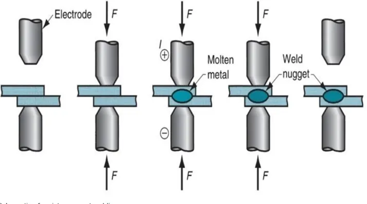
c. Spot Welding: - In this, two electrode is used and huge electric potential is created between the parts to pass current due to the resistance from the material fusion takes place and after the molten metal cools off small nuggets are created which are then removed via grinding.
d. Seam Welding: - This type of welding uses roller-type electrodes and the electric resistance of the parts to form continuous welds.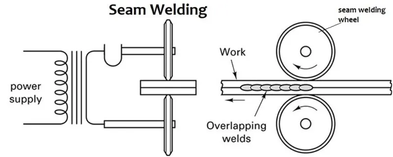
3: Roof Design: -
a. Design Considerations: -
> Good Head Room Clearance.
> Strong enough to withstand Rollover accidents.
> Good load-bearing capacity to withstand harsh weather conditions.
b. Components of the Roof:-
> Roof Outer
>Front Roof
> Front Bow Roof
> Centre Bow Roof
> Rear Bow Roof
> Rear Roof
c. Master Section:-
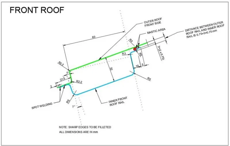
> Front Roof
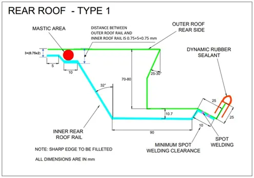
> Rear Roof:-
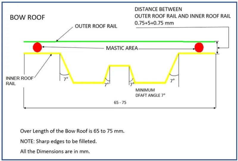
> Bow Roof (Front And Rear)
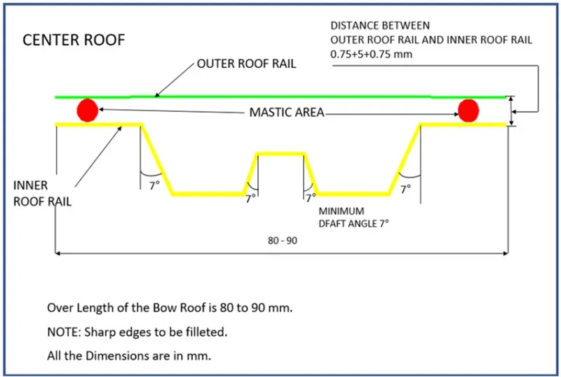
> Center Roof
3.1: Basic Design Steps in NX CAD:-
Note: As per the master section, thickness is provided of 0.75 mm.
> First we open an assembly in the NX CAD software and import the styling and then we name the component “Roof_Outer” following which we extract the outer face of the styling, using the extract command in the surface tab.
> Then we trim the excess part of the styling and put the remaining parts in a feature group called “Parent”.
> Now, following the master section we use the ‘law extension’ command from surface tab and make flanges for the front roof by providing a draft angle of 7 deg, so that during the manufacturing phase the tool can be removed easily after Pressing operation.
> Moving on, to the sides, we again use the law extension command to provide flanges on the sides of the roof and this time we provide a wider 10 deg draft angle as we have taken the Y axis as our prime draft angle.
> Also coming at the back, we then provide flanges for the Rear Roof.
> After completing the flanges we also provide embosses at the top of the roof.
> We then provide the face blends at appropriate places and using the Bridge curves and Studio Surface, we join the side flange with the front roof. Then we sew all the components.
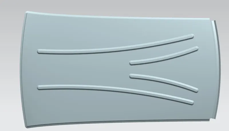
> Now in the assemble we make further parts using ‘Create New’ command in the assembly tab, and name them accordingly.
> After which we use the ‘WAVE GEOMETRY LINKER’ command from assembly tab to get the reference surface of the roof for making the lower part of the ‘Front roof’.
> We then offset the outer roof surface to 32.75 mm so as to provide a gap of 32 mm from the roof outer to the inner front roof, as per the master section.
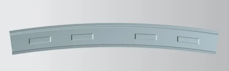
> Then we take the offset of the Roof_outer at 4.5 and 6.5mm in order to provide space of 5mm for the Mastics points taking into consideration for the components to be thickened both outwards and inwards and using the Trim and extend command we get our front roof reinforcement.
>Following this we provide embosses on the front roof so as to strengthen the reinforcement even more.
>Then we take the plane on the Roof outer at a certain distance ”Front Bow Roof”.
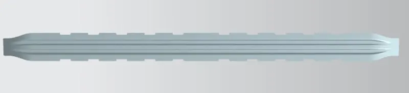
> Now, we move onto the ‘Front Bow roof’, we again use the ‘WAVE GEOMETRY LINKER’ command from the assembly tab to get the reference surface of the roof and then using the Offset command and following the master section, we provide the flanges and join them using the Trim and Extend Command.
> Then we provide the Face blends for the components to be smooth. After which we take a plane on the Bow roof and trim it from a certain distance in order to join it with the Outer roof Side flanges.
> Then we make and offset the side flanges of the outer roof and make it smaller according to our need using the Trim Command and then using the Through mesh curves and studio curves we join the Bow roof with the Side Flanges and check if there are any irregularities in the smoothness of the surface.
> Then we make cuts on the surface of the Bow Roof for the mastic points and using the Bridge curves we then smoothen all the sharp edges.

>With the above similar operation and following the Master section, we are able to replicate the results in the Centre and Rear bow roof as well.
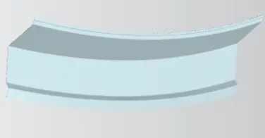
> Now we move on to make the “Rear Roof Reinforcement”, for which we use the ‘WAVE GEOMETRY LINKER’ command from the assembly tab to get the reference surface of the roof for making the lower part of the ‘Rear roof’.
> Then using the ‘Offset’ and ‘Trim And Extend Command‘, we are able to make the component.
3.2: Draft Analysis:-
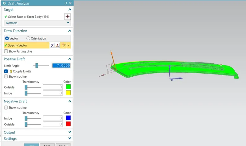
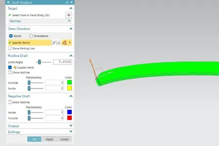
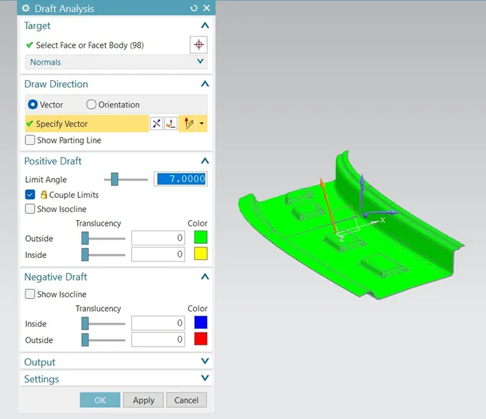
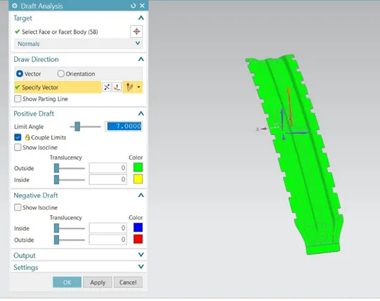
> As above stated that Roof Manufacturing uses the Press Forming Manufacturing techniques, hence Draft angle plays a significant role in the procedure, hence all the components are tested in NX CAD for the appropriate draft angle (Minimum 7 deg for Steel), hence by proving the Draft reference angle we are able to analyze the components that whether they are able to be manufactured or not. And below are the Results:-
1. Roof_Outer
a.With Embosses
b. Without Embosses
2. Front Roof Reinforcement
3. Front Bow Roof:-
4.Center Bow Roof
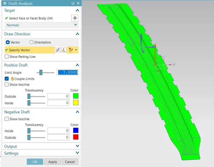
5. Rear Bow Roof
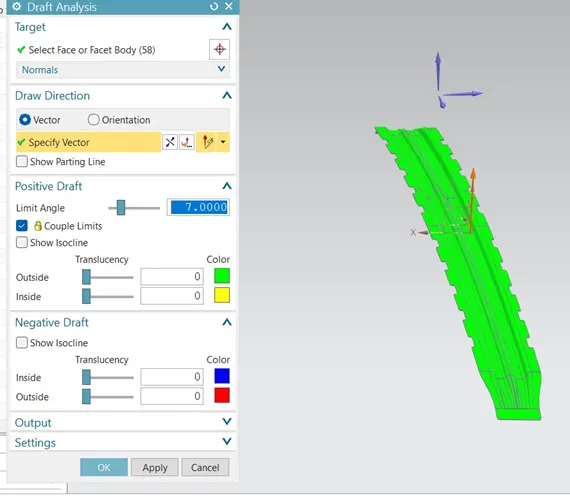
6. Rear Roof Reinforcement
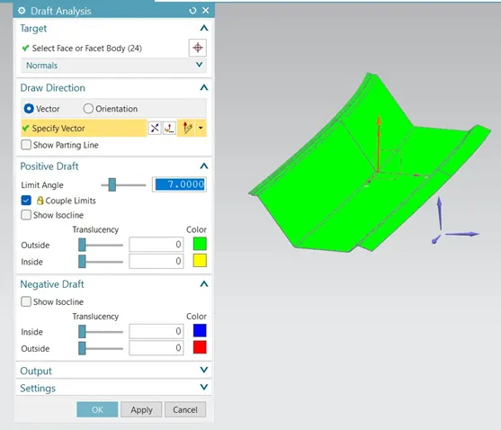
3.3: Calculations:-
> Now after the Draft analysis, we analyze the Roof on two very important criteria, which are ‘HEAT DISTORTION CRITERIA’ and ‘SNOW LOAD CRITERIA’, as the Roof is the Exterior component that is subjected to Extreme Temperature as well as Harsh Weather conditions, the above two criteria’s are very essential.
> At first take a plane parallel to our roof Outer and sketch the points on which we will do our curvature study and find out whether they are at an optimum level or there are improvements needed.
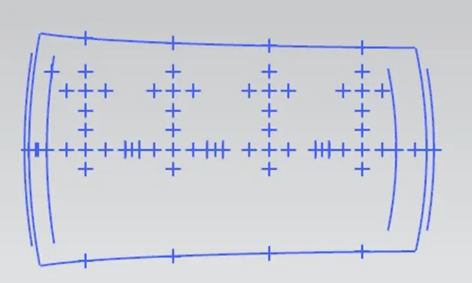
> Now we project this sketch on the Roof and using the ‘Arc/Circle’ command from the Curve Tab and ‘Simple Radius’ command from the Analysis tab we Find out the required values to calculate the HEAT DISTORTION CRITERIA’ and ‘SNOW LOAD CRITERIA’.
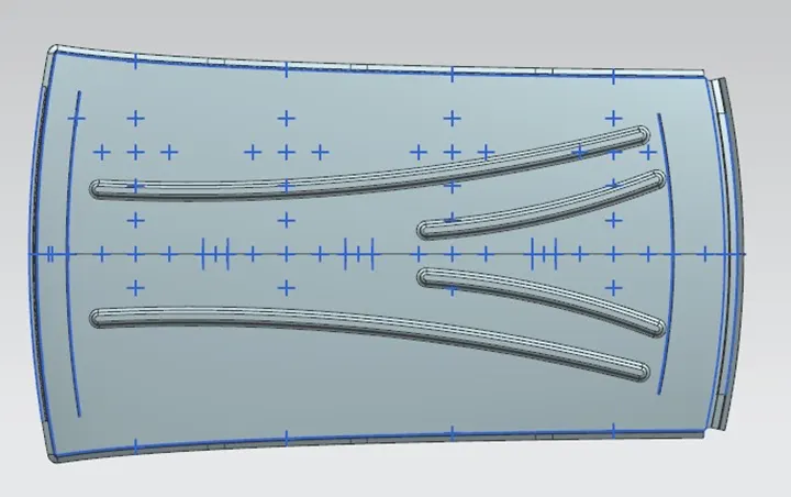
> For the above two criteria we follow the below two formulas:-
1. Heat Distortion Criteria:-
W = [1.73 x 10^(-3) x L] + [1.85 x 10^(-8) x (R^2)/t] + [ 1.10x10^(-3) x l] - 2.68
Where,
L = Roof Length in X-Direction[mm](Roof dimension in 0-Y)
R = Roof curvature
R = 2(Rx*Ry)/(Rx+Ry)
Rx = X curvature
Ry = Y curvature
t = Roof plate thickness [mm]
l = Bow Roof Span [mm]
Judgment Condition: OK< 2.7
- Snow Load Criteria:-
Qr = [Iy x t2] / [α x s x [(Rx + Ry)/2]2 x 10-8]
Note: The Qr value given over here is correct. There was a typo error in the formula given in the video.
Where,
α = My x Lx2 x 10-12 , My = Y(Ly-Y)
t = Roof plate thickness [mm]
Ly = Distance between the front and rear roof Rails on the Vehicle along with 0Y[mm]
Length of Roof panel with the center point between Roof rail Front /Rear as the front and rear reference point.
Lx = Distance between the Left and Right end of the roof on the Roof BOW [mm]
The width of the roof panel is exposed on the surface.
Y = Distance front Front Roof Rail to Roof BOW[mm]
s = Distance for which Roof BOW bears divided load [mm]
s = L1/2 + L2/2
Iy = Geometrical moment of inertia of Roof BOW (Y cross-section )[mm4]
Rx = Lateral direction curvature radius of roof panel Y cross-section on Roof BOW [mm]
Roof panel curvature Radius of the Length Lx in Front view
Ry = Longitudinal Direction curvature radius of the Roof panel X cross-section on Roof BOW [mm]
Roof panel X curvature radius of length s in Side view
Judgment condition
Qr ≥ 3.1
250 ≤ s ≤ 380
> We have created an Excel Sheet for the above calculation and below are the Results:-
1. Heat Distortion Criteria: -
(At 3Y line)

2. Snow Load Criteria: -
(At 0Y line)

4.1: Curvature Study:-
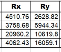
> We have also checked whether introducing new embosses over the roof_outer does impact the above calculations as the radius of curvature gets altered by introducing the embosses and below are the results:-
1. Heat Distortion Criteria:-
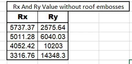
Rx and Ry values with embosses: -
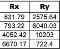
2. Snow Load Criteria:- 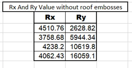
Rx and Ry Values with Roof Embosses: -
5: Results and Conclusions: -
> As we can see in the above calculation section, our roof is meeting all the criteria for the Heat distortion prediction, but fails in the Snow load condition, hence we suggest the below possible remedies be applied: -
a. Cross Checking the placement of the Bow Roofs as the criteria ‘s’ and ‘Qr’ are dependent on it.
b. Checking the offset values of the Bow Roof Flanges as it impacts the MOI of the component, thus impacting the ‘Qr’.
c. We can provide certain values of radius of curvature and other components from our end to the design styling team which meet the criteria, but that will be dependent on that team to apply those values of curvature or not.