Roof Design
AIM
1) Development of flanges for the outer roof and creating the reinforcements.
2) Performing draft analysis on the reinforcements
3) Performing curvature study on the roof. The studies include the following
(i) Bow–Roof Prediction Formula
(ii) Snow Load Prediction Formula
1) Development of flanges for the outer roof and creating the reinforcements.
(i) Development of flanges on front side
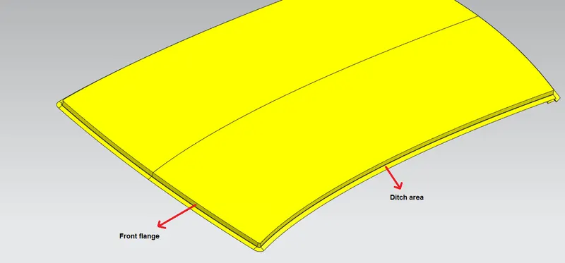
The front side flanges are developed as per the given master section with draft angle 7 degrees and thickness of 0.75mm using law extension, blend, mirror, sew & thicken commands.
(ii) Development of flanges on rear side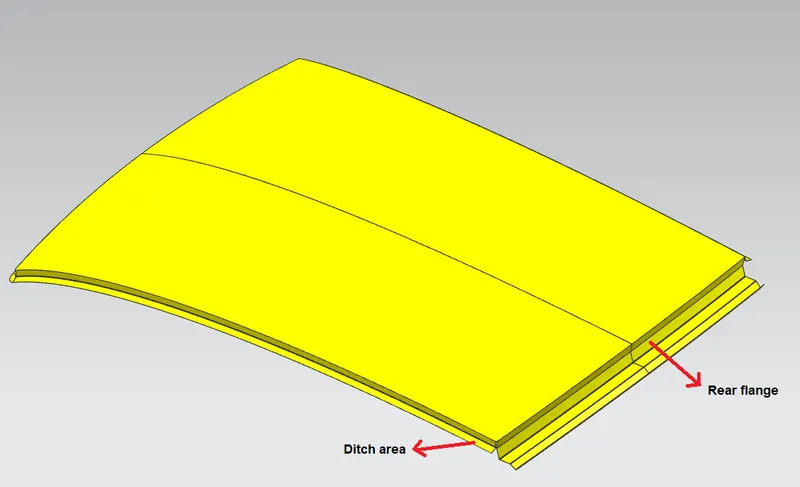
The front side flanges are developed as per the given master section using law extension, blend, mirror, sew & thicken commands.
(iii) Development of Reinforcements
(a) Front roof rail
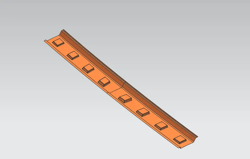
The front roof rail developed as per the given master section with draft angle of 7 degrees and thickness of 0.75mm using law extension, blend, mirror, sew & thicken commands.
(b) Rear roof rail
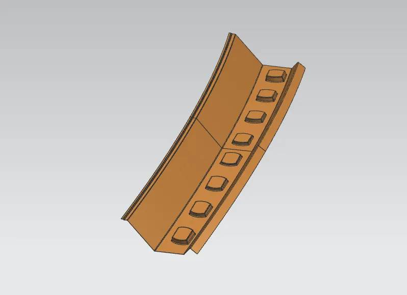
The rear roof rail is developed as per the given master section using law extension, blend, mirror, sew & thicken commands.
(c) Bow roof 1
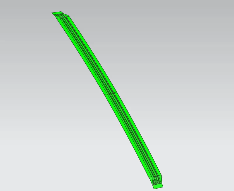
To develop bow roof 1, a plane is created and positioned at 25% of the outer roof curve arc length from the front side and then intersected with roof to form a curve. With reference to this intersection curve, bow roof is developed using the given Master section.
(iii) Centre roof
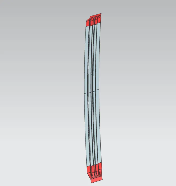
To develop centre roof, a plane is created and positioned at 50% of the outer roof curve arc length from the front side and then intersected with roof to form a curve. With reference to this intersection curve, bow roof is developed using the given Master section.
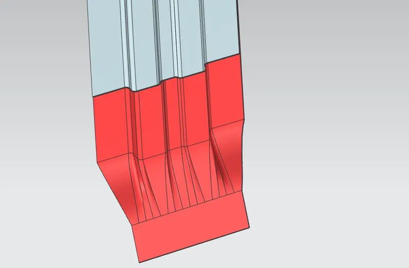
Centre roof comprises of two reinforcements one on top of the other to provide more strength at the centre region of the roof.
(iv) Bow roof 2
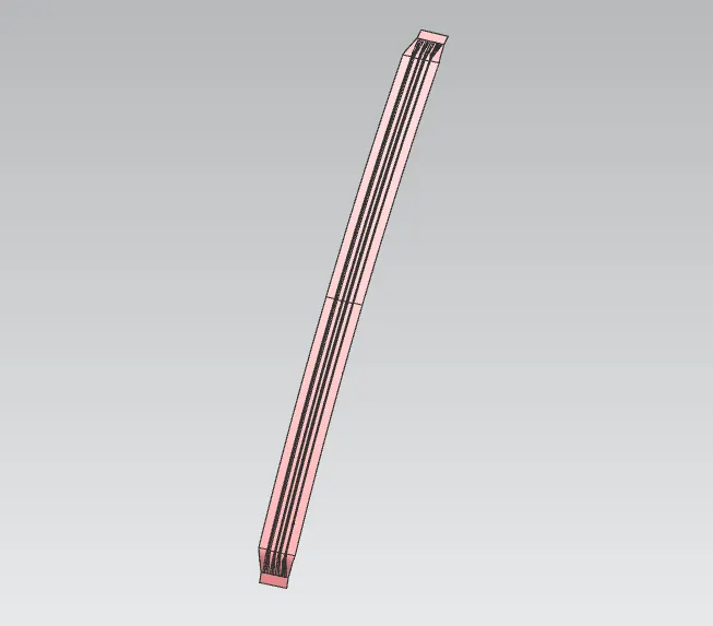
To develop bow roof 1, a plane is created and positioned at 75% of the outer roof curve arc length from the front side and then intersected with roof to form a curve. With reference to this intersection curve, bow roof is developed using the given Master section.
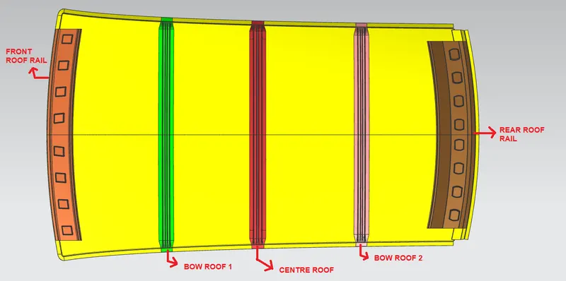
The above figure shows the outer roof with reinforcements Front roof rail, bow roof 1, centre roof, bow roof 2 and rear roof rail.
2) Performing draft analysis on the reinforcements
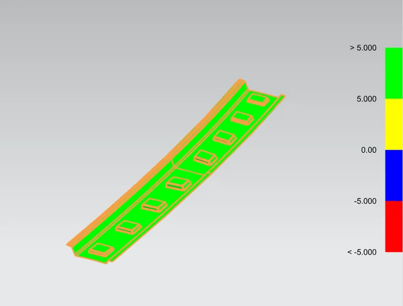
(i) Draft analysis on Front roof rail
(ii) Draft analysis on Bow roof 1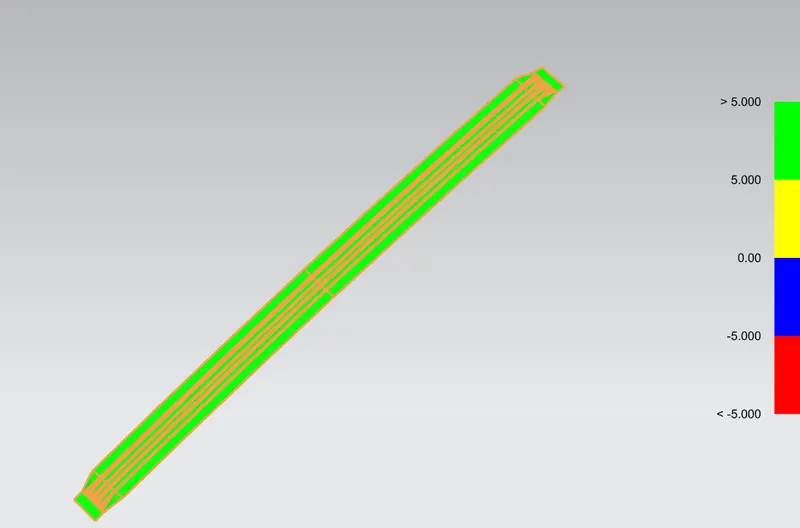
(iii) Draft analysis on Centre roof
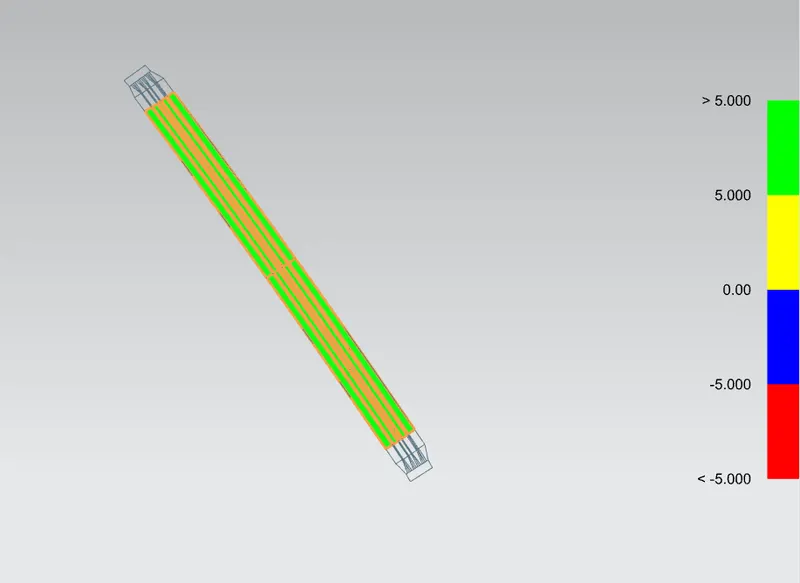
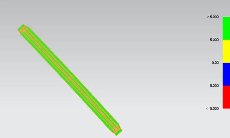
(iv) Draft analysis on Bow roof 2
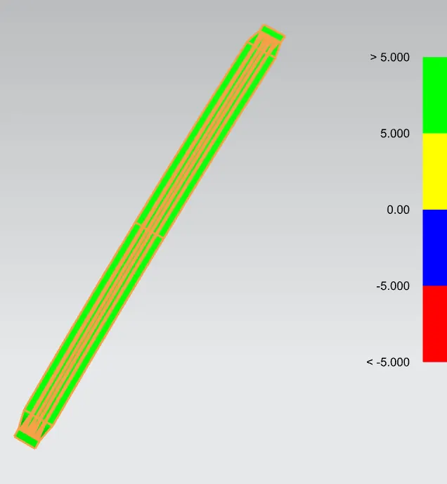
(v) Draft analysis on Rear roof rail
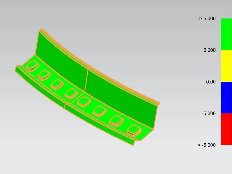
From the above images, it is evident that the all the reinforcements dimensions satisfy the & degree draft angle criterion for the tooling direction along the y axis.
3) Performing curvature study on the roof
Curvature study of the roof provides us the information about whether the positioning of the bow roofs or reinforcements are exact or not, if not , the remedies would be changing their positions or to add more or create embosses for strengthening of the roof. The following studies are to performed for curvature study.
(i) Bow–Roof Prediction Formula
W = [1.73 x 10^(-3) x L] + [1.85 x 10^(-8) x (R^2)/t] + [ 1.10x10^(-3) x l] - 2.68
Where,
L = Roof Length in X-Direction[mm](Roof dimension in 0-Y)
R = Roof curvature
R = 2(Rx*Ry)/(Rx+Ry)
Rx = X curvature
Ry = Y curvature
t = Roof plate thickness [mm]
l = Bow Roof Span [mm]
Judgment Condition
OK< 2.7
Ly or L measurement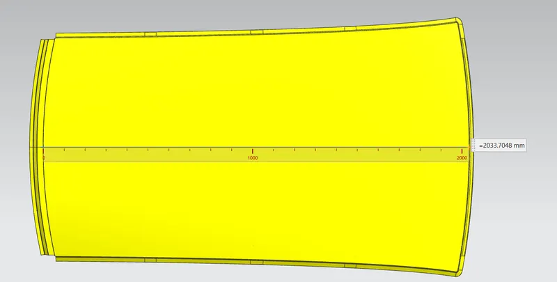
Rx and Ry measurement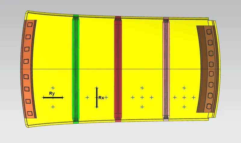
Bow roof span meaurement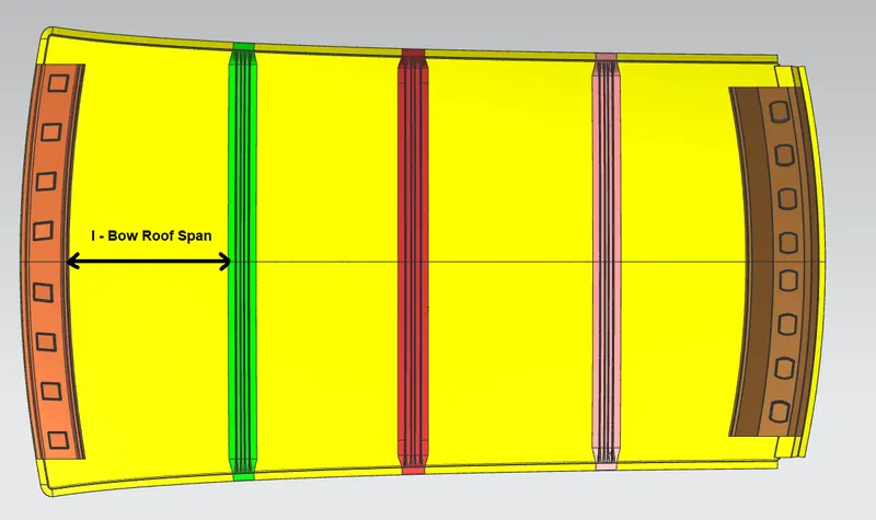
t - thickness = 0.75mm
BOW ROOF PREDICTION
| S no | Roof rails | Rx (mm) | Ry(mm) | Rx*Ry(mm) | Rx+Ry(mm) | 2*Rx*Ry(mm) | R = (2*Rx*Ry)/Rx+Ry | Ly(mm) | t(mm) | I(mm) | 1.73*10^-3*L | R^2/t | 1.85*10^-8*R^2/t | 1.10*10^-3*I | W | Result |
| 1 | FR - Bowroof1 | 5720.5442 | 5720.5442 | 32724625.94 | 11441.0884 | 65449251.89 | 5720.5442 | 2034.3785 | 0.75 | 423.5805 | 3.519474805 | 43632834.59 | 0.80720744 | 0.46593855 | 2.112621 | OK |
| 2 | Bowroof1-Centreroof | 4921.4956 | 6437.8309 | 31683756.45 | 11359.3265 | 63367512.9 | 5578.456865 | 2034.3785 | 0.75 | 373.5242 | 3.519474805 | 41492241.33 | 0.767606465 | 0.41087662 | 2.017958 | OK |
| 3 | Centreroof-Bowroof2 | 3982.4503 | 10555.8065 | 42037974.76 | 14538.2568 | 84075949.53 | 5783.08326 | 2034.3785 | 0.75 | 433.677 | 3.519474805 | 44592069.32 | 0.824953282 | 0.4770447 | 2.141473 | OK |
| 4 | Bowroof2-Rearroof | 3305.3884 | 14422.7373 | 47672748.57 | 17728.1257 | 95345497.14 | 5378.205161 | 2034.3785 | 0.75 | 329.757 | 3.519474805 | 38566787.67 | 0.713485572 | 0.3627327 | 1.915693 | OK |
The bow roof prediciton criterion for all regions satisfy the judgement condition i.e., W<2.7
(ii) Snow Load Prediction Formula
Qr = [Iy x t2] / [α x s x [(Rx + Ry)/2]2 x 10-8]
Where,
α = My x Lx2 x 10-12 , My = Y(Ly-Y)
t = Roof plate thickness [mm]
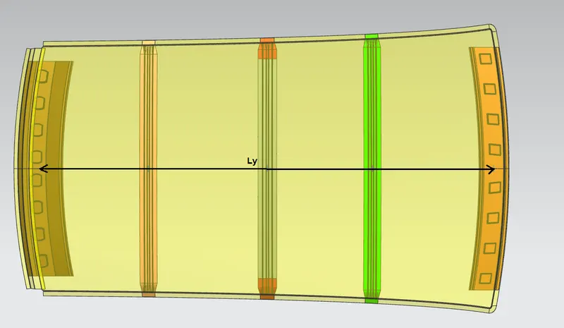
Ly = Distance between the front and rear roof Rails on the Vehicle along with 0Y[mm]
Length of Roof panel with the center point between Roof rail Front /Rear as the front and rear reference point.
Lx = Distance between the Left and Right end of the roof on the Roof BOW [mm]
The width of the roof panel is exposed on the surface.
Y = Distance front Front Roof Rail to Roof BOW[mm]
s = Distance for which Roof BOW bears divided load [mm]
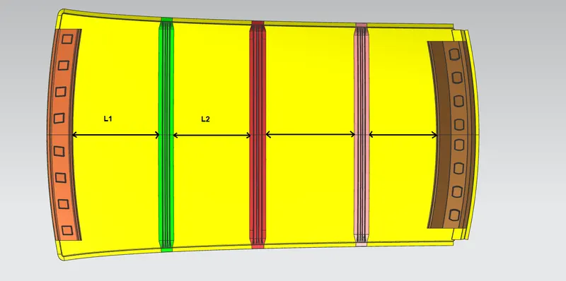
s = L1/2 + L2/2
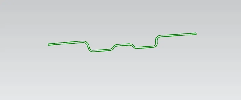
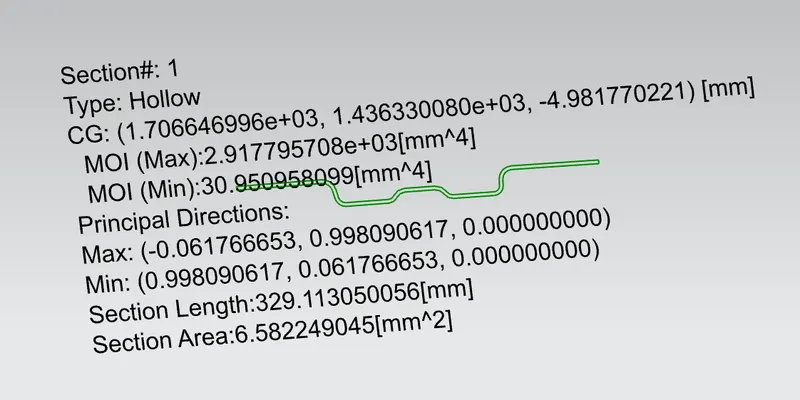
Iy = Geometrical moment of inertia of Roof BOW (Y cross-section )[mm4]
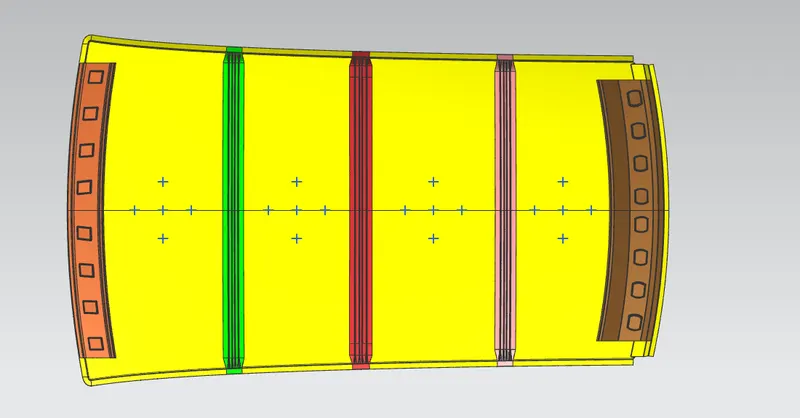
Rx = Lateral direction curvature radius of roof panel Y cross-section on Roof BOW [mm]
Roof panel curvature Radius of the Length Lx in Front view
Ry = Longitudinal Direction curvature radius of the Roof panel X cross-section on Roof BOW [mm]
Roof panel X curvature radius of length s in Side view
Judgment condition
Qr ≥ 3.1
Ly measurement
Lx meaurement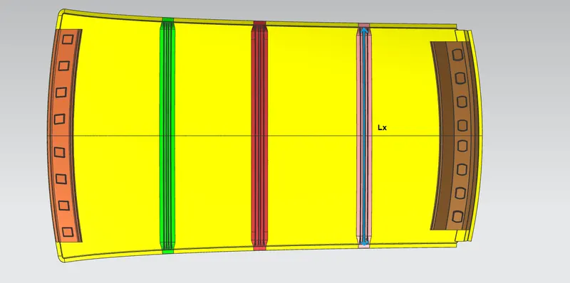
L1 & L2 meaurement
Rx & Ry measurement
Iy measurement
(a) Bowroof 1
(b) Centreroof
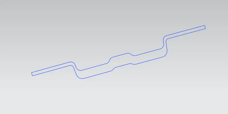
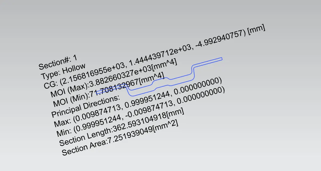
(c) Bowroof 2
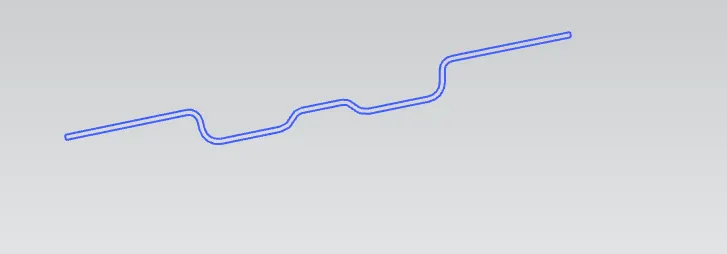
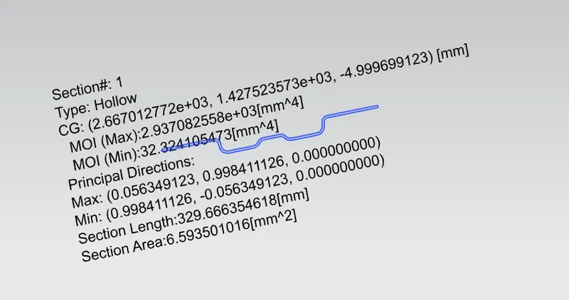
SNOW LOAD PREDICTION
| S no | Roof rails | Rx | Ry | Rx+Ry | Iy | Y | Ly | Ly-Y | Y(Ly-Y)=[My] | Lx | Lx2 | My*Lx2*10^-12 | L1 | L2 | L1/2 | L2/2 | S | t | Iy*t^2 | (Rx+Ry)/2 | ((Rx+Ry)/2)^2 | Qr | Result |
| 1 | FR - Bowroof1 | 4414.393 | 2775.955 | 7190.348 | 2917.8 | 526.6214 | 1941.344 | 1414.722 | 745022.986 | 1106.726 | 1224843 | 0.91253643 | 526.6214 | 450.3844 | 263.3107 | 225.1922 | 488.5029 | 0.75 | 1641.263 | 3595.174 | 12925274.65 | 28.48531 | OK |
| 2 | Bowroof1-Centreroof | 3777.242 | 6353.664 | 10130.91 | 3882.66 | 977.0058 | 1941.344 | 964.3378 | 942163.624 | 1075.987 | 1157748 | 1.090788074 | 450.3844 | 510.5888 | 225.1922 | 255.2944 | 480.4866 | 0.75 | 2183.996 | 5065.453 | 25658811.06 | 16.24029 | OK |
| 3 | Centreroof-Bowroof2 | 4273.635 | 9391.504 | 13665.14 | 2937 | 1487.595 | 1941.344 | 453.749 | 674994.562 | 1054.535 | 1112044 | 0.750623982 | 510.5888 | 466.9179 | 255.2944 | 233.459 | 488.7534 | 0.75 | 1652.063 | 6832.569 | 46683999.82 | 9.645977 | OK |
The snow load prediciton criterion for all regions satisfy the judgement condition i.e., Qr>=3.1
Conclusion
Strength criterion for car roof
If the roof has good curvature through the entire surface, it requires less reinforcements. If the surface is close to flat or flat, reinforcements are required to improve the overall strength of the roof. These reinforcements are positioned at those flat surfaces or regions for better strength.
Results
The development of reinforcements bowroof 1 , centre roof and bow roof 2 at the current positions satisfy the bow roof prediction criterian ., i.e W < 2.7 and the snow load criterian i.e., Qr>=3.1. These results draw an inference that the current positions of bow roofs are good and doesnt need any repositioning, and also the strength of the roof has been improved by the reinforcements and may not reuire additional reinforcements.