Roof Design
ROOF DESIGN
OBJECTIVE :
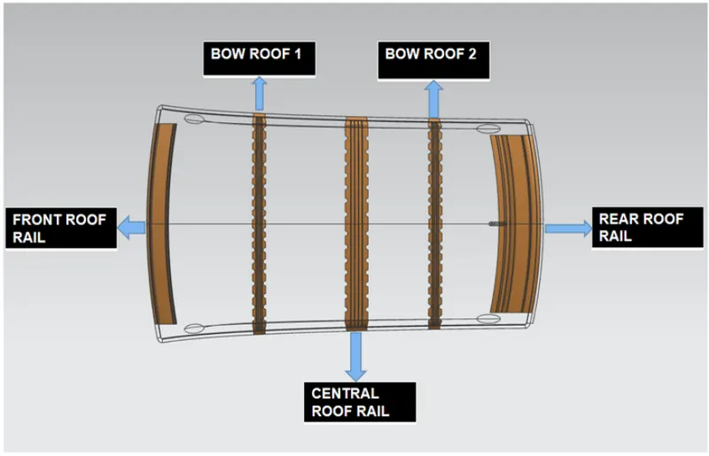
- The objective of this project is to design car roof with essential flanges and reinforcements like ditch area , front roof rail , bow roofs, central roof rail and rear roof rail for the the given styling surface
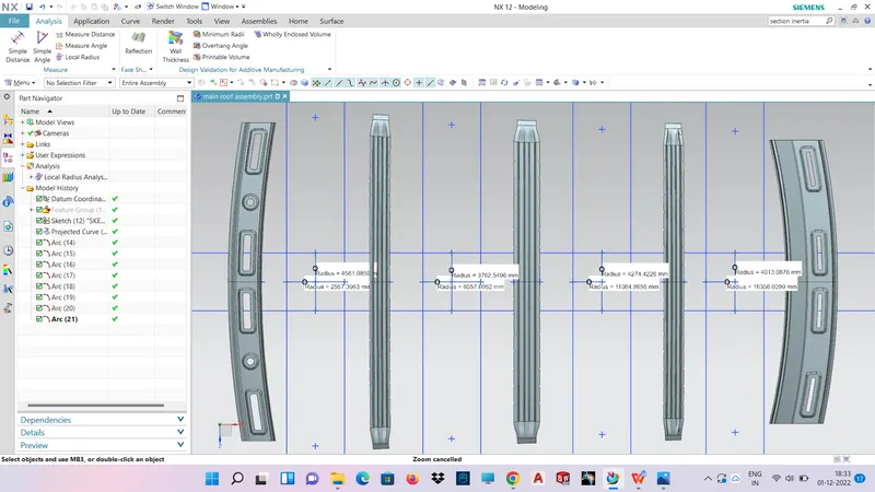
- Perform a curvature study on the roof and perform the calculations for the heat distortion and snow load criteria to determine whether the bow roofs are at the correct positions.
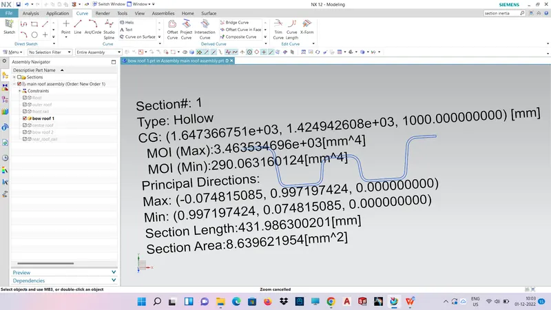
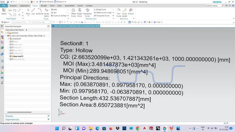
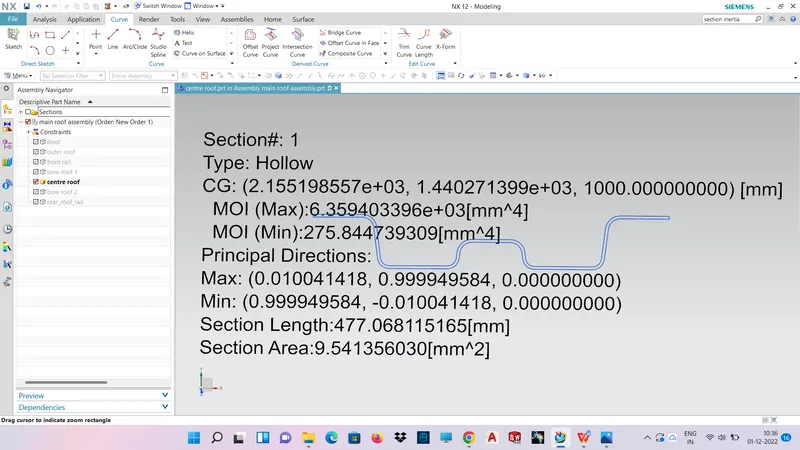
- Finding moment of inertia and section modulus for Bow roofs , central roof rail . front roof rail and rear roof rail .
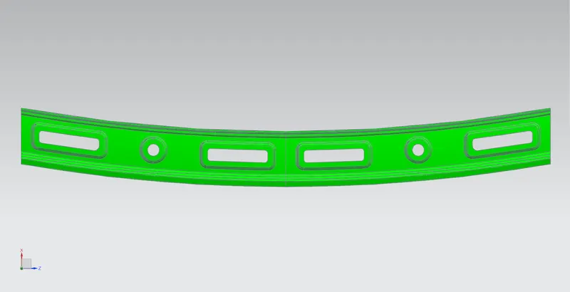
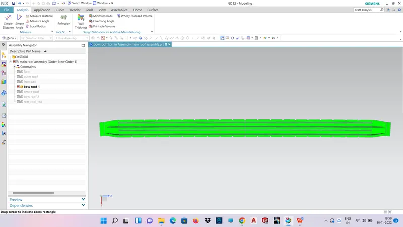
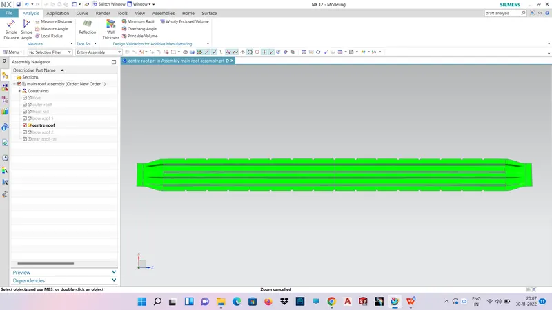
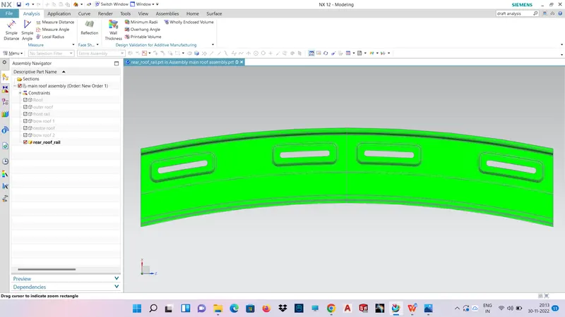
- Perform the draft analysis for each reinforcements
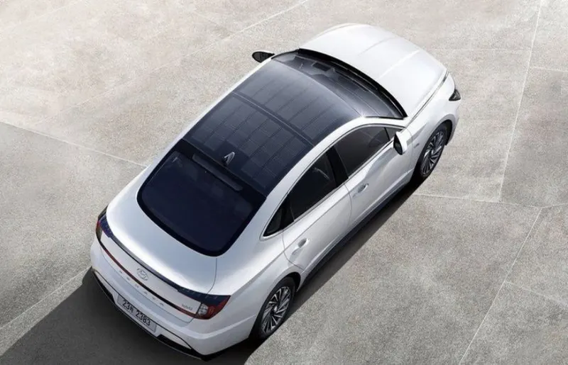
CAR ROOF :
An automobile roof or car top is the portion of an automobile that sits above the passenger compartment, protecting the vehicle occupants from sun, wind, rain, and other external elements. Roof is the structure above the wind shield glass having the reinforcements to provide the strength to the overall structure and to with stand the over head forces like snow.
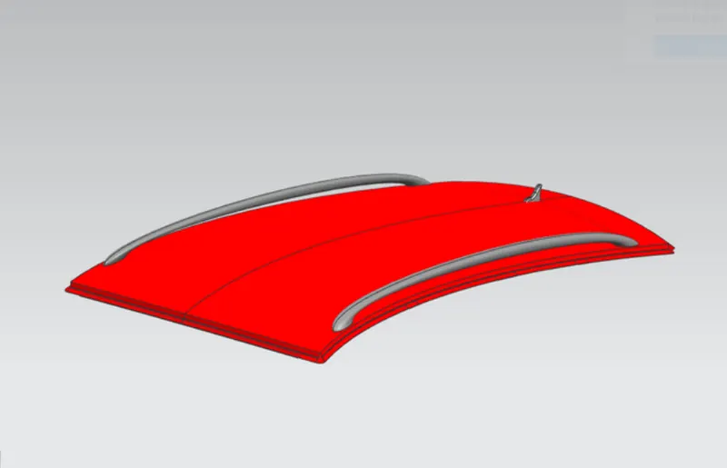
WHY REINFORCEMENTS :
If the roof is flat it is very weak and cannot able to with stand the forces like snow , so in order to increase the strength of the roof these reinforcements like front roof rail, central roof rail, rear roof rail and the bow roofs are introduced and joined to the flat surface of the roof with the different joining process
DESIGN CONSIDERATION OF ROOF:
- Visibility criteria
- Head room clearance
- Bow roof position
- Heat distortion and Snow load criteria
- Draft analysis
COMPONENTS INCLUDED IN ROOF
- Roof front rail
- Bow roof
- Centre roof
- Roof reinforcement
- Roof rear rail
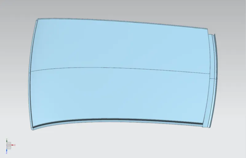
ROOF OUTER PANEL
It is the largest and outermost surface of th car or an automobile.
It is rested on rail,bows,reinforcement
ROOF FRONT RAIL
Front roof rail is used for supporting the roof for externally applied forces occurring at accidents. When we increasing the front roof rail is good for strength but also it is not for drivers because of it hide visibility of road.
When considering the parameters of roof rail, give them 60-80mm length, proper draft angle and also using the embosses for increasing the strength. Front section of front roof rails spot welded to the front ditch area and other end is fixed with help of mastic sealants.
Sheet metal thickness t = 0.75mm
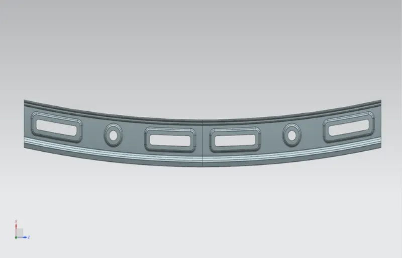
DRAFT ANALYSIS OF FRONT ROOF RAIL
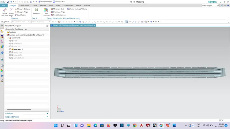
BOW ROOF 1
Create an intersection curve with the help of the plane and select the bow roof 1
DRAFT ANALYSIS OF BOW ROOF 1
CENTER ROOF
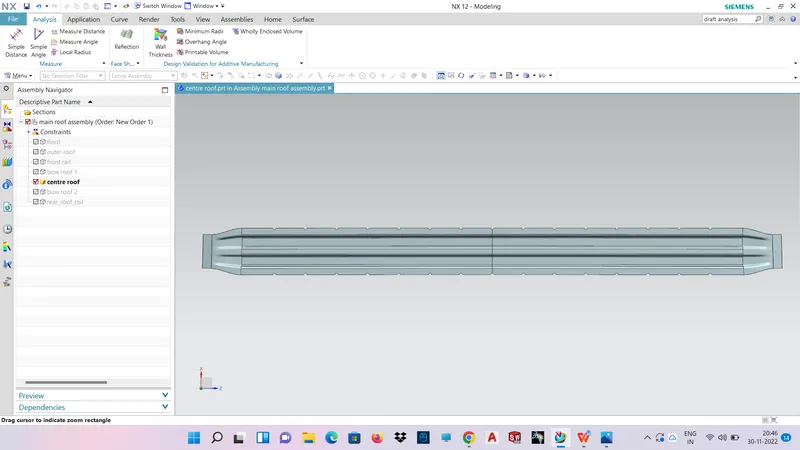
DRAFT ANALYSIS OF CENTER ROOF
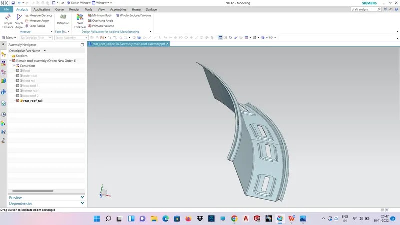
REAR ROOF RAIL
DRAFT ANALYSIS OF REAR ROOF RAIL
Bow–Roof Prediction Formula
W = [1.73 x 10^(-3) x L] + [1.85 x 10^(-8) x (R^2)/t] + [ 1.10x10^(-3) x l] - 2.68
Where,
L = Roof Length in X-Direction[mm](Roof dimension in 0-Y)
R = Roof curvature
R = 2(Rx*Ry)/(Rx+Ry)
Rx = X curvature
Ry = Y curvature
t = Roof plate thickness [mm]
l = Bow Roof Span [mm]
Judgment Condition
OK< 2.7
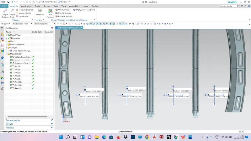
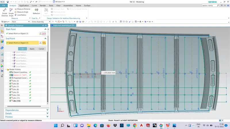
HEAT DISTORTION
|
S.NO |
SECTION |
Rx(mm) |
Ry(mm) |
R(mm) |
L(mm) |
t(mm) |
I(mm) |
R^2/t |
W |
OK/NG |
|
1 |
FR-BR1 |
5740.34 |
2496.26 |
3479.44 |
2024.87 |
0.75 |
373.35 |
16145065.67 |
1.532 |
OK |
|
2 |
BR1-CR |
4983.96 |
6150.33 |
5506.36 |
2024.87 |
0.75 |
428.58 |
40426667.27 |
2.042 |
OK |
|
3 |
CR-BR2 |
3980.05 |
10567.90 |
5782.36 |
2024.87 |
0.75 |
428.53 |
44580916.23 |
2.119 |
OK |
|
4 |
BR2-RR |
3284.38 |
14560.37 |
5359.76 |
2024.87 |
0.75 |
351.63 |
38302703.01 |
1.918 |
OK |
Snow Load Prediction Formula
Qr = [Iy x t2] / [α x s x [(Rx + Ry)/2]2 x 10-8]
Note: The Qr value given over here is correct. There was a typo error in the formula given in the video.
Where,
α = My x Lx2 x 10-12 , My = Y(Ly-Y)
t = Roof plate thickness [mm]
Ly = Distance between the front and rear roof Rails on the Vehicle along with 0Y[mm]
Length of Roof panel with the center point between Roof rail Front /Rear as the front and rear reference point.
Lx = Distance between the Left and Right end of the roof on the Roof BOW [mm]
The width of the roof panel is exposed on the surface.
Y = Distance front Front Roof Rail to Roof BOW[mm]
s = Distance for which Roof BOW bears divided load [mm]
s = L1/2 + L2/2
Iy = Geometrical moment of inertia of Roof BOW (Y cross-section )[mm4]
Rx = Lateral direction curvature radius of roof panel Y cross-section on Roof BOW [mm]
Roof panel curvature Radius of the Length Lx in Front view
Ry = Longitudinal Direction curvature radius of the Roof panel X cross-section on Roof BOW [mm]
Roof panel X curvature radius of length s in Side view
Judgment condition
Qr ≥ 3.1
250 ≤ s ≤ 380
SECTION INERTIA ANALYSIS
FOR BOW ROOF 1
FOR BOW ROOF 2
FOR CENTRE RAIL
SNOWED CONDITION
|
S.NO |
SECTION |
Iy(mm4) |
Lx(mm) |
Ly(mm) |
Y(mm) |
L1(mm) |
L2(mm) |
Rx(mm) |
Ry(mm) |
t(mm) |
alpha |
s(mm) |
My |
Qr |
REMARK |
|
1 |
FR-BR1 |
290.06 |
1110.53 |
1975.05 |
452.68 |
452.68 |
508.50 |
4561.05 |
2557.39 |
0.75 |
0.84 |
480.59 |
689146.45 |
6.19 |
OK |
|
2 |
BR1-CR |
275.84 |
1070.39 |
1975.05 |
961.19 |
508.50 |
508.47 |
3762.54 |
6057.60 |
0.75 |
1.11 |
508.48 |
974512.09 |
4.14 |
OK |
|
3 |
CR-BR2 |
289.94 |
1048.84 |
1975.05 |
1469.66 |
508.47 |
505.38 |
4274.42 |
11064.96 |
0.75 |
0.81 |
506.92 |
742721.14 |
2.9 |
NG |
Conclusion:
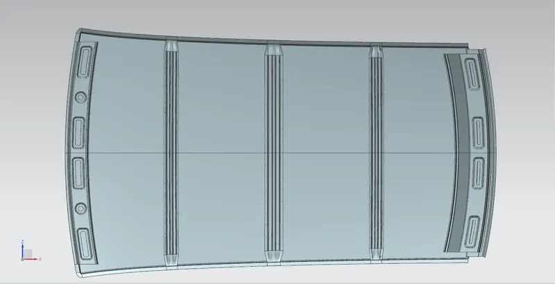
- Designed Roof reinforcements such as Front roof rail, Bow roofs, Centre Roof rail, Rear Roof Rail and Ditch area as per given master sections
- Performed Draft analysis for all reinforcements
- Performed Section Inertia Analysis
- Peformed Curvature study and calculated Heat Distortion Criteria & Snow Load criteria
By performing above actions, I learnt and designed Roof reinforcements