Roof Design
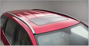
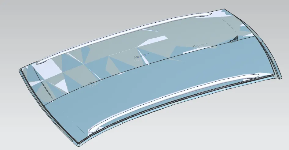
The component of an automobile that is located above the passenger compartment and shields the occupants from the sun, wind, rain, and other environmental factors is called the car top or roof.
INTRODUCTION :
every products design begins with requirements.the design engineer designs the sketch of the product.with the use of sophisticated CAD software @D sketch with the correct dimension is then channgred into an #D model.another crucial aspect of designing is that a product which is designed must be able to manufactured.therfore a designers job is to design less expensive product and produce a simple design as possible.thos is where assembly design & and manufacturing design are located.
Main Parts Of Roof :-
1.the roof has an outer part which is the styling part.
2.strengthing parts are avilable below the outer panel of the roof,which are bow roof ,centre roof rail & rear roof rail.
3.the front roof provides the provison for the windshield glasses.
4.the rear roof rail has hinge mounting for the back door.it is attached to aportion where the the backdoor meets the roof.
5.Bow roof rails are present in between the front roof rail and centre roof rail,centre roof rail and rear roof rail to provide support to the panel.
6.reinforcement centre is used as a cross cemtre between left and right hand bodies.
Design Of Roof Rail and Bow Roofs :-
front roof rail
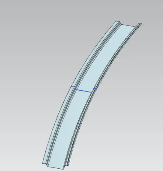
Bow Roof 1 :-
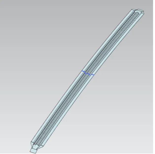
Centre Reinforcement :-
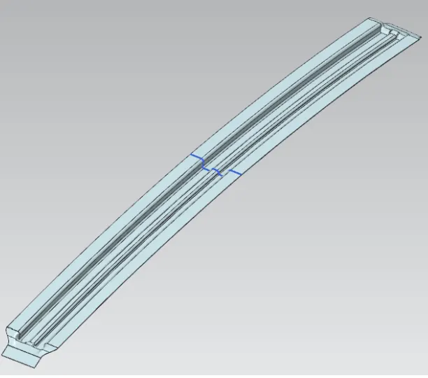
Bow Roof 2 :-
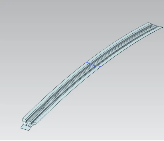
Roof Outer Panel :-
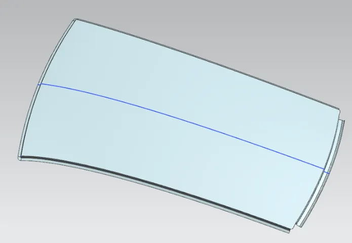
SECTION MODULUS :
when designing beams ,section modulus for a specific cross section is taken into consideration.other geomentric properties taken into accont are tension and shear ,radius pf grant ion for commpression,moment of inertia and polar moment of inertiafor stiffness.equatoions for section modulus is found below.
There are two types of section moduli :
The elastic section modulus and The plastic section modulus.
The elastic section modulus is defined as,
s= 1/ y
where :
S= Section modulus
I = second moment of inertia (or area moment of inertia,not to be conf used with moment of inertia)
y = the distance from the neutral axis to any given fibre.It is often reported using y = c,where c is the distance f rom the neutral axis to the most extreme fibre.
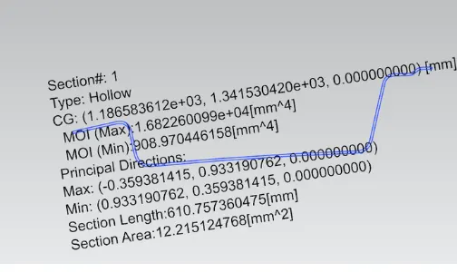
A.Front Roof Rail :-
- The minimum Moment Of inertia of the Bow Roof Section is 908.9 mm4
-
I=908.9 mm^4
y=123 mm
S=I/y=7.389 mm^3
-
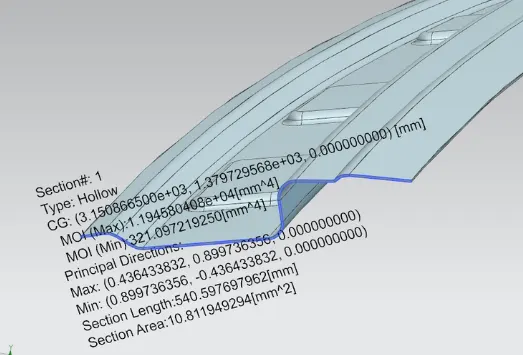
B. Rear Roof Rail :-
- The minimum Moment Of inertia of the Bow Roof Section is 321.0 mm4
-
I=321.0 mm^4
y=117 mm
S=I/y=2.74 mm^3
-
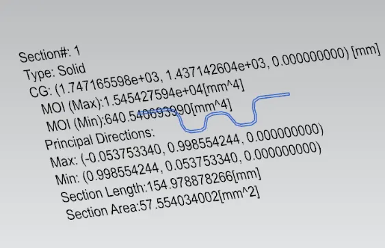
Bow Roof Rail 1 :-
- The minimum Moment Of inertia of the Bow Roof Section is 640.0 mm4
- I=640.0 mm^4
y=59mm
S=I/y=10.84mm^3
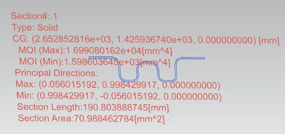
Bow Roof Rail 2 :-
- The minimum Moment Of inertia of the Bow Roof Section is 1.59 mm4
- I=1.59 mm^4
y=59mm
S=I/y=0.02mm^3
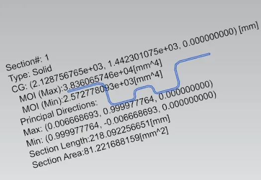
Center Roof Rail :-
- The minimum Moment Of inertia of the Bow Roof Section is 2.57 mm4
- I=2.57 mm^4
y=79mm
S=I/y=0.03mm^3
Heat Distortion Analysis :-
Heat distortion analysis plays a pivotal role in the strength of the roof panel. It is the temperature above which material cannot be used for structural applications.
This study is used to predict the heat distortion temperature where the material starts to soften when exposed to a fixed load at elevated temperature.
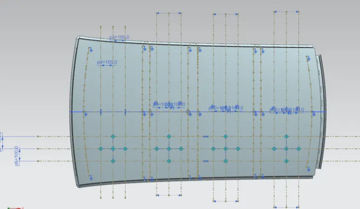
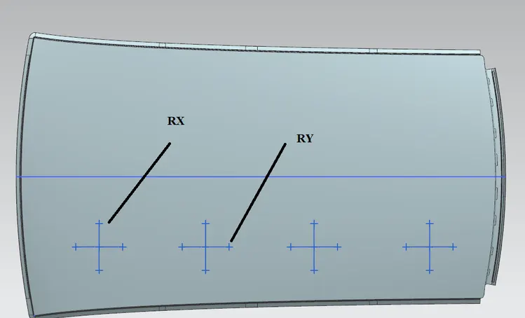
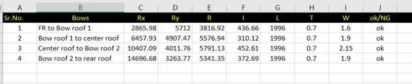
In order to avoid any bending or damages on the roof, heat distortion temperature can be recalculated using the trial and error method by changing the position of bow roofs. In this way, it can come in the range which is shown below.
Formula
W = [1.73 x 10^(-3) x L] + [1.85 x 10^(-8) x (R^2)/t] + [ 1.10x10^(-3) x l] - 2.68
Judgement Condition using w : OK< 2.7> 3.1
Where
L = Roof Length in X-Direction[mm](Roof dimension in 0-Y)
R = Roof curvature
R = 2(Rx*Ry)/(Rx+Ry)
Rx = X curvature
Ry = Y curvature
t = Roof plate thickness [mm]
l = Bow Roof Span [mm]
Annotations :-
Snowload Analysis :-
The purpose behind this analysis is to check the strength of the roof when snow is present on it acting as a load.
A roof should be designed in such a way that it should rebound to its original shape after the removal of snow.
Formula
Qr = [Iy x t2] / [α x s x [(Rx + Ry)/2]2 x 10-8]
Where
α = My x Lx2 x 10-12 , My = Y(Ly-Y)
Judgement condition = Qr ≥ 3.1
250 ≤ s ≤ 380
t = Roof plate thickness [mm]
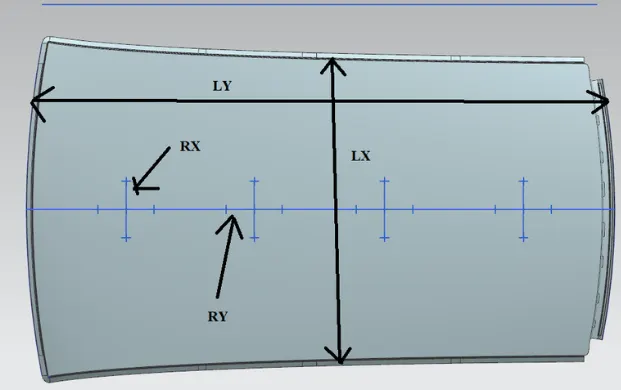
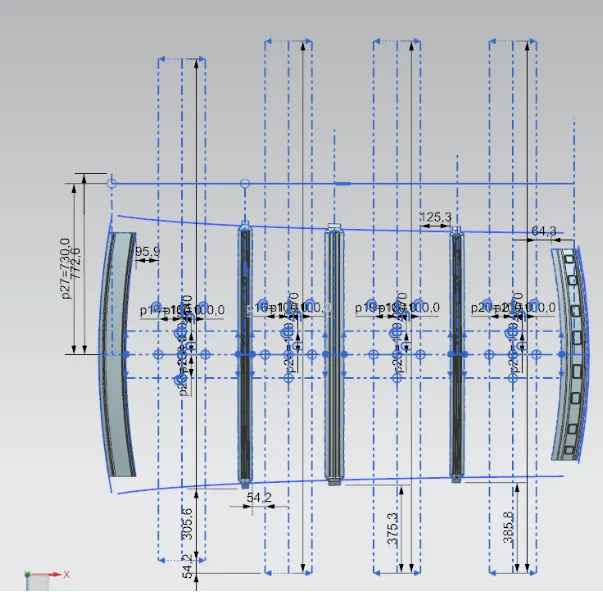
Ly = Distance between the front and rear roof Rails on the Vehicle along with 0Y[mm]
Length of Roof panel with the center point between Roof rail Front /Rear as the front and rear reference point.
Lx = Distance between the Left and Right end of the roof on the Roof BOW [mm]
Width of the roof panel exposed on the surface.
Y = Distance front Front Roof Rail to Roof BOW[mm]
s = Distance for which Roof BOW bears divided load [mm]
s = L1/2 + L2/2
Iy = Geometrical moment of inertia of Roof BOW (Y cross-section )[mm4]
Rx = Lateral direction curvature radius of roof panel Y cross-section on Roof BOW [mm]
Roof panel curvature Radius of the Length Lx in Front view
Ry = Longitudinal Direction curvature radius of the Roof panel X cross-section on Roof BOW [mm]
Roof panel X curvature radius of length s in Side view
Annotations :-

Draft Analysis :-
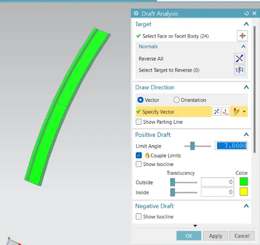
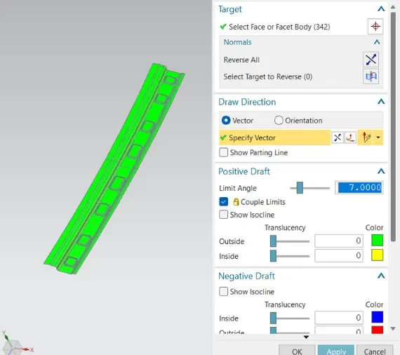
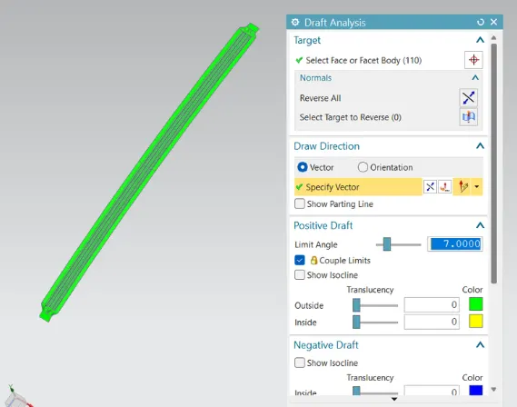
- All the faces of Front Roof Rail have successfully cleared the draft analysis with a minimum draft angle of 7 degrees.
RESULTS :-
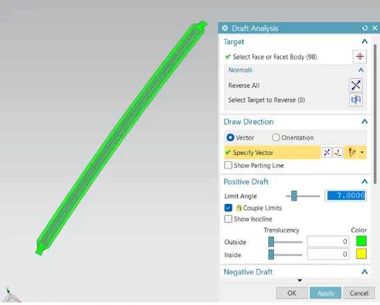
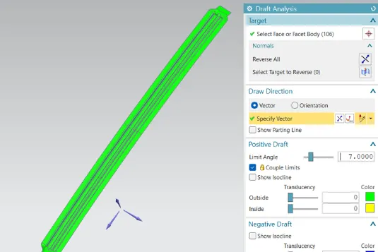
- All the parts have successfully cleared the draft analysis