Roof Crash Simulation
AIM:-To simulate the model to perform Roof crash and observing the deformations and plot the graphs for all the mentioned requests and energies.
OBJECTIVE:-
- To Check the unit system and either follow[Mg mm s] or [Kg mm ms].
- To translate the impactor to the desired location as per the question.
- To create a Type 7 contact interface between impactor and car.
- To create a boundary condition for the suspension shock tower and lock them in the Z direction.
- To create a moving SKEW to define the direction normal to the impactor.
- To create an impactor boundary condition.
- To apply an imposed displacement for the impactor.
- To create control cards.
- To set the termination time, nodal & element-time step.
- To request the output and run the simulation.
- To use model checker to ensure good quality.
- The simulations are run on hyper view for displacement and Von Mises.
- To plot the graphs by using hypergraph 2D for rigid wall forces, internal energy, hourglass energy, contact energy, and total energy.
- To plot the graphs by using hypergraph 2D for all the output requests.
- To plot the graphs by using hypergraph 2D for rigid wall forces, internal energy, hourglass energy, contact energy, and total energy individually for better understanding.
THEORETICAL EXPLANATION:-
- FMVSS 216, Roof Crush Resistance, establishes strength requirements for the passenger compartment roof of passenger cars, multipurpose passenger vehicles, trucks, and buses with a GVWR of 2722 kilograms or less. The purpose of the standard is to reduce deaths and injuries due to the crushing of the roof into the passenger compartment in rollover accidents.
- The prescribed static loading device is a rigid unyielding rectangular block 762 millimeters by 1,829 millimeters. It shall not move more than 127 millimeters to achieve the specified resistive load when applied to the forward edge of a vehicle’s roof.
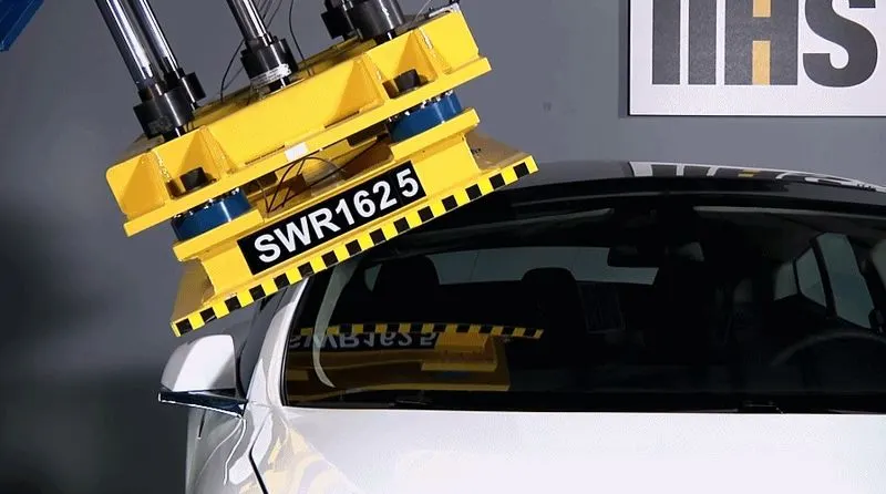
fig1.1
- The resistive load to be achieved is 1½ times the unloaded vehicle weight (UVW) of the test vehicle or 22,240 Newtons, whichever is less. Both the left and right front portions of the vehicle's roof structure shall be capable of meeting the requirements. The passenger car's sills shall be placed on a rigid horizontal surface and fixed rigidly in position. The vehicle's windows shall be closed and the doors shall be locked.
- This standard does not apply to school buses and passenger cars that conform to the dynamic rollover test requirements of FMVSS 208, Occupant Crash Protection, S5.3 by means that require no action by passenger car occupants. It also does not apply to convertibles, except for optional compliance with the standard as an alternative to the rollover test requirements in S5.3 of FMVSS 208.

fig1.2
PROCEDURE:-
*The model has been imported from downloads for both the impactor and Car BIW to hypermesh as shown in fig 1.3.
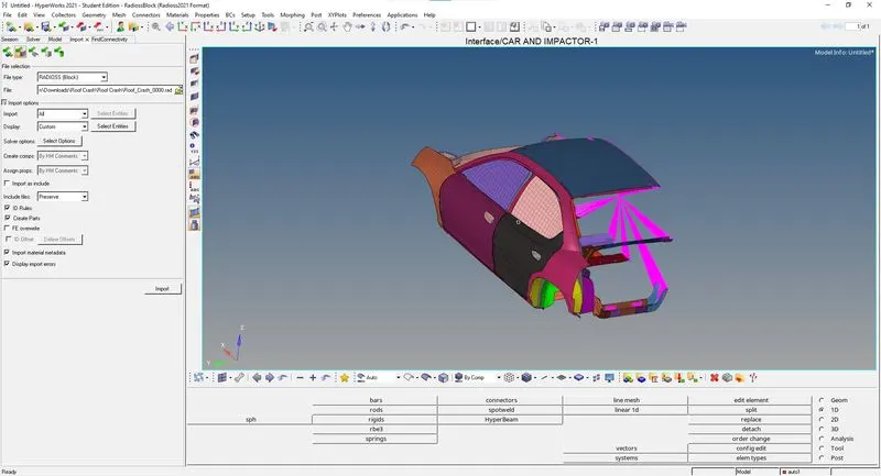
fig 1.3
*Since the Control cards are not existing the control cars are created for the required solver files as shown in fig 1.4a and fig 1.4b.

fig 1.4a
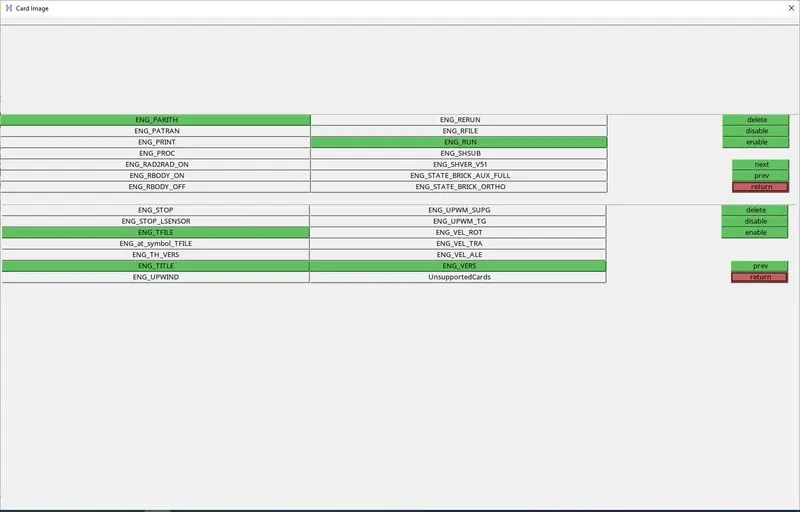
fig 1.4b
*The control card is created for the Spmd card and all required parameters have been updated as shown in fig 1.5.
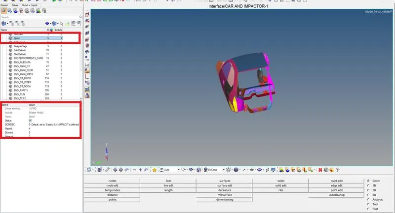
fig 1.5
*The control card is created for the IOflag card and all required parameters have been updated as shown in fig 1.6.
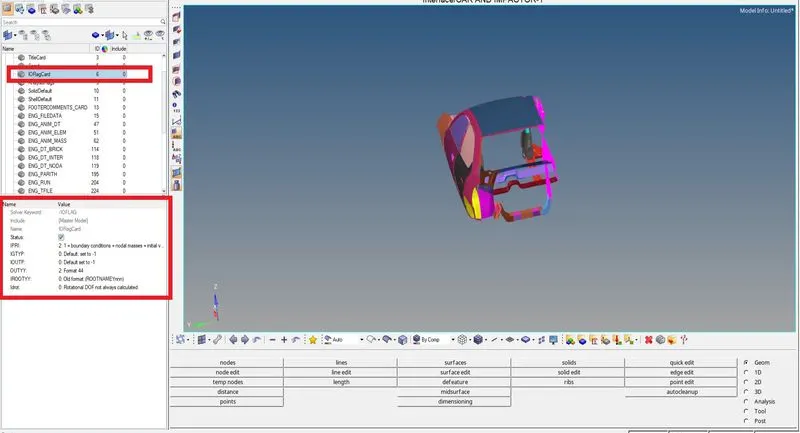
fig 1.6
*Include selected output in animation files from the ENG_AMIN_ELE as shown in fig 1.7.
• Elemental Energy
• Elemental equivalent plastic strain
• Elemental hourglass energy
• Elemental von Mises stress
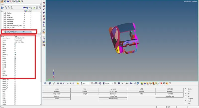
fig 1.7
*The control card is created for the PARITH card and all required parameters have been updated to Turn on parallel arithmetic as shown in fig 1.8.
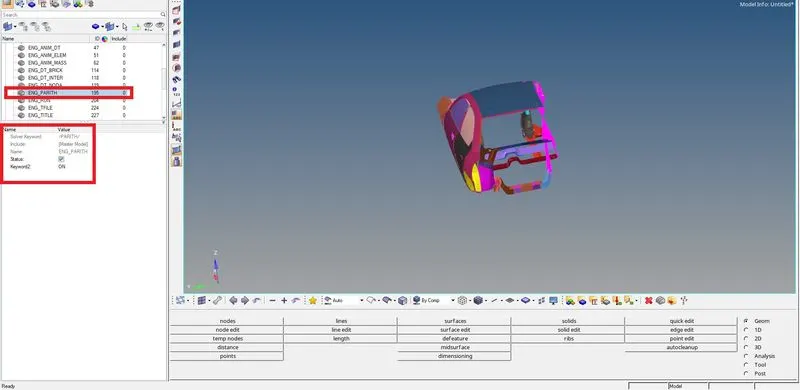
fig 1.8
*From the Eng_Run time is been updated as the mentioned 200 ms as shown in fig 1.9.
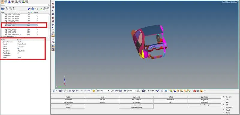
fig 1.9
*From the ENG_DT BRICK, ENG_DT INTER, ENG_DT NODA the time step is been updated as the mentioned 0.5 and 0.1 microseconds as shown in fig 1.10.
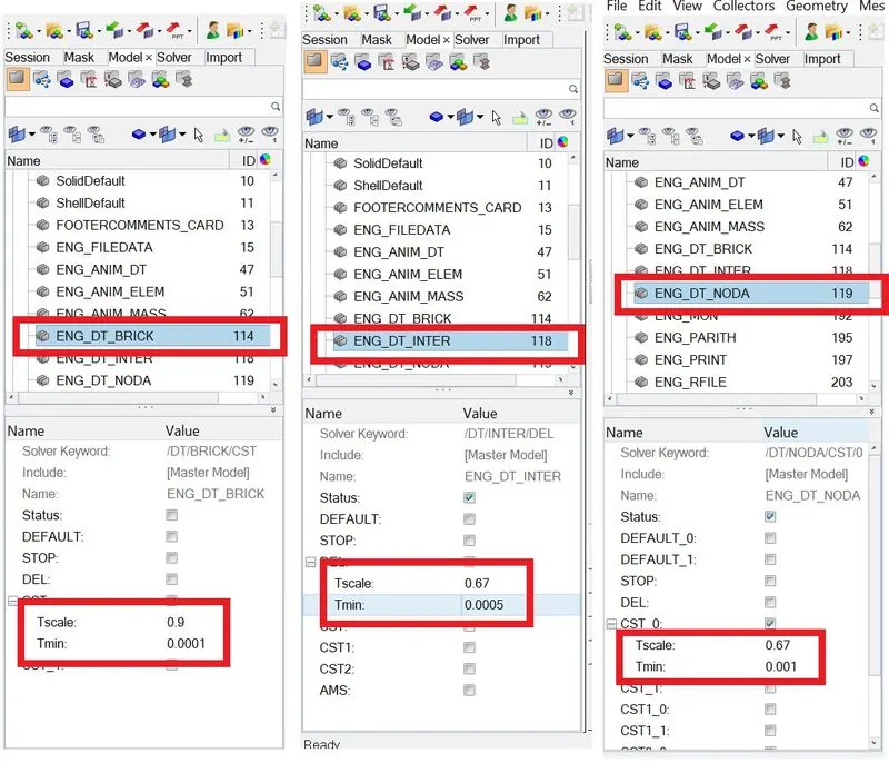
fig 1.10
*These are required steps to get the impactor from origin fig 1.11a to the B-Pillar adjacent to the roof fig1.11b.
• A 180° rotation about the global z-axis with the point opposite to C as a base point of the impactor.
• A 5° rotation about the axis through axis AB of the impactor.
• A 25° rotation about the axis through axis AC of the impactor.
• A translation to put point A at global ( -2100.00, 584.822, 1343.06).
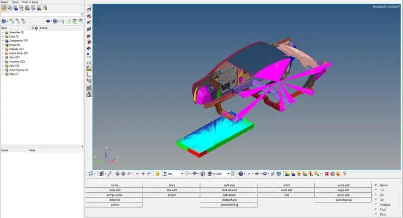
fig1.11a
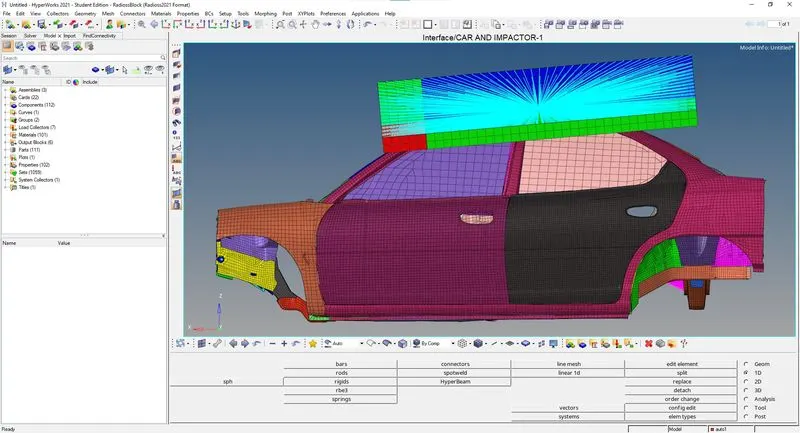
fig1.11b
*The contact group is created with a TYPE 7 and all required parameters have been updated as shown in fig 1.12.
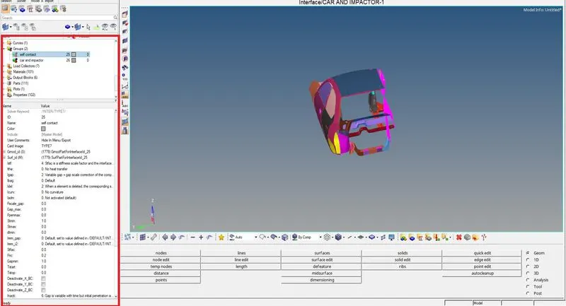
fig1.12
*The curve has been created for the initial displacement so we can add displacements to the impactor to cause an impact as shown in fig 1.13.
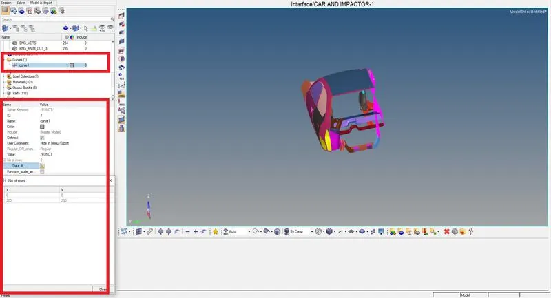
fig1.13
*The Initial displacement value is been added by selecting the create, boundary conditions,impdisp, and adding imposed displacement by selecting the curve created as shown in fig 1.14a and fig1.14b.
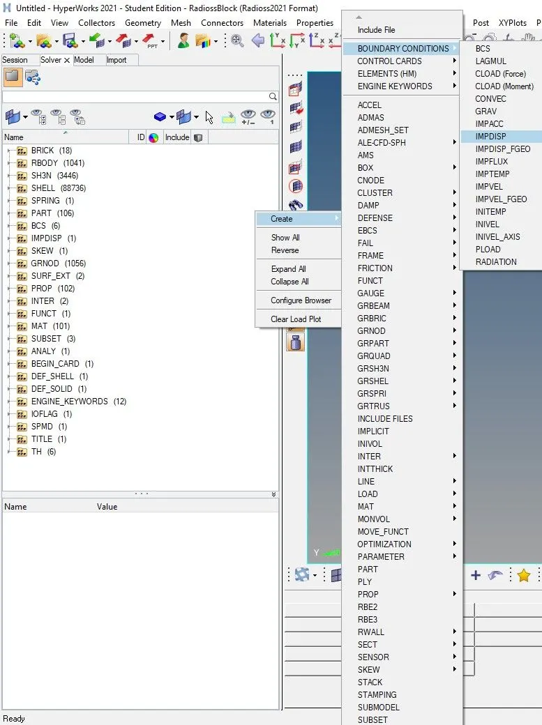
fig1.14a
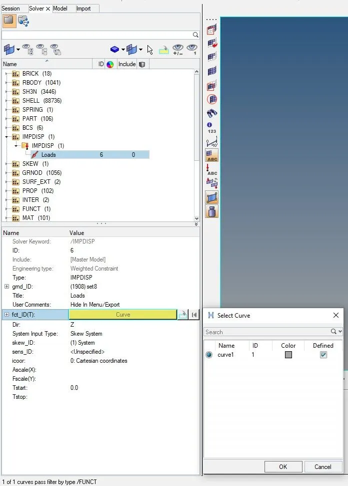
fig1.14b
*Boundary conditions are added to the suspension towers by locking the DOF in the Z direction with Rbody rigid elements as shown in fig1.15
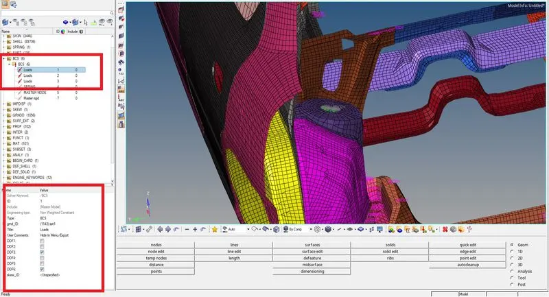
fig1.15
*Boundary conditions are added to the Impactor by locking all DOF except in Z direction translational with Rbody rigid elements as shown in fig1.16.
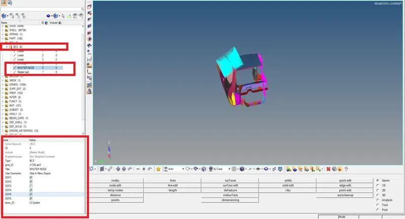
fig1.16
*Providing time history request for all the mentioned conditions for plotting of the graphs as shown in fig 1.17.
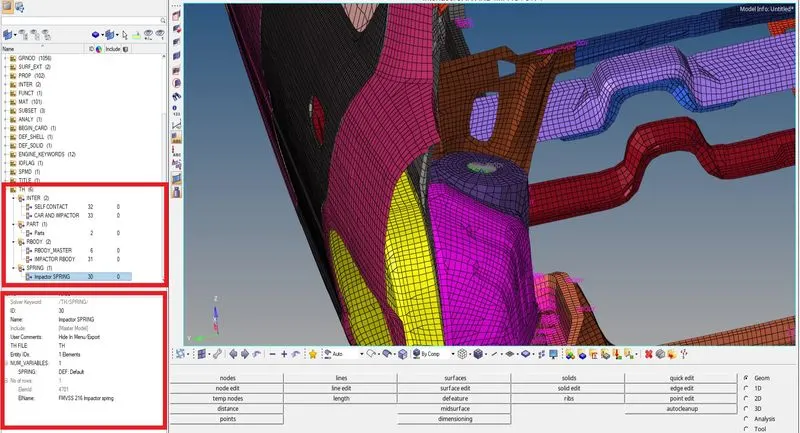
fig 1.17
* Checking for connectivity by selecting the Car BIW components and fixing connectivity by Creation of rigid body on the edge of both sides and both the free components by selecting at least 5 nodes on each free component as shown in fig 1.18a and 1.18b.
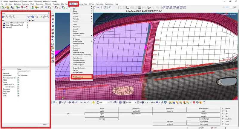
fig 1.18a
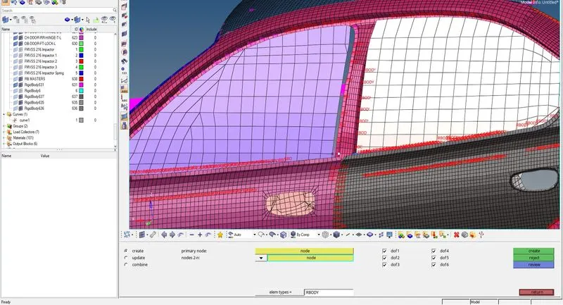
fig 1.18b
*The Model checker is run to check for any error, there were no errors so the model can be proceeded to run the simulations as shown in fig 1.19.
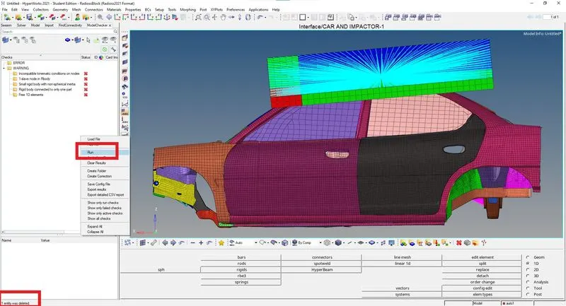
fig 1.19
*The simulations are run on hyper view for displacement and Von Mises and have been animated as shown in fig 1.20.
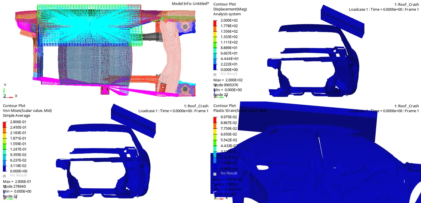
fig 1.20
*The graph is been plotted for the Impactor with Rigid body the max value of force among them is 18.0303 KN as shown in fig 1.21.
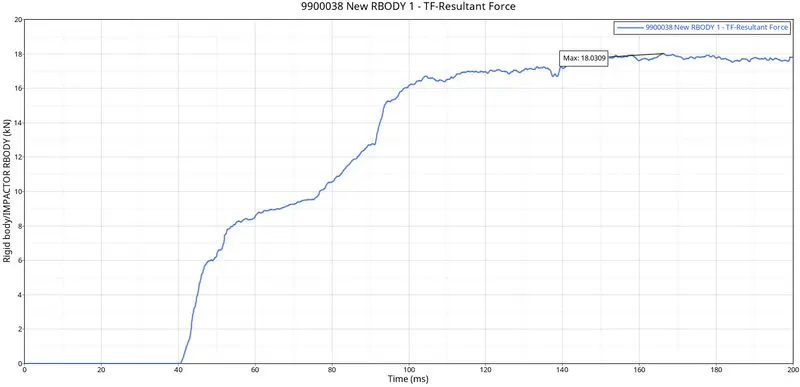
fig 1.21
*For the Displacement graph the plastic strain conture is created and a node is selected on the Roof towards the B-Pillar and the graph is been created for displacement as shown in fig 1.22a and 1.22b.
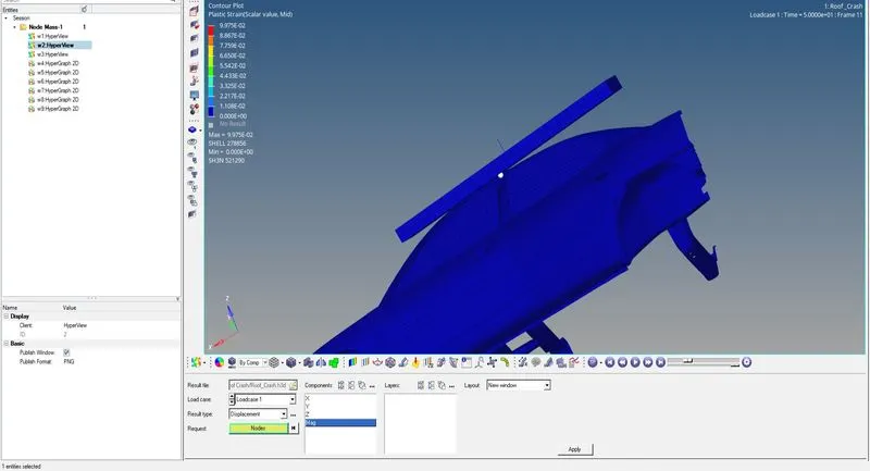
fig1.22a
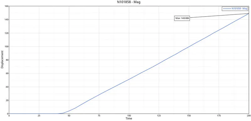
fig1.22b
*From the load the preference file is selected and vehicle safety tools are used for the access of the Math tool for cross plotting the graphs as shown in fig 1.23.
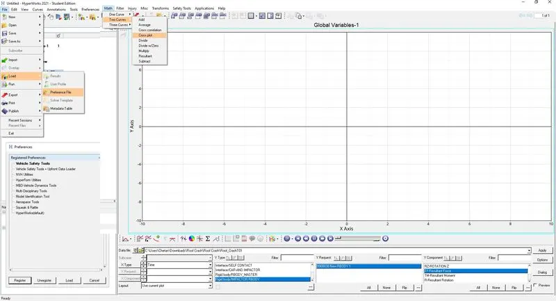
fig1.23
*The cross plot has been done between the force on the Y-axis and Displacement on the X-axis as shown in fig 1.24.
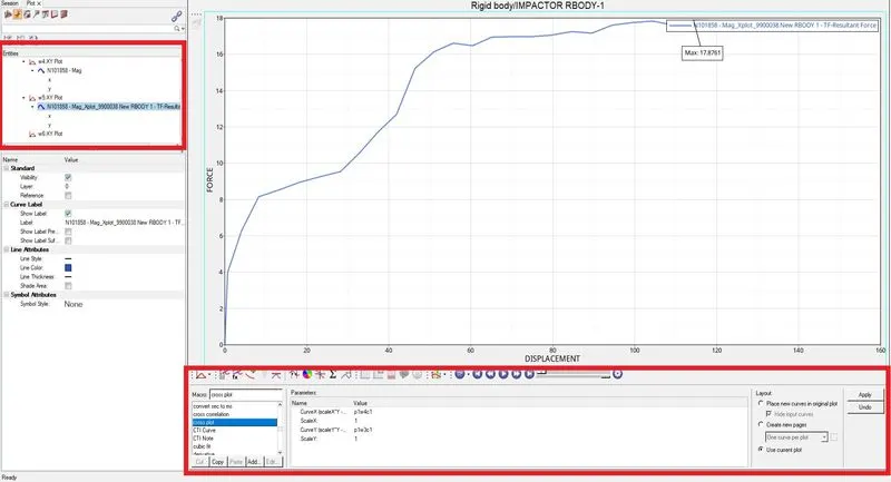
fig 1.24
*Hypergraph 2D mode is turned on and graphs have been plotted for Internal energy, Kinetic energy, Hourglass energy, Contact energy, and total energy graphs concerning global variables for Frontal Crash as shown in fig 1.25.
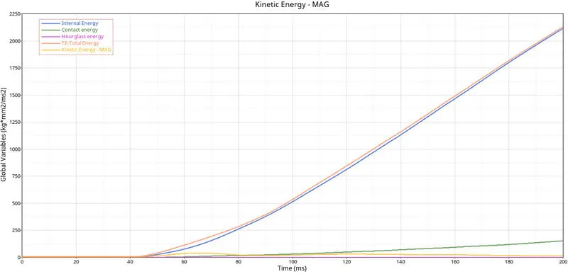
fig 1.25
*The internal energy starts from origin due to there being no contact between the Impactor and Car BIW. So the internal energy goes on increasing, proportionally the deformation or displacement is happening, when the displacement increases the internal energy increases as shown in fig1.26.
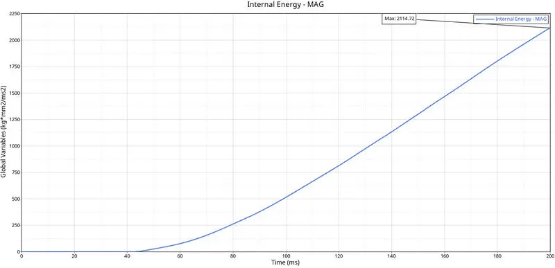
fig 1.26
* Kinetic energy is plotted for roof crush, the impactor will be moving it will be having some velocity. So due to some velocity, there will be kinetic energy. When the impactor hits the car model the energy will transfer to the model and the kinetic energy of the model gets increases the kinetic energy goes on increasing. as shown in fig 1.27.
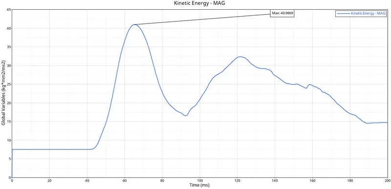
fig 1.27
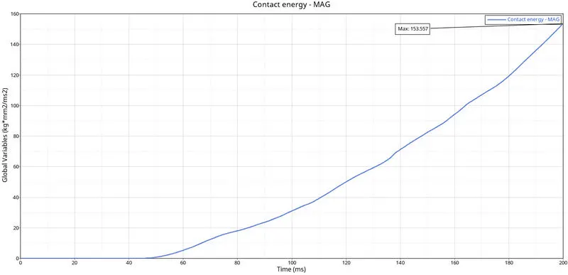
*At initial the there will be no impact so the Contact energy will be at zero and then as the deformation starts Contact energy increases gradually with respect to time. The graph has been plotted for Contact energy and time as parameters as shown in fig 1.28.
1.28
*The Hourglass energy is been occurred in the simulation the max value attained is 0.654Kg⋅mm2(ms)2Kg⋅mm2(ms)2. Which is below the permissible range that is less than 10% of the internal energy as shown in fig 1.29.
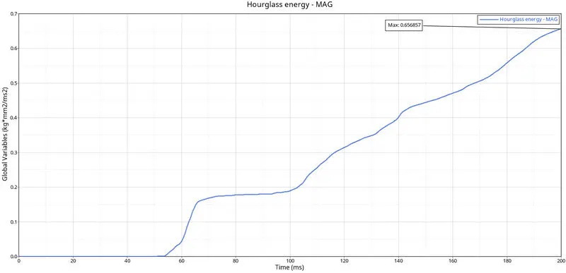
fig 1.29
*Since Total energy is the summation of all the energies so at the start there will only be Kinetic energy so the total energy will be equal until the deformation starts Total energy averages all energies with respect to time. The graph has been plotted for Total energy and time as parameters as shown in fig 1.30.
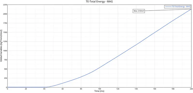
fig 1.30
*The graph is been plotted using the spring element Impactor spring with respect to time for total elongation in the spring elements in mm as shown in fig 1.31.
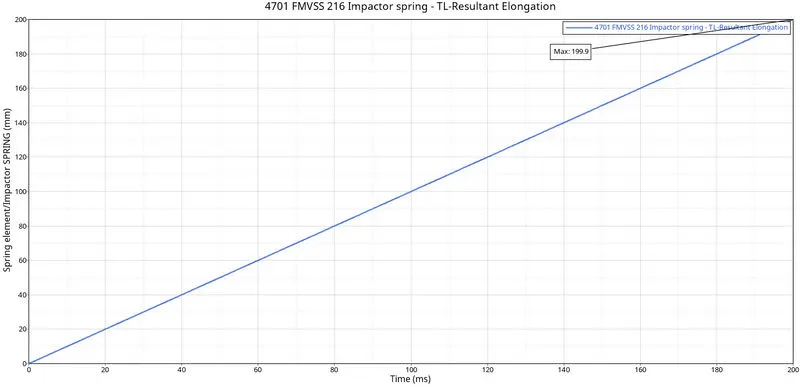
fig 1.31
*The graph is been plotted for the components with self contact with neighboring components for TYPE 7 contact the max value of force among them is 41.3615 Kg⋅mm(ms)2Kg⋅mm(ms)2 as shown in fig 1.32.
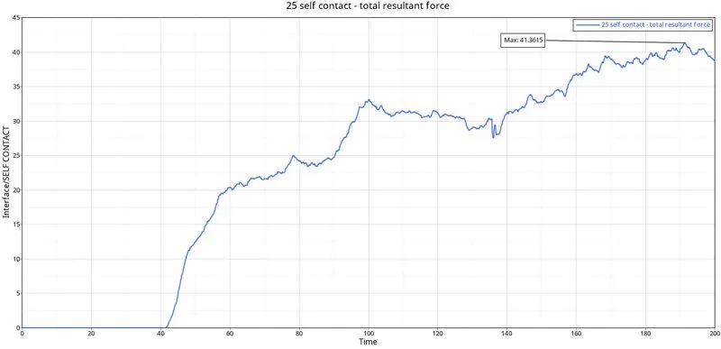
fig 1.32
*The graph is been plotted for the components with Car and Impactor for TYPE 7 contact the max value of force among them is 18.0313 Kg⋅mm(ms)2Kg⋅mm(ms)2 as shown in fig 1.33.
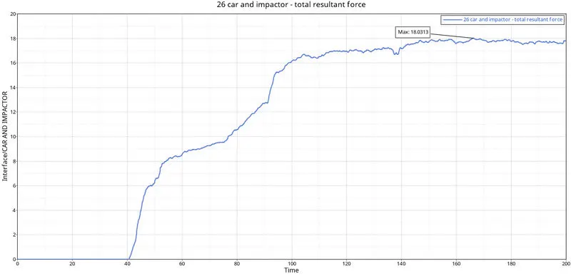
fig 1.33
*The graph is been plotted for the Rigid body created for the Suspension Towers the max value of force among them is shown in fig 1.34.
For Left Front Suspention Towers 9.48342 Kg⋅mm(ms)2Kg⋅mm(ms)2.
For Left Rear Suspention Towers 0.0063354 Kg⋅mm(ms)2Kg⋅mm(ms)2.
For Right Front Suspention Towers 0.0051375 Kg⋅mm(ms)2Kg⋅mm(ms)2.
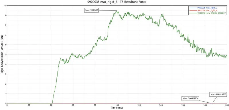
fig 1.34
*The graphs have been plotted by using hypergraph 2D for rigid wall forces, total resultant elongation for springs, contact forces, force vs displacement, internal energy, Kinetic energy, hourglass energy, contact energy, and total energy and are verified siminatusly as shown in fig 1.35.

fig 1.35
*For the Check that the FMVSS 216 target load of 47,000 N (= 3 * GVW) has been met or not the mass of the system is checked and calculated.
From fig 1.36, we can say the mass of the Car BIW is 142.6760
GVW=3⋅9.81⋅142.6760GVW=3⋅9.81⋅142.6760N
GVW=4,198.95468NGVW=4,198.95468N
The GVW of the simulated car is less target load of 47,000 N for FMVSS 216.
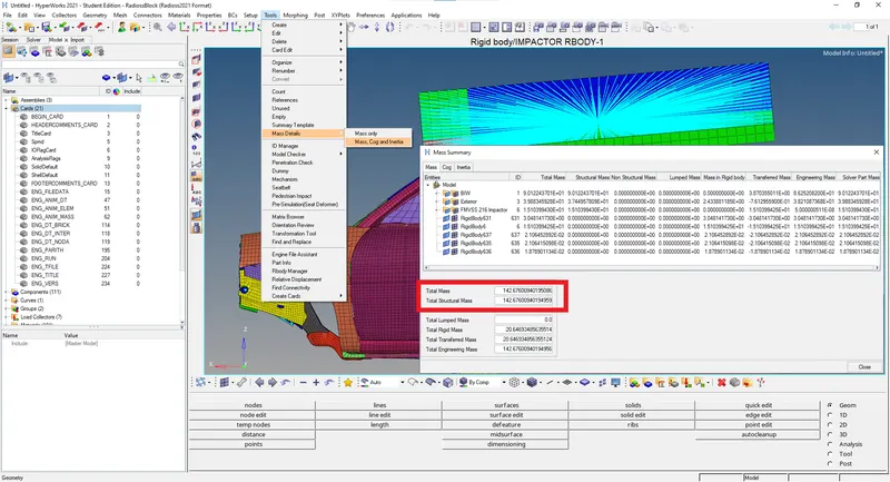
fig 1.36.
RESULT:-The model was simulated to perform the Roof crash test and observed the deformations and plotting of the graphs for all the mentioned requests, Cross plots, Check for GVW and energies.