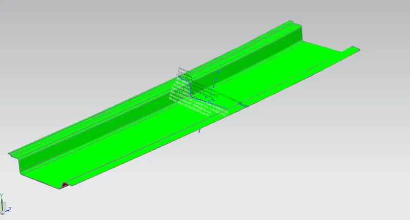
Roof challenge
AIM:
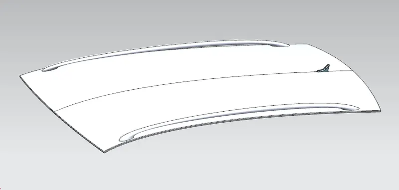
For the given roof styling, Develop the essential flanges and reinforcements, provide appropriate dimensions and check for draft analysis, and submit the section inertia report on the O-Y section.
OBJECTIVE:
- Develop essential flanges and reinforcements for the roof design
- Create an assembly file for the developed roof design with reinforcements and flanges
- Calcuate the section modulus of the roof design and assembly
- Check the draft analysis of entire roof design
OBSERVATION:
A roof structure for an automotive vehicle with a reinforcement for a roof panel is especially applicable for the vehicle having a sun-roof. Longitudinal reinforcement for the roof panel is provided by one or more pressed reinforcement ribs formed in the roof panel and extending parallel to the longitudinal axis of the vehicle. Each reinforcement rib has a front end located near the rear lateral edge of the sun-roof. A stiffener extends perpendicular to the axis of the reinforcement ribs and lies across the front ends of the reinforcement ribs for reinforcing the front ends at which bending stresses tend to concentrate.
The curvature study on the roof and perform calculations to determine the position of the Bow-roof.
Bow–roof prediction Formula
W = [1.73 x 10^(-3) x L] + [1.85 x 10^(-8) x (R^2)/t] + [ 1.10x10^(-3) x l] - 2.68
Judgement Condition : OK< 2.7> 3.1
Where
L = Roof Length in X-Direction[mm](Roof dimension in 0-Y)
R = Roof curvature
R = 2(Rx*Ry)/(Rx+Ry)
Rx = X curvature
Ry = Y curvature
t = Roof plate thickness [mm]
l = Bow Roof Span [mm]
Snow load Prediction formula
Qr = [Iy x t2] / [α x s x [(Rx + Ry)/2]2 x 10-8]
Note: The Qr value given over here is correct. There was a typo error in the formula given in the video.
Where
α = My x Lx2 x 10-12 , My = Y(Ly-Y)
Judgement condition = Qr ≥ 3.1
250 ≤ s ≤ 380
t = Roof plate thickness [mm]
Ly = Distance between the front and rear roof Rails on the Vehicle along with 0Y[mm]
Length of Roof panel with the center point between Roof rail Front /Rear as the front and rear reference point.
Lx = Distance between the Left and Right end of the roof on the Roof BOW [mm]
Width of the roof panel exposed on the surface.
Y = Distance front Front Roof Rail to Roof BOW[mm]
s = Distance for which Roof BOW bears divided load [mm]
s = L1/2 + L2/2
Iy = Geometrical moment of inertia of Roof BOW (Y cross-section )[mm4]
Rx = Lateral direction curvature radius of roof panel Y cross-section on Roof BOW [mm]
Roof panel curvature Radius of the Length Lx in Front view
Ry = Longitudinal Direction curvature radius of the Roof panel X cross-section on Roof BOW [mm]
Roof panel X curvature radius of length s in Side view
PROCEDURE:
Develop essential flanges and reinforcements for the roof design
Step-1: Create front flange and ditch area
- Create a front flange using offset surface and law extension command for the given dimensions
- Then create a ditch area for the given desired value.
- Use bridge curve and trim sheet option to get a curved edge of 5mm.
- And also use face blend option to avoid sharp edges.
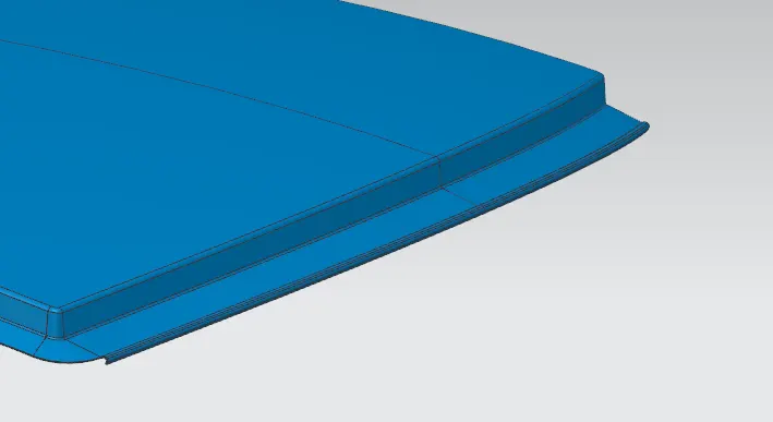
Step-2: Create rear flanges
- Create a rear flange using offset surface and law extension command for the given dimensions.
- Use bridge curve and trim sheet option to get a curved edge of 5mm.
- And also use face blend option to avoid sharp edges.
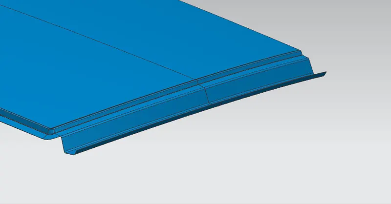
Step-3: Create side flanges
- Create side flange using offset surface and law extension command for the given dimensions.
- And also use face blend option to avoid sharp edges.
- To join all the flanges use bridge curve and studio surfaces option.
- After connecting the flanges together mirror them, sew them and thicken it for 0.75mm.
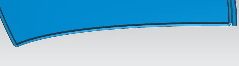
Step-4: Design front roof rail
- Use the offset surface option from roof model and front flanges for the desired dimensions given.
- Extend the surface for 10 mm.
- Then use law extension command to join the surfaces together.
- For the next half portion use offset curve in surface command and give the dimensions as on model image.
- Use the trim sheet option to cut off the unnecessary extensions. If any error occurs to recognise the curve boundary extend the curve in length.
- Use through curve option to join all the trimed sheets and use face blend to make curved edges.
- After connecting the sheets together mirror them, sew them and thicken it for 0.75mm.
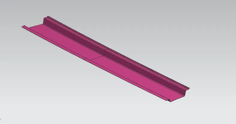
Step-5: Design rear roof rail
- Follow the same procedure delivered to the front roof rail.
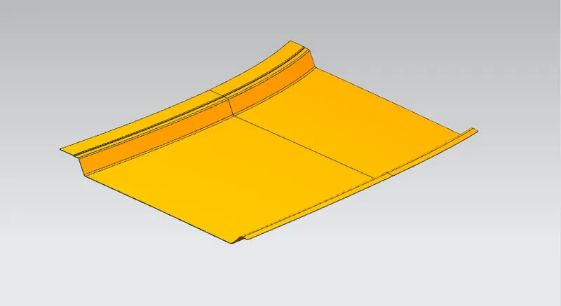
Step-6: Design bow roof
- Use the offset surface option from roof model for the desired dimensions given.
- Use offset curve in surface command for the desired dimensions.
- Use the trim sheet option to cut off the unnecessary extensions. If any error occurs to recognise the curve boundary extend the curve in length.
- Use through curve option to join all the trimed sheets and use face blend to make curved edges.
- Then offset the side flanges for the given allowances.
- And trim its edges using datum plane and trim sheet option.
- Attach the trimmed edges to the bow roof design using swept option along with bridge curve.
- After connecting the sheets together mirror them, sew them and thicken it for 0.75mm.
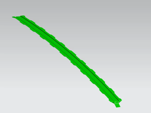
- A roof contains two or more bow roof attachments make sure there is atleast two bow roof by adding it to the roof assembly.
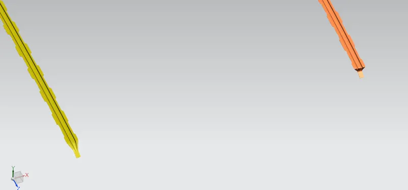
Step-7: Design reinforcement center
- It also follows the same procedure as bow roof except its position and dimensions differ.
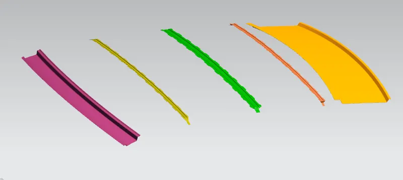
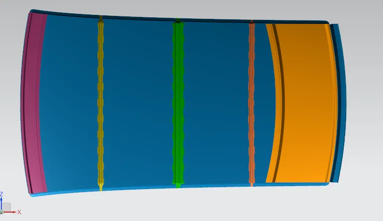
Create an assembly file for the developed roof design with reinforcements and flanges
- Assembling all the parts together in separate file using add components with desired datum coordinates.
- Give a constraint as touch align and save it.
Analysis
- Bow–roof prediction Formula
W = [1.73 x 10^(-3) x L] + [1.85 x 10^(-8) x (R^2)/t] + [ 1.10x10^(-3) x l] - 2.68
Judgement Condition : OK< 2.7> 3.1
Where
L = Roof Length in X-Direction[mm](Roof dimension in 0-Y)
R = Roof curvature
R = 2(Rx*Ry)/(Rx+Ry)
Rx = X curvature
Ry = Y curvature
t = Roof plate thickness [mm]
l = Bow Roof Span [mm]
- Create a sketch by creating lines of the bisectional lines of each part to derive a four region of Rx and Ry lines to get its values.
- Project the line over the roof and measure the radius of curvature using local radius command.
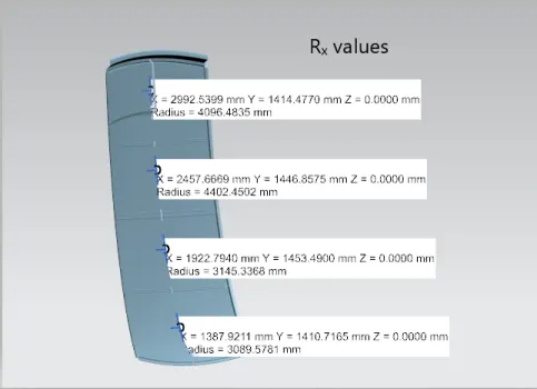
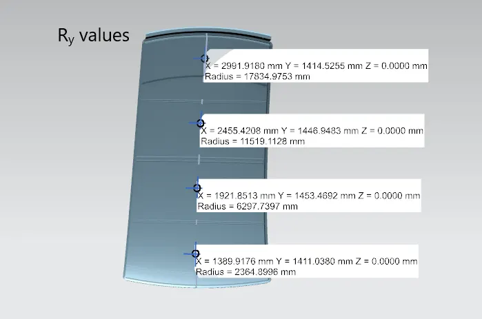
| S.NO. | BOW | Rx(mm) | Ry(mm) | R(mm) | l(mm) | L(mm) | R^2/t(mm) | t(mm) | W(mm) | Status |
| 1 | FR & 1st | 3089.5781 | 2364.8996 | 2679.0987 | 415.093 | 2030.2948 | 53831.7738 | 0.75 | 1.29 | OK |
| 2 | 1st & CTR | 3145.3368 | 6297.7397 | 4195.3514 | 335.581 | 2030.2948 | 23467964.4926 | 0.75 | 1.636 | OK |
| 3 | CTR & 2nd | 4402.4502 | 11519.1128 | 6370.2691 | 424.566 | 2030.2948 | 54107104.5419 | 0.75 | 2.3 | OK |
| 4 | 2nd & RR | 4096.4835 | 17834.9753 | 6662.6377 | 382.651 | 2030.2948 | 59187654.8286 | 0.75 | 2.348 | OK |
-
Snow load Prediction formula
Qr = [Iy x t2] / [α x s x [(Rx + Ry)/2]2 x 10-8]
Note: The Qr value given over here is correct. There was a typo error in the formula given in the video.
Where
α = My x Lx2 x 10-12 , My = Y(Ly-Y)
Judgement condition = Qr ≥ 3.1
250 ≤ s ≤ 380
t = Roof plate thickness [mm]
Ly = Distance between the front and rear roof Rails on the Vehicle along with 0Y[mm]
Length of Roof panel with the center point between Roof rail Front /Rear as the front and rear reference point.
Lx = Distance between the Left and Right end of the roof on the Roof BOW [mm]
Width of the roof panel exposed on the surface.
Y = Distance front Front Roof Rail to Roof BOW[mm]
s = Distance for which Roof BOW bears divided load [mm]
s = L1/2 + L2/2
Iy = Geometrical moment of inertia of Roof BOW (Y cross-section )[mm4]
Rx = Lateral direction curvature radius of roof panel Y cross-section on Roof BOW [mm]
Roof panel curvature Radius of the Length Lx in Front view
Ry = Longitudinal Direction curvature radius of the Roof panel X cross-section on Roof BOW [mm]
Roof panel X curvature radius of length s in Side view
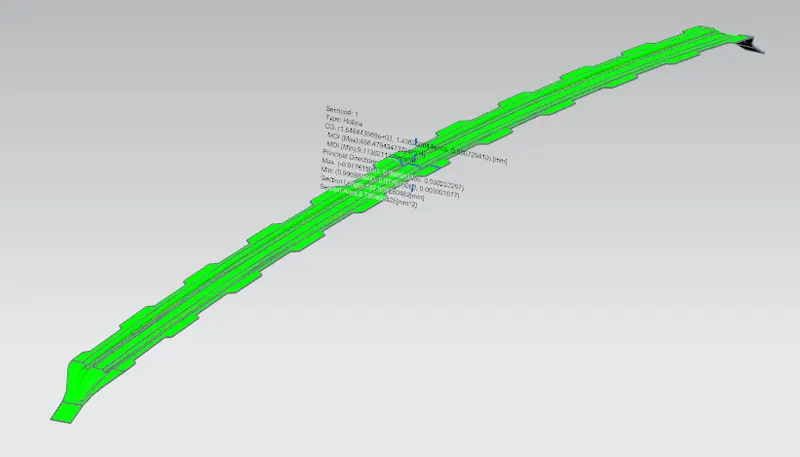
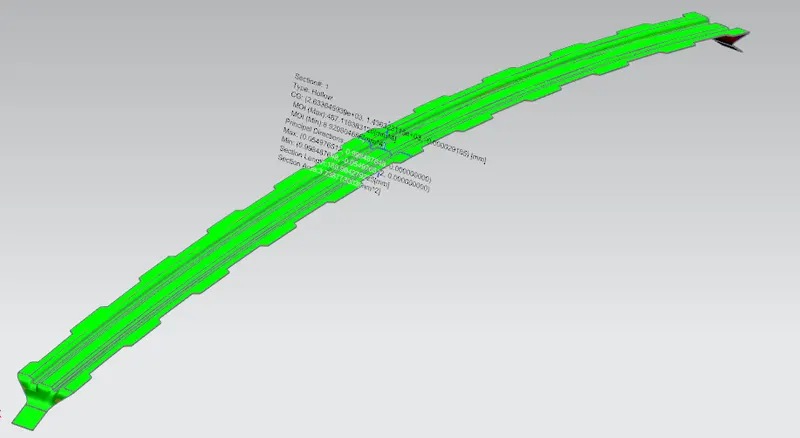
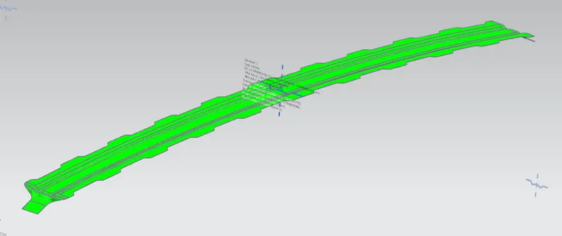
- Create section curve for the thicken body and execute sectional inertia analysis option and select the sectional curve
- Follow the same procedure for 2nd bow roof, center reinforcement and front, rear roof rails
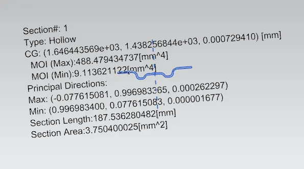
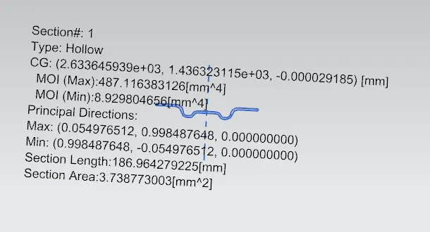
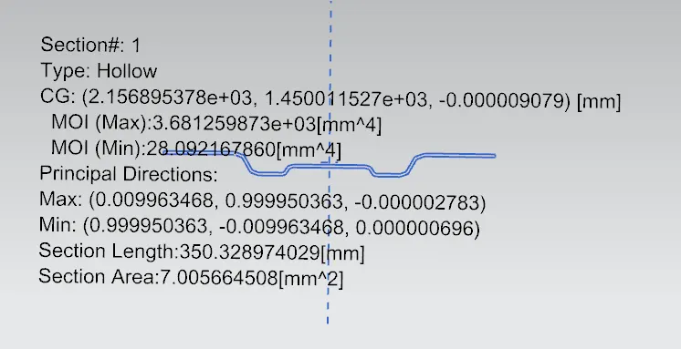
| S.NO. | BOW | Rx(mm) | Ry(mm) | Iy(mm) | a(mm) | Lx(mm) | Ly(mm) | y(mm) | t(mm) | s(mm) | Qr | Status |
| 1 | FR & 1st | 4089.5781 | 2364.8996 | 488.48 | 0.902 | 1193.6623 | 2030.2948 | 384.51 | 0.75 | 440.398 | 6.64 | OK |
| 2 | 1st & CTR | 3845.3368 | 6297.7397 | 487.12 | 0.9756 | 1132.0405 | 2030.2948 | 496.2862 | 0.75 | 480.45 | 11.07 | OK |
| 3 | CTR & 2nd | 4402.4502 | 11519.1128 | 368.13 | 0.879 | 1099.3217 | 2030.2948 | 464.61 | 0.75 | 414.2 | 8.97 | OK |
| 4 | 2nd & RR | 4096.4835 | 17834.9753 | - | 0.719 | 1089.1715 | 2030.2948 | 363.833 | 0.75 | - | - | - |
Check the draft analysis of entire roof design