Roof challenge
Title of the project: Roof Design
Aim: To design the roof of the car along its components by following the master section and design parameters.
Objectives:
- To design the essential flanges ( i.e. Ditch Area ) and the reinforcement using roof styling as input.
- To determine the heat distortion criteria test of the roof.
- To determine the snow load criteria test of the roof
- To perform draft analysis for manufacturability.
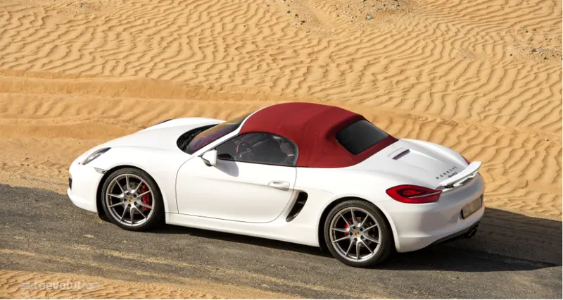
Introduction: Roof of a car is the portion of an automobile that sits above the passenger compartment. It protects the vehicle occupants from sun, wind, rain and other external elements.
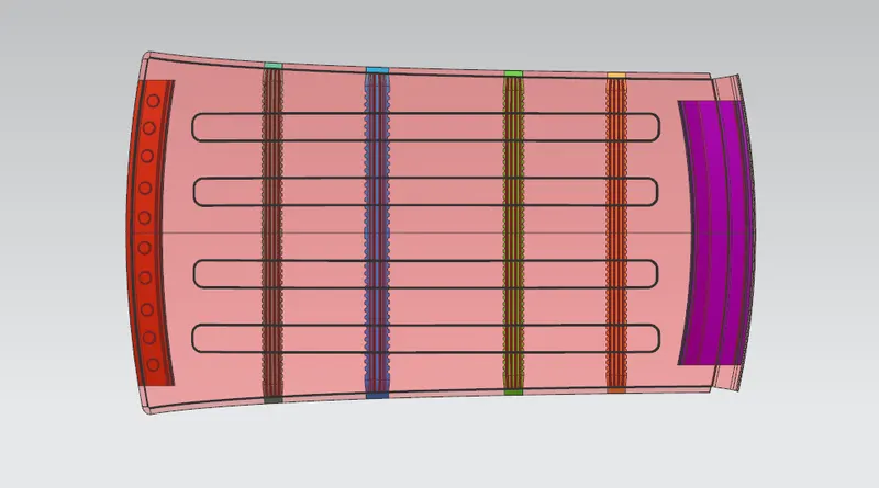
Types of roof
- Hardtop
- Sunroof
- Convertibles
Hardtop:
A hardtop is a rigid types of automobile roof, which for modern car is typically constructed from metals. A hardtop roof s can either be fixed (i.e. not removable), detachable for separate storing or retractable within the vehicle itself.

Sunroof:
A sunroof is an operable type of roof that allows for an opening in the roof of an automobile; say a window in a roof. It can allow either light or air or both to enter the vehicle. They are either operated manually or automatically.
There are three types of sunroof. They include:
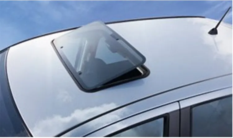
a. Pup-up:
The pup-up sunroof usually tilts when we open it. It is the most basic and relatively cheaper type of sunroof. Some can even be removed so that they are kept properly, may be in the trunk whenever we want to go ‘sunroof mode’.
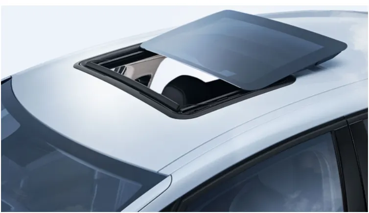
Spoiler:
The spoiler is a pup-up that would slide, instead of tilting upwards. The advantage of this is that it can easily be restored to its original position by sliding.
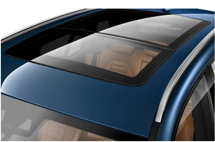
c. Panoramic sunroof:
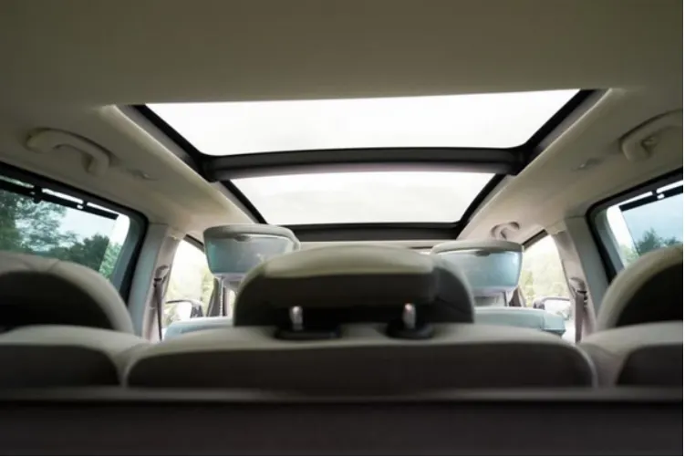
Panoramic sunroofs are distinct. While other sunroofs basically allow air and light or both into the front seats, the panoramic sunroof would allow for both the front and rear. This means the aperture would be larger than the spoiler or pop-up.
Convertibles:
Convertibles are passenger cars that can be driven with or without the entire roof in place. They were first introduced as open air-vehicles; no roofs, no sides.
But by the end of the 19th century and the early 20th century, car engineers built more powerful engines that could power a folding roof. These were the forerunners of the convertibles that we have today.
There are different types of convertibles based on the method of conversion and material used. They are:
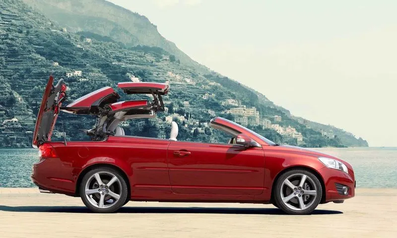
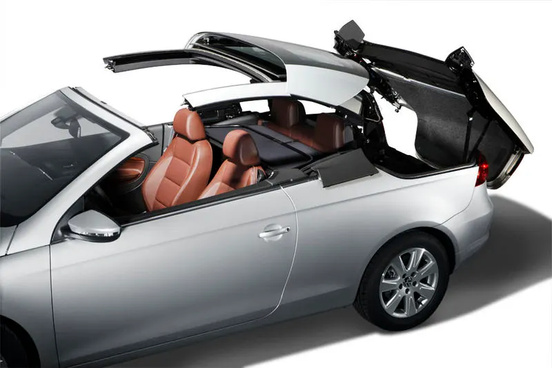
a. Retractable hardtop:
Made from metal or plastic and is retracted automatically.
b. Detachable hardtops:
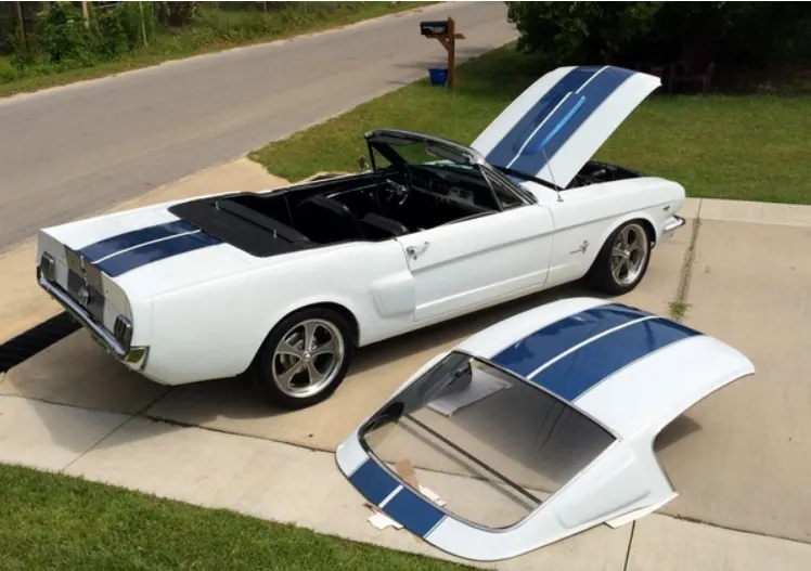
This type of hardtop is manually removed from the roof and then stored usually in the trunk. They are also made from metal or plastic.
c. Soft tops:
This types of convertibles have roof that are made from metal or plastic. They are made of textile. The earliest version of the convertible used canvas for the roofs. More recent models use cloth material instead. Other material used now include latex, vinyl, polyvinyl chloride.
When roof is folded it is called a stack.
Components of a roof:
Roof Outer Panel and Ditch Area:
Roof outer panel is made of sheet of at least 0.75 mm which protects the cabin from external conditions and objects. The ditch area is the extended portion of the main roof concealed by the other BIW panels. The rail support of the roof are attached to the ditch area using spot welds. Some of the factors considered while designing ditch area are Headroom clearance, visibility criteria, clearance for wind shield and back door.
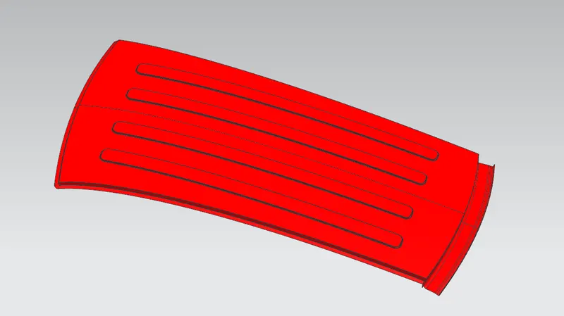
Front Roof Rail
It lies at the frot part of the roof. It provides strength to the roof panel front. It is the support which is joined with the wind shield glass, body side outer and the inner panels. The draft angle of 3-5 degrees is provided keeping in mind of deep drawing operation. The bottom most flange is designed by considering the head room clearance and visibility criteria. Spot welds are applied at wind shield end of the rail and the other end is joined with the roof using mastic sealants which also contributes to increase strength.
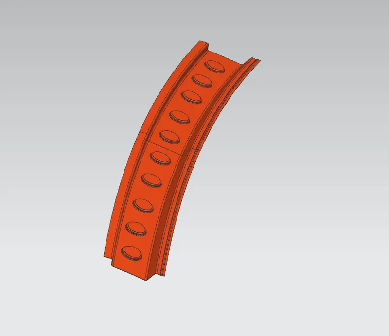
Rear Roof rail
It lies at the rear part of the roof. It provides strength to the roof panel rear. It is the support which is joined with the back door, body side outer and inner panels. The design consideration is same as of the front roof rail but here inputs from the back door design is also taken into consideration to accommodate the required clearance. Spot welds are applied at the back door end of the rail and the other end is joined with the roof using mastic sealants.
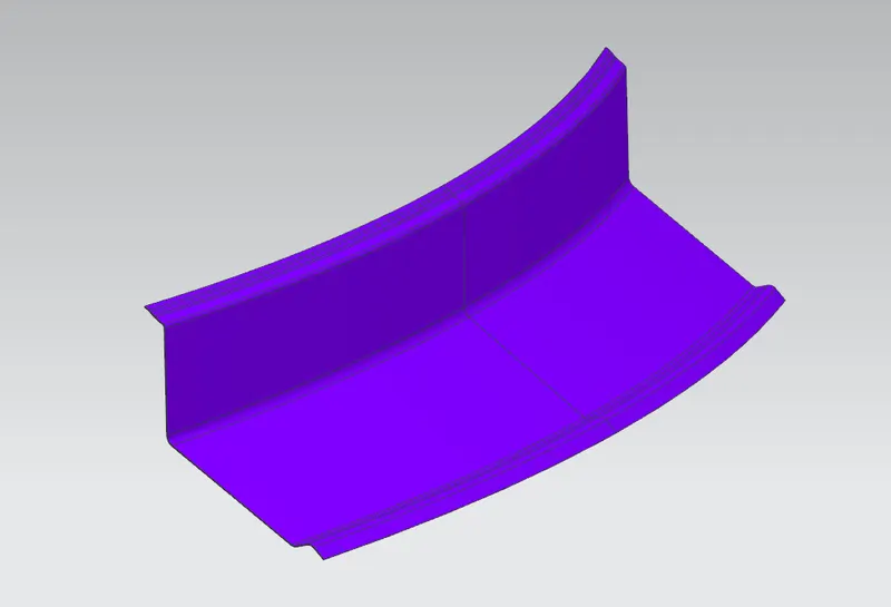
Reinforcement Roof Center:
This is the roof rail that lies between the B-pillar of the car and provides support to the center of the roof. They are usually 1-2 mm thick which provides a support area for the center cabin light mount. While designing the head room clearance and visibility criteria is taken into consideration. The roof is fixed to the roof rails with the use of mastics and the ends are spot welded.
Bow Roof Rails:
The bow roof rails provide additional support to the roof. They are positioned in such a way that they provide maximum support to the roof. They are designed in such a way that they donot intrude into the head room requirement of the car. Bow roof rails are the additional features provided as per the requirement. Small cars may have no bow roof while the large cars may have 2 or more. If there is the sunroof then bow roof are integrated into the center roof rail. The roof is fixed to the bow roofs with the use of mastics while the ends are spot welded.
Bow roof 1
Bow roof 2
Bow roof 3
Design of Roof:
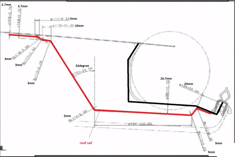
Master section
Front section
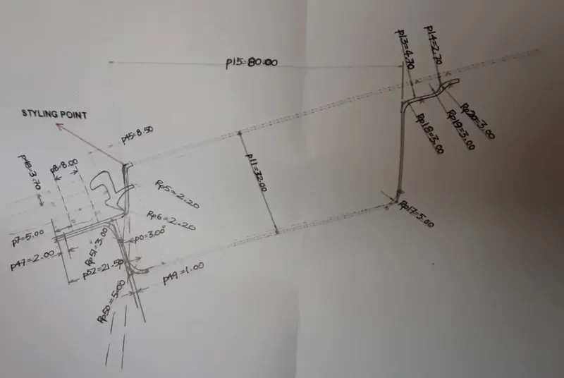
Rear section
Styling surface as input
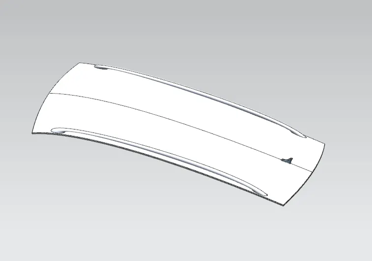
The front roof rail and the rear roof rail are designed by follwing these master sections and by extracting this styling surface where as the bow roofs and the center roof rail are designed by considering the engineering parameters.
Design Consideration for roof:
- Visibility criteria
- Headroom Clearance
- Curvature study
- Heat distortion test
- Snow load test
- Draft analysis
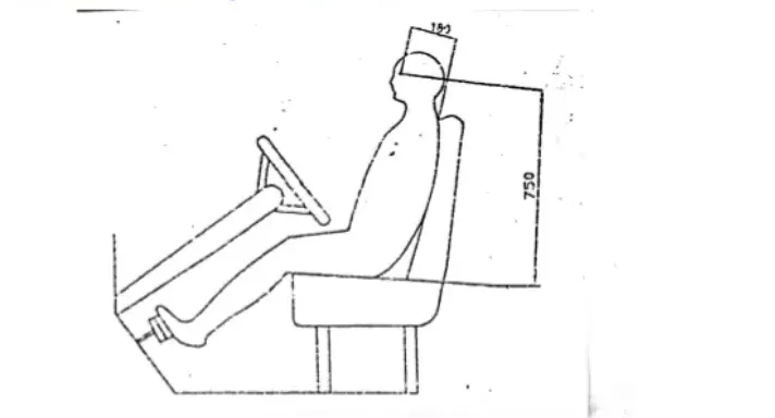
Visibility:
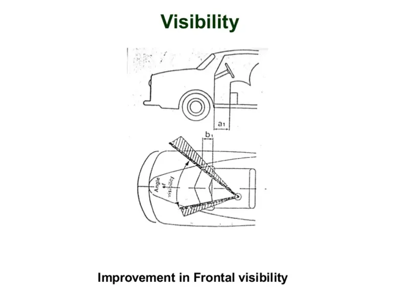
Good all round visibility is one of the main requirements of body design. Visibilty depends on the window opening and their relative position to the occupants. If occupant is placed close to wind screen the forward visibility is considerably improved but comfortable entry is adversely affected as dimention between pillar and seat is decreased requiring suitable shaping of the door, if possible.Downward visibility can be improved by positioning the driver as high as possible in realation to the lower edge of wind screen. Rearward visibility is achieved by increase in glass area required to maintain rear view vertical angle with back window. Figures below show eye position of driver, angle of visibilty and space between pillar and seat.
Headroom clearance:
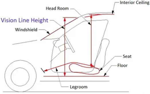
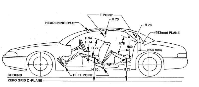
Headroom is measured as the distance from a car’s roof to its seat bottom. A more appropriate name might be ‘torso room’. Sometimes there is maximum and minimum values published, since most cars have seats that adjust up and down.
Roof Crush Test:
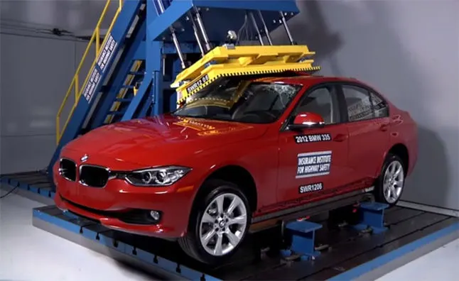
Roof crush is the failure and the displacement of an automobile roof into the passenger compartment during a rollover accident. To avoid this the Insurance Institute of Highway Safety introduce this ‘Roof crush test’. So after analysing so many accidents IIHS has then fixed some regulation how to perform the roof crush test.
Purpose of doing roof crush test:
Roof crush test is done to minimize the protrusion into the occupant compartment so that the seat belts and air bags can do their work properly. Features such as electronic stability control are proven to significantly reduce rollovers and lane departure warning systems may also help. Rollover sensing side curtain airbags also help to minimize injuries in the event of a rollover.
Conditions for roof crush test:
There are two conditions that are followed in the roof crush test. They are;
First condition:
- Close and lock all the doors
- Close all the windows
Second condition:
Fix the body sill or chassis frame on a hard lever surface horizontally
Method of applying force:
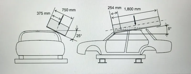
The load is applied in such a way that 5˚ is tilted to the front end from the rear end and the the load will be applied in the 1800 mm in length and 750 mm in width. The load is applied at the position of 25˚ from the flatness of the roof downward to the rightside. The load is applied on the roof for almost 120 seconds and the the crush speed is 13mm/sec or less than that at which the load is applied.
Test results and improvement:
If the displacement goes above the requirement level then we have to increase the bow roof thickness or add more mastic points and embosses to increase the strength. The stronger the roof the better it can protect the occupants in the rollover crashes.
Heat distortion criteria:
Heat distortion temperature is the temperature at which materials soften and deforms under a specific load. This study is used to predict the heat distortion temoerature at where the materials start to soften when exposed to a fixed load at elevated temperature. In order to avoid bending or damages on the roof, base don heat distortion temperature, this study will predict the bow roof position which help to strengthen the roof.
Bow–roof prediction Formula
W = [1.73 x 10^(-3) x L] + [1.85 x 10^(-8) x (R^2)/t] + [ 1.10x10^(-3) x l] - 2.68
Judgement Condition : OK< 2.7> 3.1
Where,
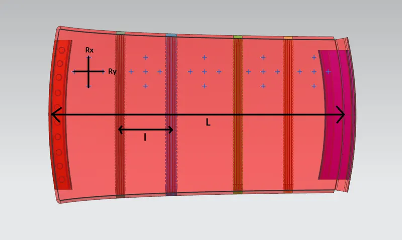
L = Roof Length in X-Direction [mm] (Roof dimension in 0-Y)
R = Roof curvature = 2(Rx*Ry)/(Rx+Ry)
Rx = X-curvature
Ry = Y-curvature
t = Roof plate thickness [mm]
l = Bow Roof span [mm]
Input data:
Calculation:
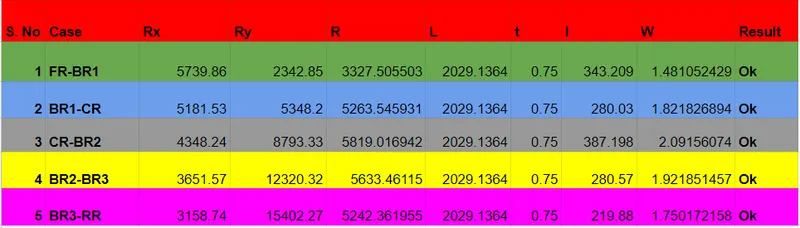
From above table it can be concluded that all the values of W is less than 2.7 and not greater than 3.1. So the current positioning of roof is good as per the design.
Snow Load criteria:
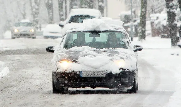
Snow load study is done to check the withstand ability when the snow loads over the roof during winter season in snow fall regions. This study will also analyze that whether permanent deformation occurs after the removal of the snow load. So the roof is designed in such a way that if the snow load on the roof then it may bend but needs to be back in its original position after the removal of snow load.
Snow load Prediction formula;
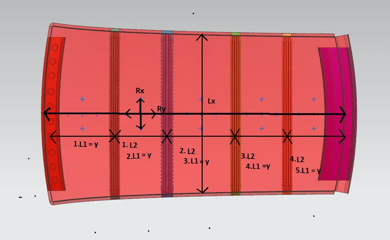
Qr = [Iy x t2] / [a x s x [(Rx + Ry)/2]2 x 10-8]
Where
a = My x Lx2 x 10-12 , My = Y(Ly-Y)
Judgement condition = Qr ≥ 3.1
250 ≤ s ≤ 380
t = Roof plate thickness [mm]
Ly = Distance between the front and rear roof Rails on the Vehicle along with 0Y[mm]
Length of Roof panel with the center point between Roof rail Front /Rear as the front and rear reference point.
Lx = Distance between the Left and Right end of the roof on the Roof BOW [mm]
Width of the roof panel exposed on the surface.
Y = Distance front Front Roof Rail to Roof BOW[mm]
s = Distance for which Roof BOW bears divided load [mm]
s = L1/2 + L2/2
Iy = Geometrical moment of inertia of Roof BOW (Y cross-section )[mm4]
Rx = Lateral direction curvature radius of roof panel Y cross-section on Roof BOW [mm]
Roof panel curvature Radius of the Length Lx in Front view
Ry = Longitudinal Direction curvature radius of the Roof panel X cross-section on Roof BOW
[mm]
Roof panel X curvature radius of length s in Side view
Input data:
Calculation:
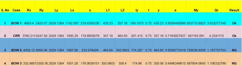
From the above calculations, the first two cases satisfy the condition but the last two cases failed to satisfy the condition. Hence the embosses should be created on the roof surface in order to increase the stiffness of the roof.
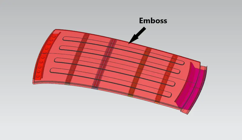
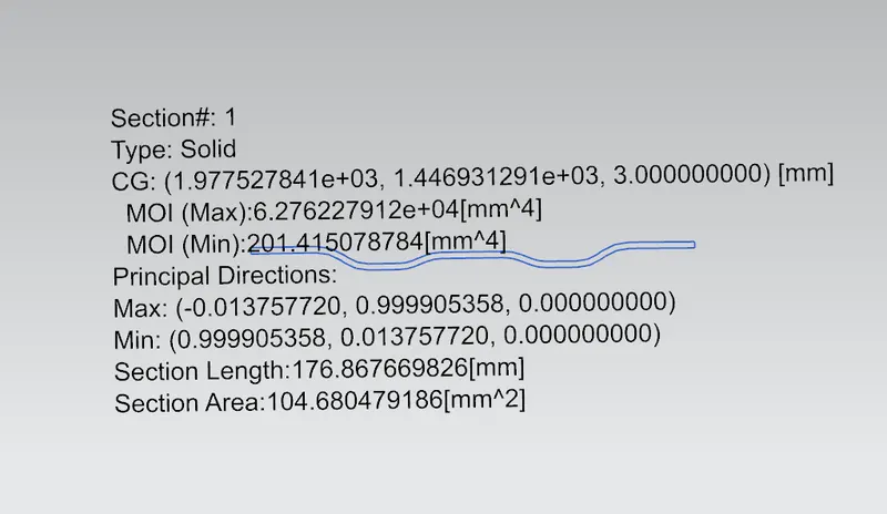
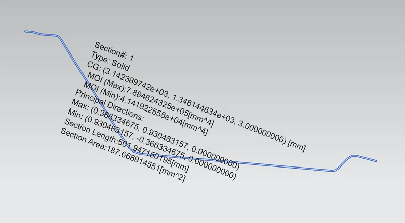
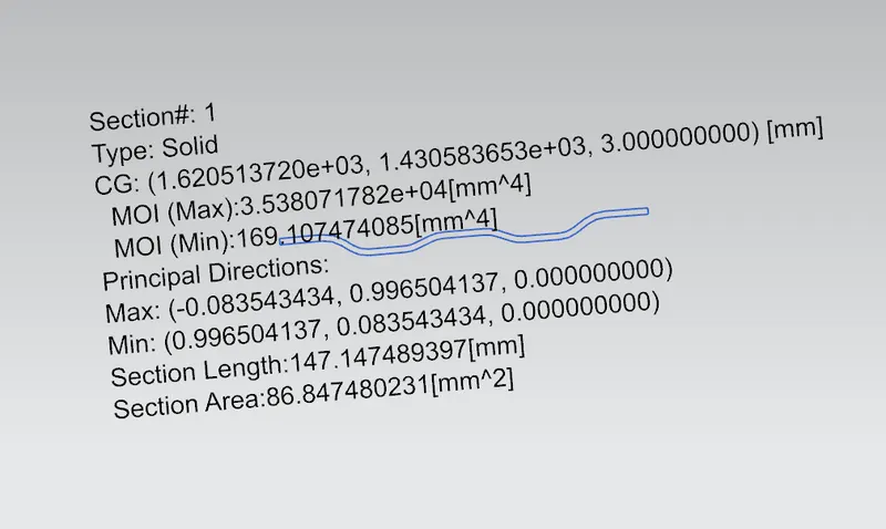
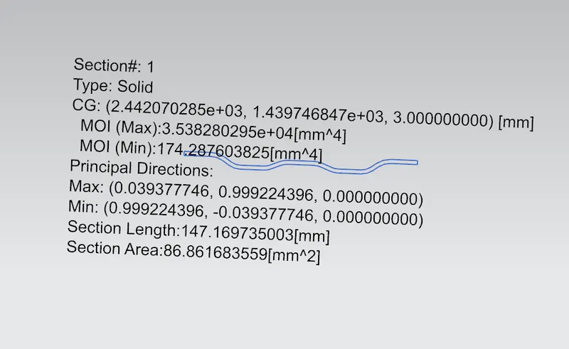
Section Modulus:
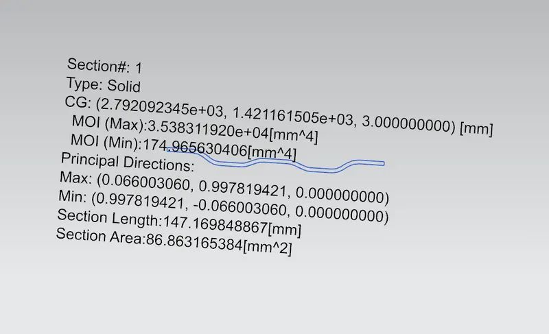
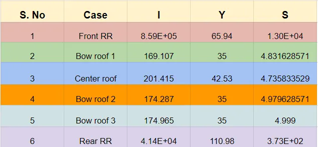
Section modulus is a geometric property for a give cross-section used in the design of beam or flexular members. It is termed as the ration of moment of inertia and the distance from neutral axis to the extreme edge.
It is given by
S = I/Y
Where,
I = Moment of inertia
Y = Distance from neutral axis to the extreme edge
PMI of Front Roof Rail:
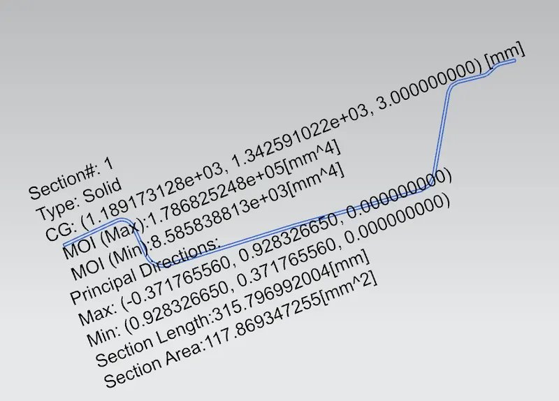
PMI of center roof rail:
PMI of rear roof rail:
PMI of bow roofs:
Bow roof 1
Bow roof 2
Bow roof 3
Calculation:
Draft Analysis:
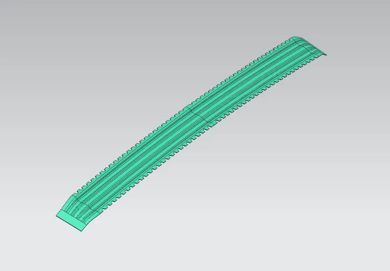
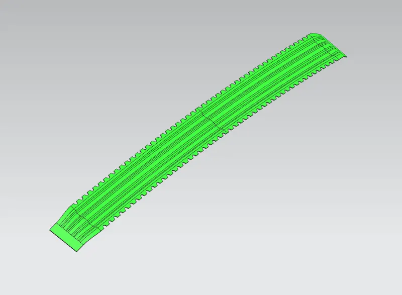
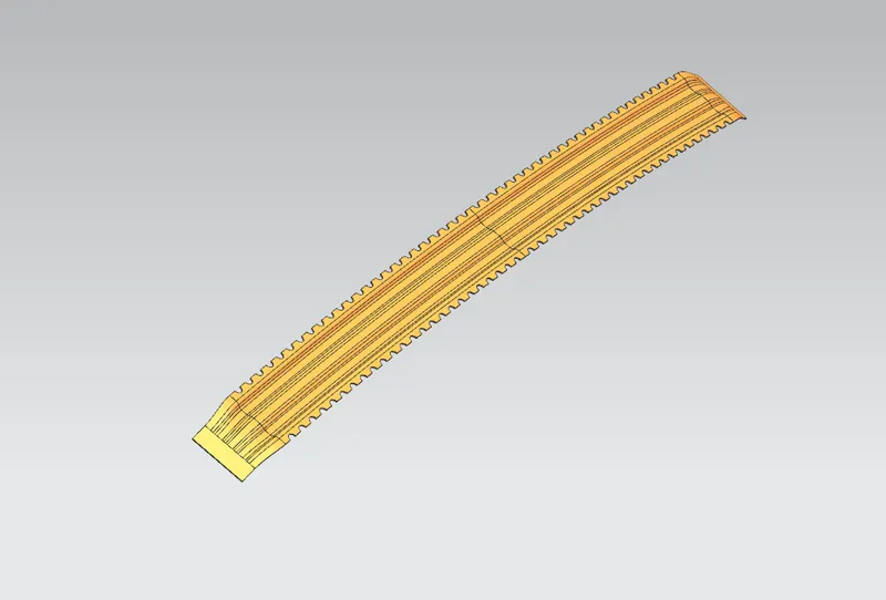
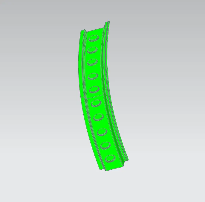
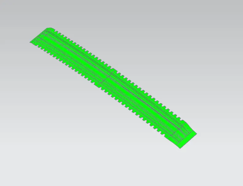
Before sending the design to the manufacturing team draft analysis is done in order to check if the part can be easily removed or not. This type of analysis is done based on the colour ranges identifying zones on analyzed element where the deviation from the draft direction at any point, corresponds to specified values.
The minimum angle of 7˚ is considered for the analysis. Green colour infer on the parts that all face along the tooling direction has posistive draft angle greater than 7˚ and passed in analysis.
Draft analysis of front roof rail:
Draft analysis of center roof rail:
Draft analysis of rear roof rail:
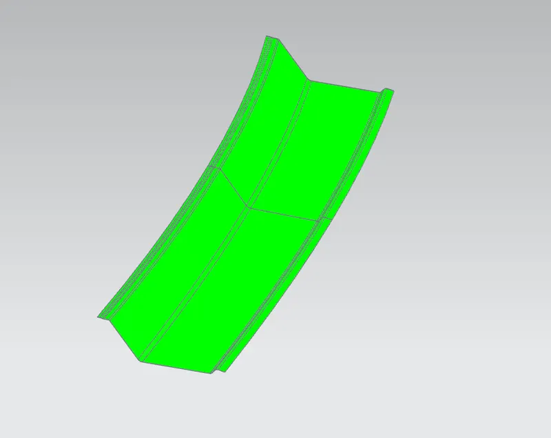
Draft analysis of bow roof 1, 2 and 3:
Bow roof 1
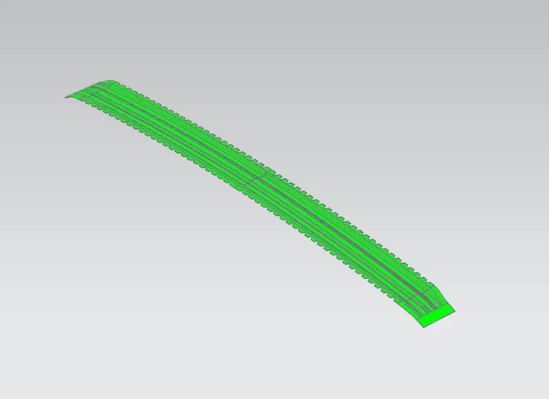
Bow roof 2
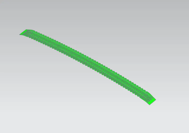
Bow roof 3
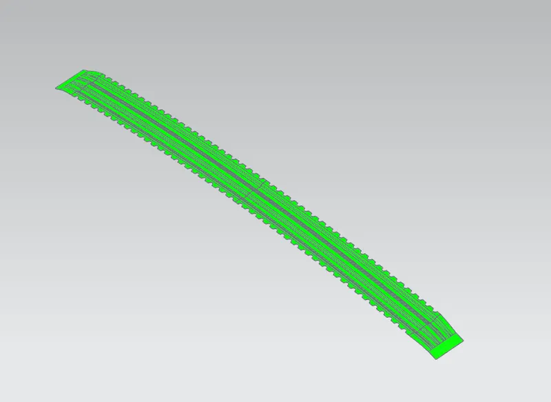
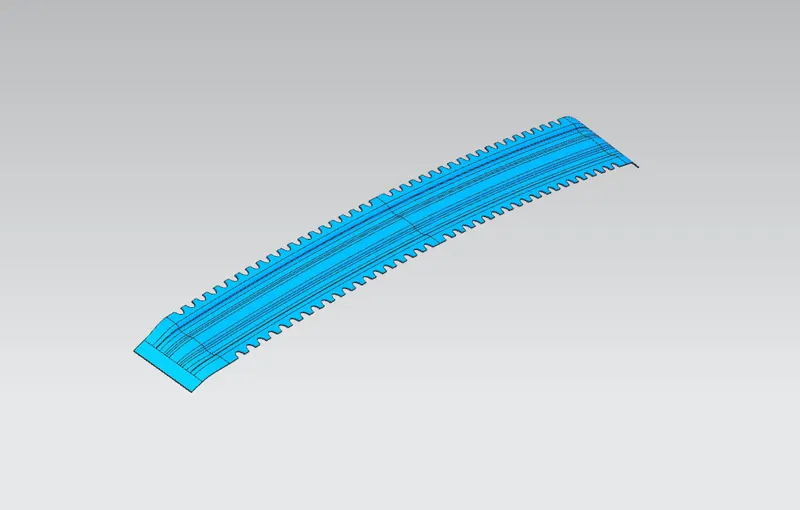
Draft analysis of outer panel:
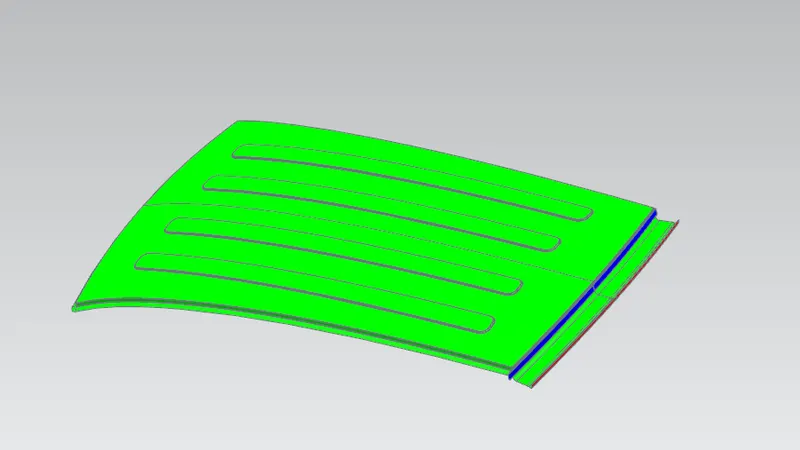
The region showing blue colour is not manufactured by deep drawing operation, it will be done by bending operation.
Manufacturing process used in Roof Design:
Deep Drawing:
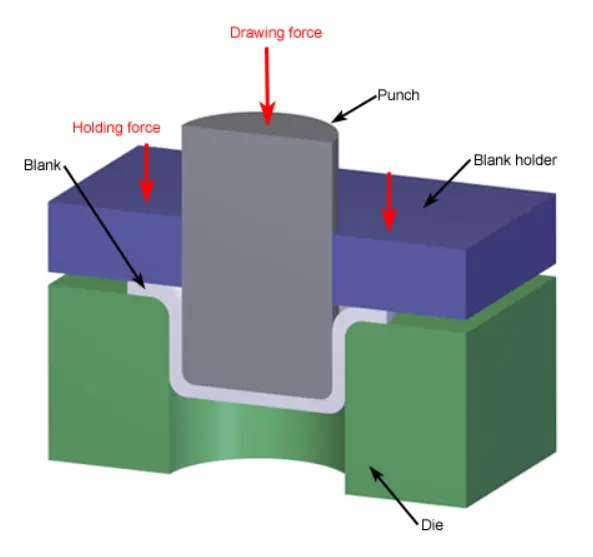
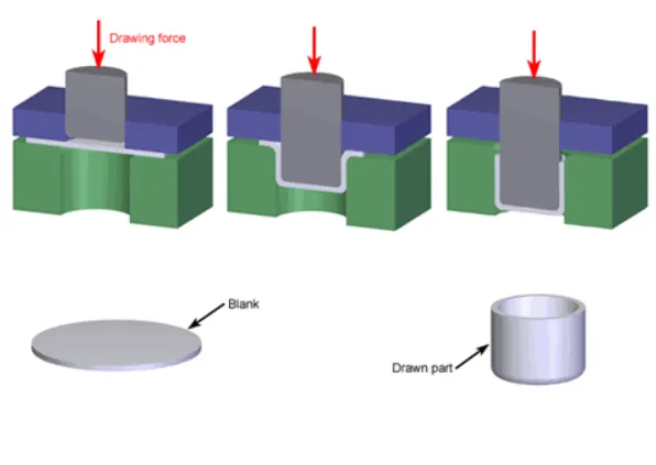
Deep drawing is a metal forming process in which sheet metal is stretched into the desired part shape. A tool pushes downward on the sheet metal, forcing it into a die cavity in the shape of the desired part. The tensile force is applied to the sheet cause it to plastically deform into a cup shaped part. The deep drawn parts can have variety of cross-sections with straight, tapered, or even curved walls, but cylindrical or rectangular parts are most common. This process requires a blank, blank holder, punch and die. Deep drawing is most effective with ductile metals.
Bending:
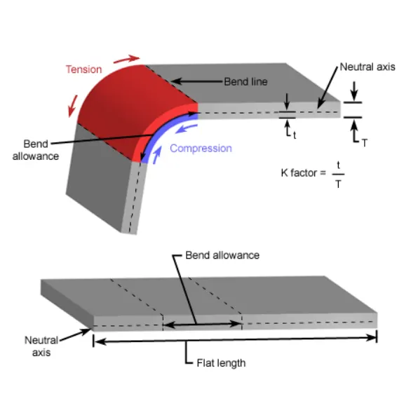
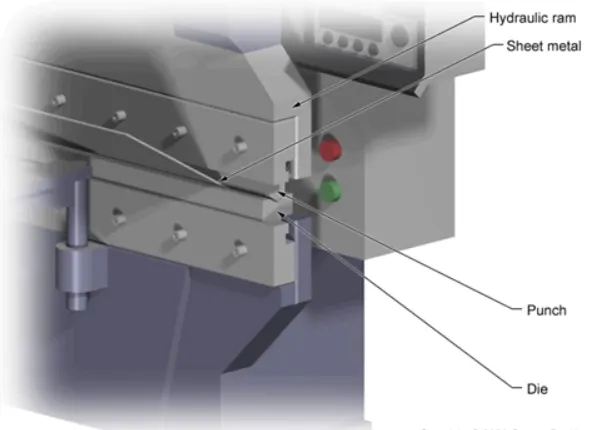
Bending is a metal forming process in which a force is applied to a piece of sheet metal, causing it to bend at an angle and form the desired shape. This operation causes deformation along one axis, but asequence of several different operations can be performed to create a complex part. The act of bending results in both tension and compression in sheet metal. The outside portion of the sheet will undergo tension and stretch to a greater length while the insid eportion experiences compression and shortens. The neutral axis is the boundry line inside the sheet metal, along which no tension and compression forces are present. As a result, the length of this axis remains constant. The changes in the length to the outside and inside surfaces can be related to the original flat length by two parameters; bend allowance and bend deduction. Bending is typically performed on a machine called a press brake, which can be manually or automatically operated.
Conclusion:
Hence, the desig of roof along with its components was done and checked for heat distortion criteria and snow load criteria in which the design was passed in heat distortion but failed at some portion in snow load due to the embosses were provided in order to in crease the stiffness of the roof. At last draft analysis was done for manufacturability and was passed.