Roof challenge
ROOF DESIGN CHALLENGE
INTRODUCTION:
An automobile roof or car top is the portion of an automobile that sits above the passenger compartment, protecting the vehicle occupants from sun, wind, rain, and other external elements.
OBJECTIVE:
In this project we are going to design the bow roof rails, front roof rail, rear roof rail and center roof rail by using NX CAD and we are going to see the purpose of the roof and the reinforcement rails that we are going to design.
FEATURE/TOOL USED:
- Sketch
- Law extension
- Offset surface
- Trim sheet
- Offset curve in face
- Bridge curve
- Trim and extend
- Studio surface
- Through curve mesh
- Face blend
- Edge blend
- Sew
- Mirror geometry
- Intersection curve
- Projected curve
- Thicken
For testing the roof we have to do roof rollover test
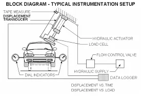
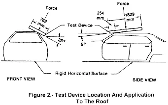
We do this test to know how much the roof can withstand.
DESIGN REQUIREMENTS:
For designing the roof rails and reinforcement rails we have consideration and some parameters to follow.
First we are going to see the front roof rail requirements.
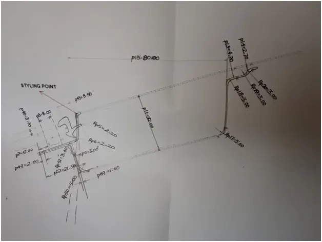
Front roof master sketch
As we are going to follow the master sketch for the front roof rail design and the values in it has a purpose and it’s the minimum value which we can’t go below that as this master sketch will be provided to you by the project team for us we are going to learn this parameters and learn how to follow the industry standards.
The values are been set considering the vision criteria the windshield placement criteria and the headliner criteria.
Now we are going to design front roof rail as per the master section.
And the purpose of the front roof rail is to provide strength to the roof.
And it will be joined to the outer roof by mastic and for that we have to give a space between the roof and the front roof rail of minimum 5mm and mastic point gives additional strength to the roof and also we avoid spot welding to the outer roof as it will distort the aesthetic look of the outer roof.
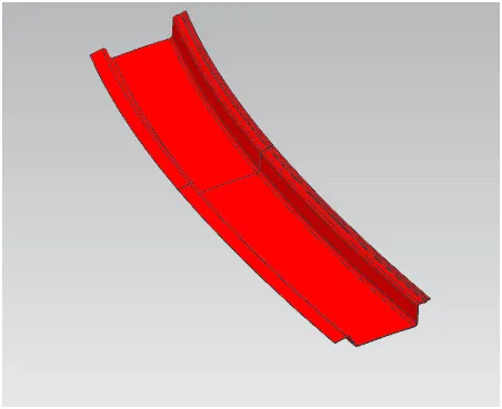
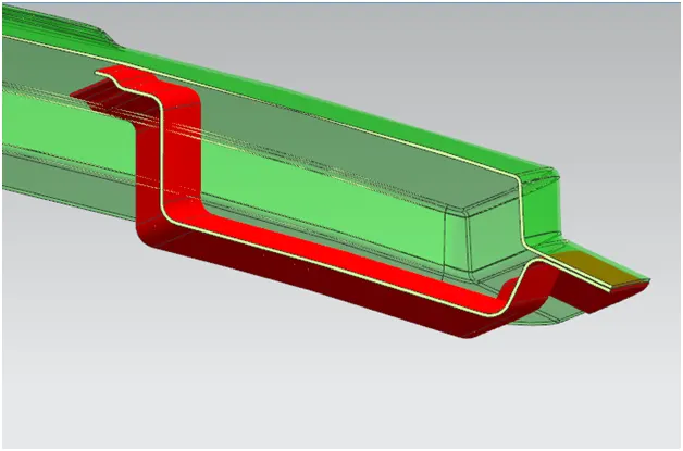
As you can see in the above images we have created the front roof rail in NX CAD and also we have maintain the specific distance between the outer roof and the front roof rail to have mastic clearance.
Now we are going to make the rear roof rail it is similar to the front roof rail and the master section is been provided to us and we will follow that.
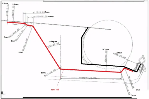
Rear roof rail master section
As you can see there are hinge points at the master section and it is for the back door assembly to the rear part of the roof. so according to this we have created the rear roof rail.
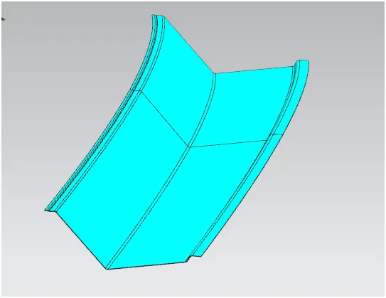
Rear roof rail
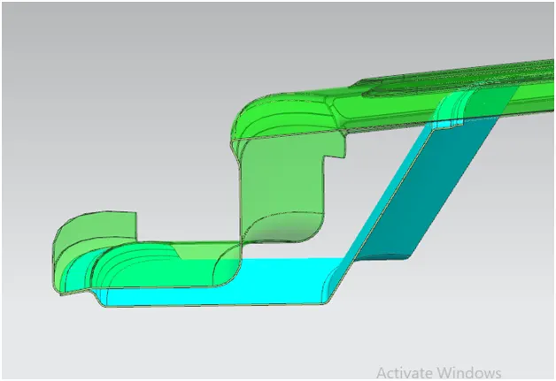
Section view of rear roof and outer roof
As this roof rail is going to provide the strength to the roof.
Now we are going to design the bow rail roof and center reinforcement rail roof.
For bow roofs the purpose is to have a good strength to it and have a nice curvature to the roof for having bow roof and center roof we need to calculate the position of it on the roof and that is because that it has a crucial role which is that to have a more strength to it and to predict the location best where it can perform the best.
So for that we have several consideration but we are going to use to criteria which is
- HEAT DISTORTION
- SNOWED LOAD
We will see now what is this heat distortion and snowed load criteria and how we are going to calculate it.
Bow–roof prediction Formula
W = [1.73 x 10^(-3) x L] + [1.85 x 10^(-8) x (R^2)/t] + [ 1.10x10^(-3) x l] - 2.68
Judgement Condition : OK< 2.7> 3.1
Where
L = Roof Length in X-Direction[mm](Roof dimension in 0-Y)
R = Roof curvature
R = 2(Rx*Ry)/(Rx+Ry)
Rx = X curvature
Ry = Y curvature
t = Roof plate thickness [mm]
l = Bow Roof Span [mm]
Snow load Prediction formula
Qr = [Iy x t2] / [α x s x [(Rx + Ry)/2]2 x 10-8]
Note: The Qr value given over here is correct. There was a typo error in the formula given in the video.
Where
α = My x Lx2 x 10-12 , My = Y(Ly-Y)
Judgement condition = Qr ≥ 3.1
250 ≤ s ≤ 380
t = Roof plate thickness [mm]
Ly = Distance between the front and rear roof Rails on the Vehicle along with 0Y[mm]
Length of Roof panel with the center point between Roof rail Front /Rear as the front and rear reference point.
Lx = Distance between the Left and Right end of the roof on the Roof BOW [mm]
Width of the roof panel exposed on the surface.
Y = Distance front Front Roof Rail to Roof BOW[mm]
s = Distance for which Roof BOW bears divided load [mm]
s = L1/2 + L2/2
Iy = Geometrical moment of inertia of Roof BOW (Y cross-section )[mm4]
Rx = Lateral direction curvature radius of roof panel Y cross-section on Roof BOW [mm]
Roof panel curvature Radius of the Length Lx in Front view
Ry = Longitudinal Direction curvature radius of the Roof panel X cross-section on Roof BOW [mm]
Roof panel X curvature radius of length s in Side view
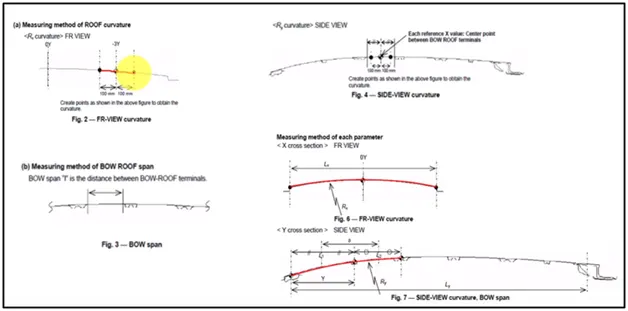
Measuring of roof curvature
So this is the formula and condition which is going to tell how are bow roof design has accomplished it or not.
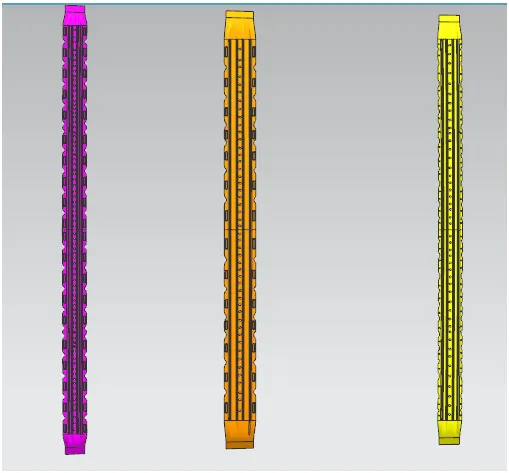
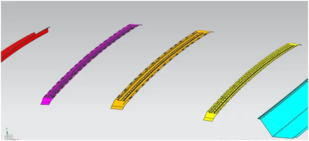
Bow roof and center reinforcement roof
As you can see I have created the bow roofs and also I have created emboss and also made material removal as much as possible so that we don’t have heavy weight sheet metal parts.
Now we will do the calculation of it and draft analysis of the bows.
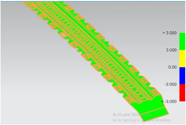
Draft analysis : Draft analysis is a method of checking the draft angle on various faces of a part with a particular direction.
Draft analysis is done to make sure the part you have created can be easily remove when it gets punched or stamped by the pressing tool or machine.
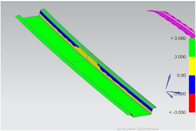
Draft analysis for front roof
Draft analysis for bow roof 1
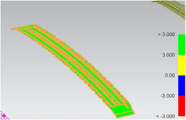
Draft analysis for center bow roof
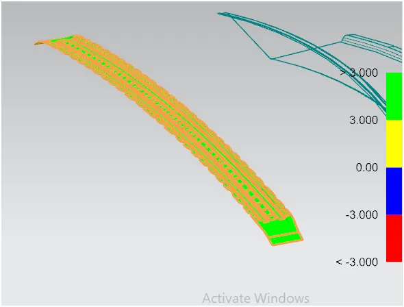
Draft analysis for bow roof 2
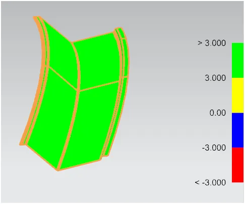
Draft analysis for rear roof
As you can see the images we got a good result.
Now for sheet metal the draft angle should be minimum 3 degree so we tested on that draft angle and as you see the images the images turns to be green which indicates we have a positive draft and where ever you see blue and red color that means at that portion the draft angle is -3 degree and less than -3 degree respectively which is not acceptable if your draft analysis show red color area that means you have negative draft so it is not going to stamp or forming properly.
Yellow and green color is acceptable for further procedure.
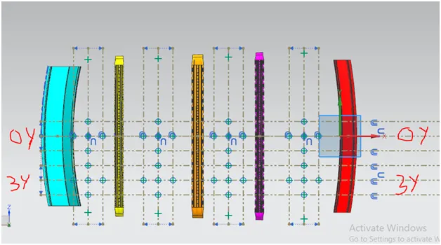
Sketch
So we have done the heat distortion around the 3y axis
And snowed load on 0y axis.
And according to that we have calculated it.
|
SR NO. |
BOWS |
Rx(mm) |
Ry(mm) |
R(mm) |
I(mm) |
L(mm) |
t(mm) |
(R^2)/t (mm) |
W(mm) |
OK/NG |
|
1 |
FR & 1ST |
3993.4211 |
3695.0037 |
3838.421035 |
519.9397 |
2028.006 |
0.75 |
19644634.73 |
1.763809792 |
OK |
|
2 |
1ST & CTR |
7426.5906 |
6980.6295 |
7196.70791 |
351.1699 |
2028.006 |
0.75 |
69056806.32 |
2.492288187 |
OK |
|
3 |
CTR & 2ND |
2457.2173 |
11081.5637 |
4022.490656 |
464.9994 |
2028.006 |
0.75 |
21573908.11 |
1.73906702 |
OK |
|
4 |
2ND & RR |
3250.0966 |
11098.9972 |
5027.887275 |
279.5704 |
2028.006 |
0.75 |
33706200.6 |
1.759542531 |
OK |
Heat distortion result
As we have satisfied the condition for the heat distortion we have created proper bow roof and center roof.
For snowed load we have to calculate moment of inertia of bow roofs
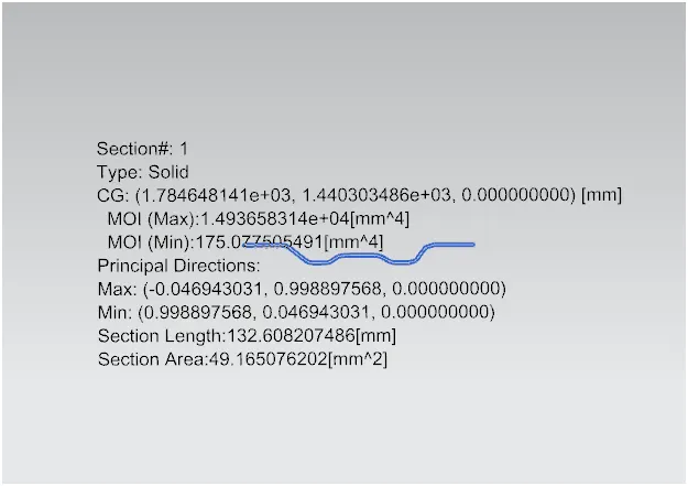
Moment of inertia for bow roof 1
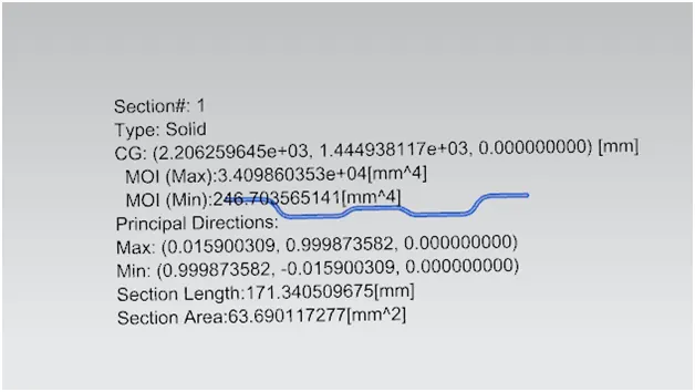
Moment of inertia for center roof
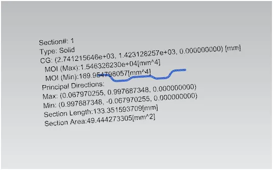
Moment of inertia for bow 2
|
SR NO. |
BOWs |
Iy(mm^4) |
ALPHA |
My |
Lx |
Ly |
Y |
s |
l1 |
l2 |
Rx |
Ry |
t |
Qr |
Determination(Qr) |
|
1 |
FR & 1ST |
175.0775055 |
1.097676491 |
859647.3329 |
1129.9963 |
2028.006 |
603.4488 |
512.537 |
603.448 |
421.626 |
6424.6562 |
3730.2802 |
0.75 |
0.6789829474 |
NG |
|
2 |
1ST & CTR |
246.7035651 |
0.7903567693 |
677291.5739 |
1080.2487 |
2028.006 |
421.626 |
478.3071 |
421.626 |
534.9882 |
2970.7559 |
4561.2778 |
0.75 |
2.588233356 |
NG |
|
3 |
CTR & 2ND |
169.9547981 |
0.8907532662 |
798741.1572 |
1056.0286 |
2028.006 |
534.9822 |
476.3873 |
534.9882 |
417.7864 |
4313.933 |
11704.8065 |
0.75 |
0.3511896204 |
NG |
|
4 |
2ND & RR |
0.7311161355 |
672727.8499 |
1042.4938 |
2028.006 |
417.7864 |
208.8932 |
417.7864 |
0.75 |
#DIV/0! |
Snowed load result
For snowed load the value doesn’t satisfy.
So for now improving the strength to the roof what we can do is to create emboss on the roof outer panel or we can improve the roof curvature by sending it back to the styling team.
For now I have created emboss on the roof outer panel for strength.
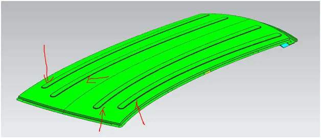
Embossed roof
As this will improve the strength of it
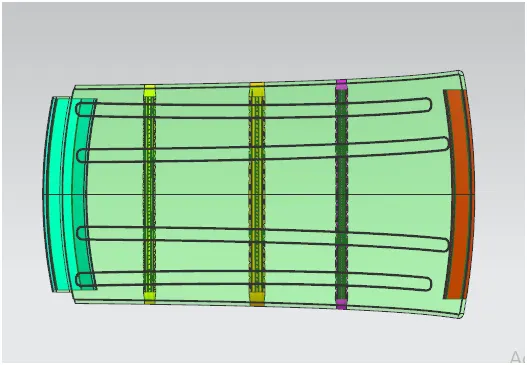
Top view
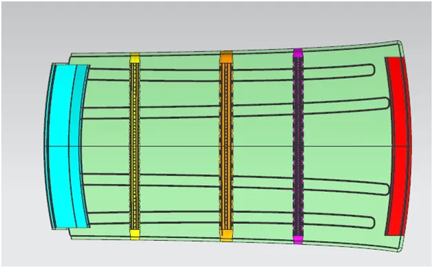
Bottom view
CONCLUSION:
We are successfully able to design the roof reinforcement rails in NX CAD and have studied whether they have satisfied the roof design requirements or not.