Photo Realistic Rendering
RENDERING AND MODELLING OF AMERICAN CHOPPER BY USING SOLIDWORKS
INTRODUCTION: In this project we will try to understand and learn the features which are used to do a part modeling and rendering by using solidworks and solidworks visualize solidworks is a software which helps to design and model three dimensional parts.
OBJECTIVE: Is to understand the features and function of the solidworks and solidworks visualize which is used for modeling and rendering respectively for the American chopper. And to get better insight of the features and tools which are used for modeling of the part and to know how exactly they work and also to get familiar with user interface of the solidworks.
DESIGN METHODOLOGY:
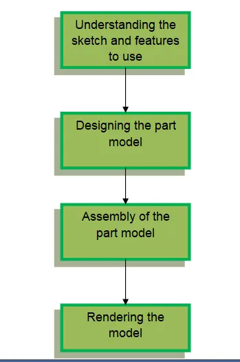
FLOWCHART
Description
We will try to understand the sketch and design according to that as with mentioned dimension .
And we will sketch and constraint the sketch and making it fully defined so that we can convert it to a model.
After that we make all the parts and will be given suitable appearance as per the part requirement for the chopper and then we assemble it.
After the assembly we will render the model to give a realistic look by using solidworks visualize.
And part by part steps will be shown as follows.
PART MODELLING
- Transmission Belt
It is used to transmit the power from the engine to the wheels.
FEATURES/TOOLS USED
- Sketch
- Offset
- Extrude boss
- Fillet
- Appearance
For making of transmission belt we will sketch on the front plane and will sketch according to the requirement after creating the sketch we will offset it and extrude boss it to get the require 3D model and then we will give some fillets to give a round shape edge to the belt and finally add a proper appearance to the belt.
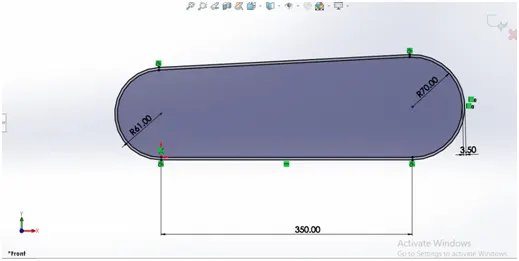
Sketch of Transmission Belt
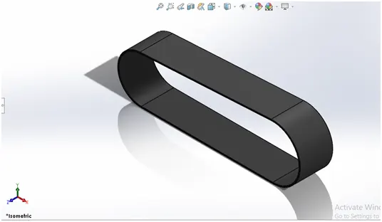
3D model of Transmission Belt
- Front Fender
It prevents to get dust , dirt and small pebbles to not hit the rider and components of the bike when the wheel rotates and it is located at the front of the chopper on the tyre.
FEATURES/TOOLS USED
- Sketch
- Dynamic mirror
- Revolve boss
- Split
- Fillet
For making the front fender we will sketch it and also use of dynamic mirror entity which helps to mirror the sketch we want and we can do that by giving the reference plane of the sketch and it will mirror the sketch on the opposite side of the sketch we drawn with same dimension.
And after that we use revolve boss to make the model and then we use split feature which actually cut out the unnecessary part from the revolve part and get the desire shape we want and after that we give some fillets to it as mentioned and lastly we apply the appearance to the front fender.
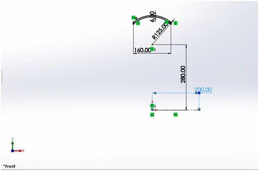
Sketch of front fender
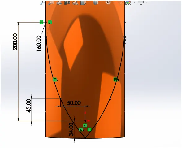
Sketch for the split by using dynamic mirror entity
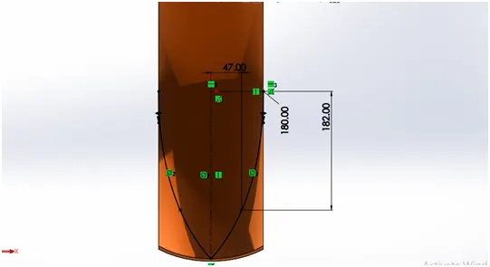
Sketch for the split by using dynamic mirror entity
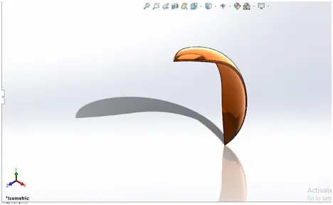
3D model of front fender
- REAR FENDER
It has the same purpose as the front fender just the positioning is on the rear part and it is called as a rear fender.
FEATURES/TOOLS USED
- Sketch
- Dynamic mirror
- Revolve boss
- Split
- Shell
- Decals
As we sketch the front fender it is the same procedure we use for rear fender just there is a change in dimension and we used shell feature to reduce the thickness of the fender from the inside face.
Shell feature is used to give thickness and shallowness to the desire object.
And used decals feature to add graphics to it.
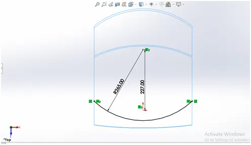
Rear fender sketch
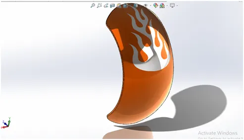
3D model of Rear fender
- CHAIN
It is used to connect the transmission to the rear wheel so that the power can be transfer to the rear wheel
FEATURES/TOOL USED
- Sketch
- Sketch block
- Extrude boss
- Curve pattern
- Fillet
- Mirror entity
For the chain we need to sketch the path for the chain and on that we will add chain links to the path of the chain.
The chain links are made on the same sketch but we will make them as a block ,block is a feature which helps you to make a particular sketch which can be recalled again and again for numerous time we want to use and they will be saved separately as a different sketch for you to use on the sketch whenever you want.
After adding the sketch blocks we will extrude boss them on the path we sketched for it and we will use curve pattern feature which will pattern your chain links on the curve it is a very helpful feature to use so that it decrease the time to sketch new sketch on the curve path again and again to get the desire shape.
So curve pattern saves your time and after making the path with the chain links we will use mirror feature to get the other side of the chain links it basically mirrors the chain links exactly the same but on the opposite side of it.
And lastly we will give some fillets and appearance to the chain.
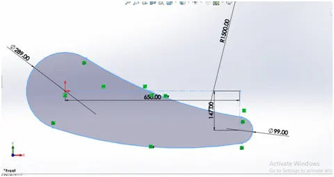
Sketch for chain path
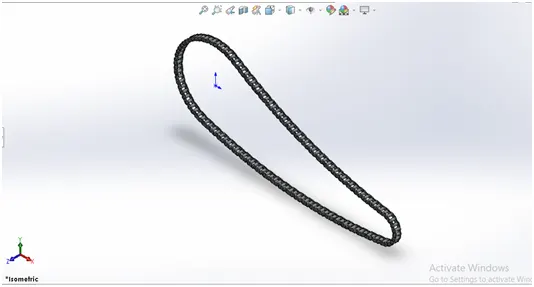
3D model of chain
- KICKSTAND
It is used to support the vehicle to stand on one side
FEATURES/TOOLS USED
- Sketch
- Boss extrude
- Cut extrude
- Loft
- Split
- Dome
- Fillet
For the kickstand we make two elliptical shape sketch as our foundation for the kickstand and we will make another sketch which is passing through this two elliptic sketch and then we will use loft feature.
Loft feature is used to add materials between two or more profiles to create a solid feature.
Then we will cut some part from the lofted surface by using cut extrude feature to make a mount for the kickstand and then by extrude boss we will create a pin to kickstand which can be mounted.
And we will use dome feature to give a nice circular shape to the both end of the lofted solid and we will add desire fillets and appearance to it.
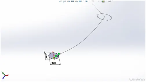
Sketch for the kickstand

3D model of kickstand
- PEDAL STAND
It is used to rest the foot of the driver and also to mount the brakes and gear shifter with it.
FEATURES/TOOLS USED
- Sketch
- Extrude boss
- Linear pattern
- Chamfer
- Dome
- Fillet
For the making of pedal stand we will sketch the pedal in the front plane and then we will extrude it and will add linear pattern feature which is again to make patterns on it.
Then we will provide required dome and fillet to it chamfer feature is used so that we can get pointed cone shape as shown in the model below it is same as fillet just it doesn’t give a radial curve finish like fillet does.
And after making the model at the assembly we will mirror the pedal as it will be on both sides of the chopper.
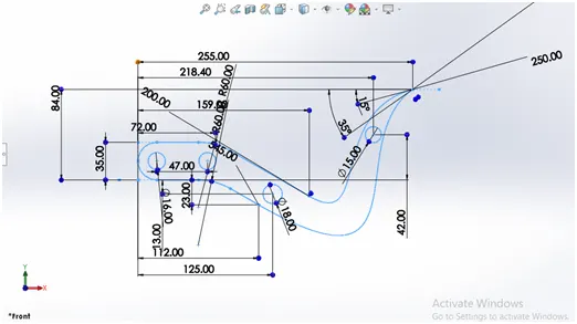
Sketch of pedal stand
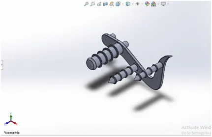
3D model of pedal stand
- FRONT FORK
It is to hold the wheels of the vehicle and which is used to help them steer.
FEATURES/TOOLS USED
- Sketch
- Extrude boss
- Revolve boss
- Sweep
- Combine
- Fillet
- Project curve
- Cut extrude
- Body move
- Combine
For the making of front fork we will sketch the part use extrude boss, revolve and cut extrude features to it and as we explained this feature already in the project before now we get to learn how to use projected curves and compositions curves.
Projected curves are used to project the intersection of two or more curves which has been sketched on different planes as we used projected curves to make the handles, brake wires it gives the proper curve and also you can handle the curve shape according to you not like the 3d sketch.
And we made the brake wire and handle bar by projected curve and extrude boss.
We used body move feature to the headlight bucket as we wanted it to move offset from the fork rod so that it looks proper headlight bucket.
We also used sweep at the handle bar of the fork sweep feature is used to make a closed profile along an open or closed path to create a solid body.
We also learned how to add new view which is in the view orientation tab to the fork so that we can get best view of the fork.
We did used the combine feature so that we can make the different parts as a one body.
And we did the fillets and appearance which is required.
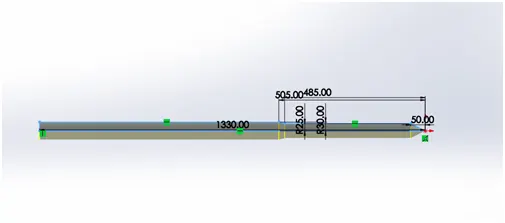
Sketch of fork
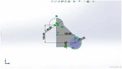
Sketch of fork clamp
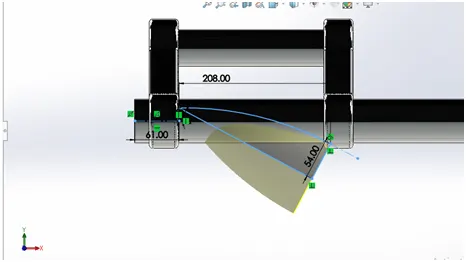
Sketch of headlight bucket
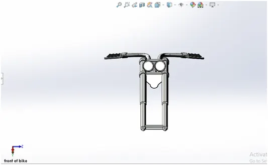
3D model of front fork
- OIL TANK
Oil tank is used to store the oil of the vehicle.
FEATURES/TOOLS USED
- Sketch
- Boss extrude
- Combine
- Fillet
- Shell
- Decals
As we sketch the oil tank on as mentioned we then used boss extrude and the made the model.
Then we used combine feature to take the common part of the body that we wanted to be there and selected the sketch accordingly to that.
And in the end we applied fillet and shell feature, by using shell feature we were able to make the tank shallow.
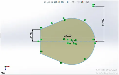
Sketch of oil tank on top plane
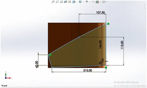
Sketch of oil tank on front plane
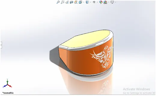
3D model of oil tank
- GAS TANK
It is used to store fuel of the vehicle.
FEATURED/TOOLS USED
- Sketch
- Sketch picture
- Surface sweep
- Projected curve
- Surface trim
- Surface loft
- Boundary surface
- Knit surface
- Cut sweep
- Split line
- Fillet
- Shell
- Decals
As we before start to sketch we needed some reference to draw the sketch for the gas tank so we used sketch picture inn that feature you are able to use a image which can be imported to the planes you wanted then we can start sketching on the image by making it transparent and with the proper scaling of it.
And we used surface sweep feature to sweep a surface along the path that we have given to it instead of solid body it creates solid surface which will be showed below the image.
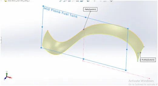
Surface sweep
After making of the surface we used surface trim feature to trim out the excess part of it.
And we used projected curves to give a path for the further surface loft, boundary.
Surface loft is just like loft feature only the difference is that it creates surface.
Surfa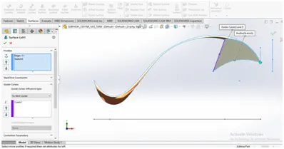 ce loft
Boundary surface makes surface between profiles in two direction.
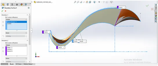
Boundary surface
Knit surface features surface is used to combine two or more adjacent non intersecting surfaces together and make them one.
And after making the gas tank we made the seat by extruding it on the surface of the gas tank using split line feature which is used to project the sketch to the selected surface.
And we did give the shell features to it so that we get a hollow gas tank and made a sweep cut to the front of the gas tank so that it can seat properly on the chassis.
And we gave the necessary fillets and decals to it and finally giving the appearance to the model.
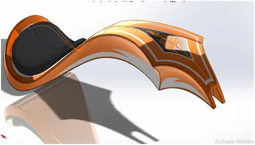
3D model of gas tank
- Engine
Engine is used to generate power from the fuel and transfer it to the transmission.
FEATURES/TOOLS USED
- Sketch
- Sketch picture
- Boss extrude
- Revolve boss
- Circular pattern
- Linear pattern
- Cut extrude
- Dome
- Chamfer
- Split
- Sweep
- Composite curve
- Fillet
As we start to sketch the engine we needed reference for the exhaust and the for the v shape engines.
We used the features we know to build the gear box transmission pulley rotors and the fins we created them by using the linear pattern and we made the mounts of the engine so that we can mount that on the chassis.
We created the spark plug wires, exhaust and intakes by using sweep we try to make every part which was possible to make.
We gave the necessary chamfer and fillet to it.
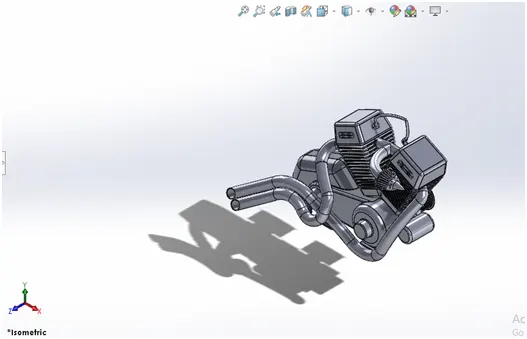
3D model of the engine
- CHASSIS
Chassis is the frame which holds all the components of the vehicle and in the chopper we used is a hard tail chassis.
FEATURES/TOOLS USED
- Sketch
- Sketch feature
- Sweep
- Projected curve
- Boss extrude
- Cut extrude
- Dome
- Split
- Combine
- Mirror
- Chamfer
- Fillet
In chassis we try to use the sketch picture as a reference to make our chassis frame we used the feature we know and made the front tubes of it and at the rear we extrude cut the plate and made a space for the transmission to connect with the rear wheels.
And we made the base for the engine where it going to rest it and made the tabs for the pedal stand and for kickstand so that we can mount those to the chassis and made the circular front tube so that we can mount the frok to the chassis.
And we gave the required fillet, chamfer and appearance to it.
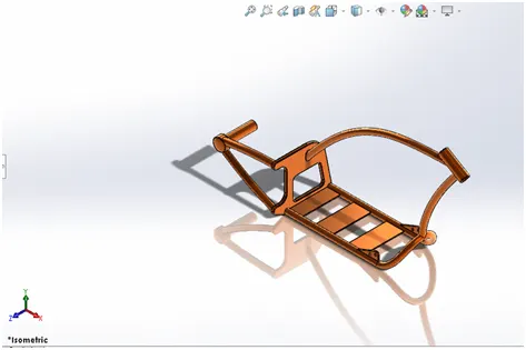
3D model of chassis
- FRONT WHEEL
Wheel is used to revolve on the axle so that the vehicle can move from one place to other and front wheel also used to steer the vehicle.
FEATURES/TOOL USED
- Sketch
- Revolve boss
- Circular pattern
- Extrude cut
- Boss extrude
- Fillet
- Chamfer
- Combine
We used sketch and made the inside rim first with using revolve boss.
And then we made the spider webs and we used circular pattern for making the pattern of spider web then we combined it and made it as a one part.
Then we made the disc of the brake and made the brake caliper to.
Then we have given the fillet, chamfer which is required and then we made the tyre using revolve boss and we made the tyre treads by using extrude cut and then circular patterned it and lastly we have given the appearance to it.
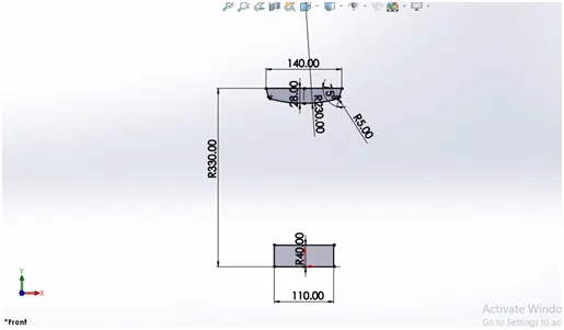
Sketch of front rim
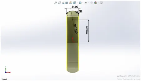
Sketch of front tyre
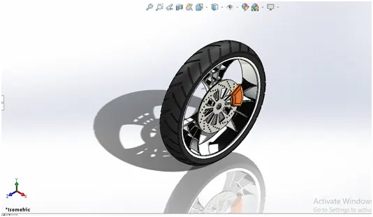
3D model of front tyre
- REAR WHEEL
It has the same function as the front wheel only thing that we are unable to steer the vehicle also the rear has the power transmitted to it and then only the vehicles starts to move in a direction.
FEATURES/TOOLS USED
- Sketch
- Revolve boss
- Circular pattern
- Extrude cut
- Boss extrude
- Fillet
- Chamfer
- Combine
We sketched the rear wheel same as the front wheel just the difference is about the dimension and we add the sprocket to it which is made by extrude boss and made the slots in it by extrude cut and made the circular pattern of the slot.
Then we added the fillet and chamfer and gave it proper appearance to it.
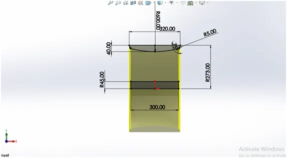
Sketch of rear rim
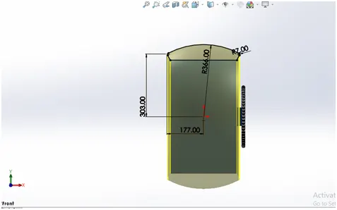
Sketch of rear tyre
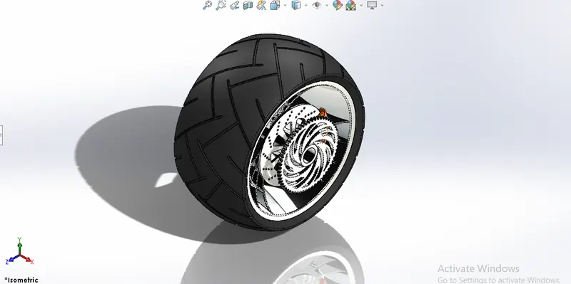
3D model of rear wheel
- ASSEMBLY OF THE CHOPPER
In this we inserted every part of the chopper and then we made the chassis fix so that it doesn’t move.
After we started to insert more components to it and we were mating components plane to the chassis plane so that when move the chassis the entire chopper parts should move together with respect to the chassis.
Then we made few changes so that when we start to render it we should be able to see a real chopper with real characteristics to it.
So we set the kickstand tangent to the assembly top plane so that it can get the tilt look to it.
And we also give the handle a tilted look by adjusting the plane of the of the front fork front plane with an angle limit to the chassis mid plane so that it can tilt the handle to some angle.
We also added camera view to the assembly so that we have a fixed look that we wanted to see when we start the render so it can get more realistic view.
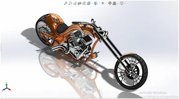
Isometric view
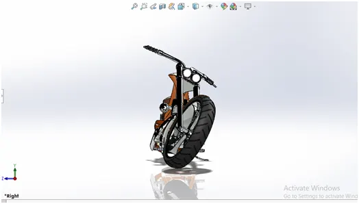
Right view
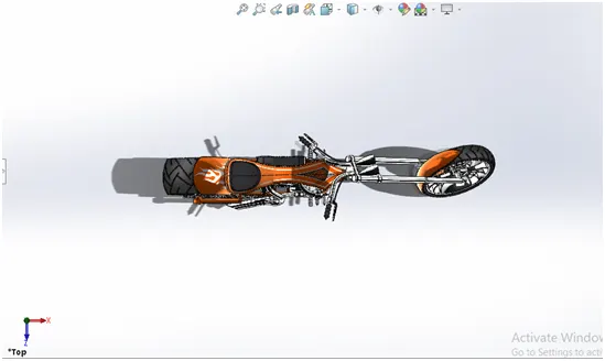
Top view
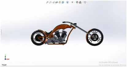
Front view
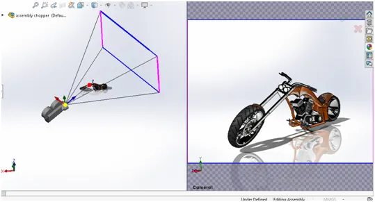
Camera setup view
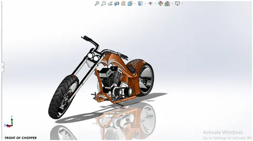
Camera view of assembly
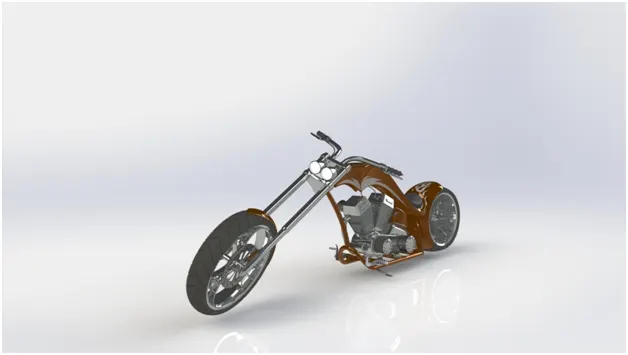
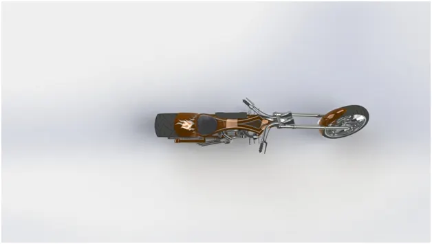
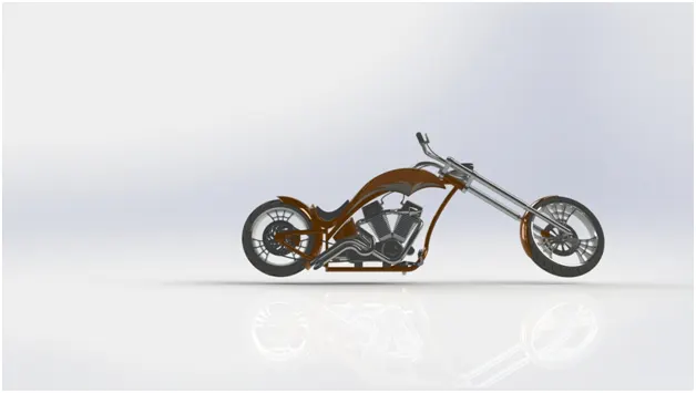
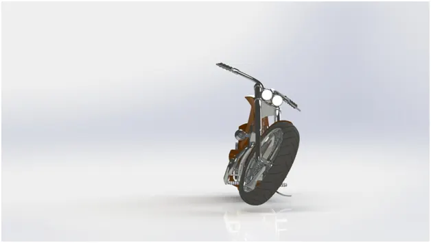
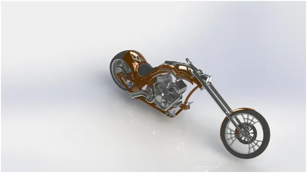
RENDERED IMAGES
- RENDERING
Rendering of the model we did that with the use of soliworks visualize
In order to make our model more realistic and presentable we used rendering.
And we added the different camera views and lighting to it and added the decals to add more graphics to the chopper.
And created a good quality image and added the environment to it so that it looks realistic and more appealing.
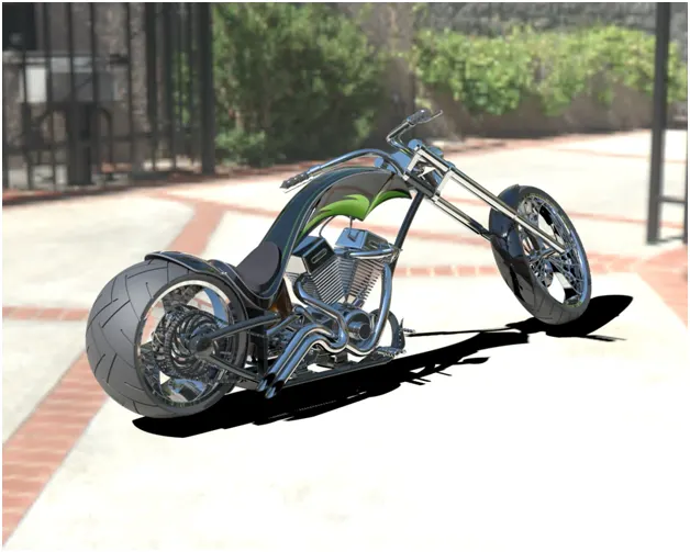
Final rendered image
CONCLUSION
As we were able to create the American chopper and we get to learn the solidworks user interface.
And we are able to learn the basic and important features which are used in solidworks.
And we learn and did a rendering on the model and able to get good result.