Roof challenge
DESIGN OF CAR ROOF
Objective
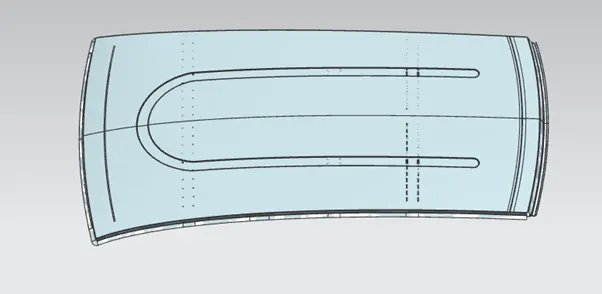
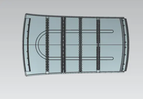
Design an automotive roof based on given styling surface and to create front roof rail ,bow roofs, center roof rail and rear roof rail and to check manufacturability and feasibility of design.
ROOF
An automobile roof or car top is the portion of an automobile that sits above the passenger compartment, protecting the vehicle occupants from sun, wind, rain, and other external elements.
Design consideration
Visibility criteria
Head clearance
Curvature study
Heat distortion and snow load criteria
Material thickness
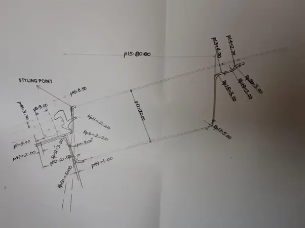
Front Roof Rail
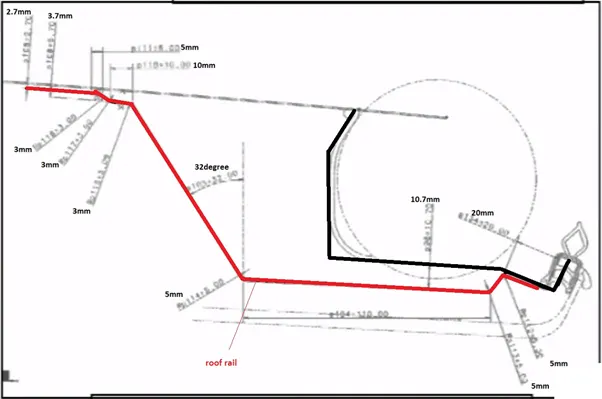
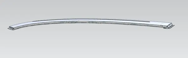
It is used in assembly of roof and provide mounting provision to windshield glass. The measure design consideration here is head room clearance and frontal visibility.
Master section
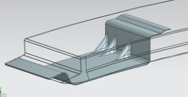
Bow Roofs
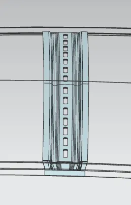
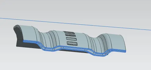
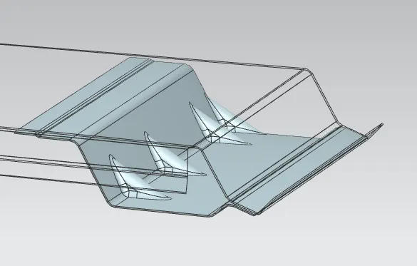
it is an additional stiffening member used in assembly to give strength to the roof and join with the roof by mastic sealant.
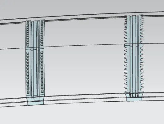
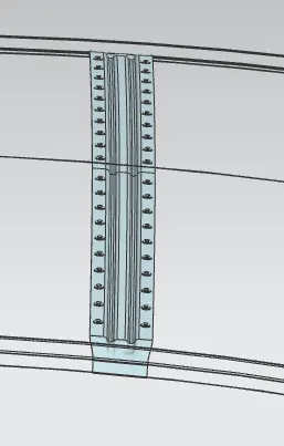
Center roof rail (reinforcement center)
It is used as a cross member between left and tight body side of roof also used to give strength to the roof.
Rear Roof Rail
It is used for back door mounting and the measure design consideration here is rear room clearance and rear visibility.
Master section
Moment of Inertia
Moment of inertia is defined as the quantity expressed by the body resisting angular acceleration which is the sum of the product of the mass of every particle with its square of a distance from the axis of rotation.
M.O.I of Bow Roof 1
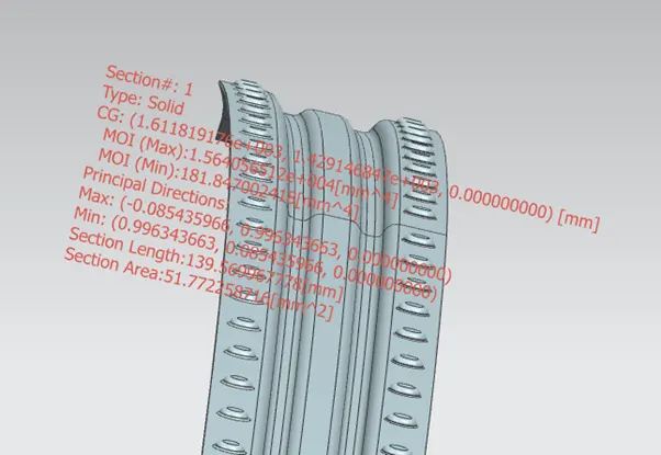
CENTER ROOF
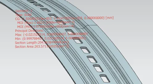
BOW ROOF2
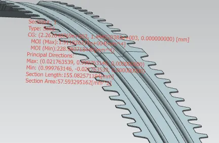
BOW ROOF3
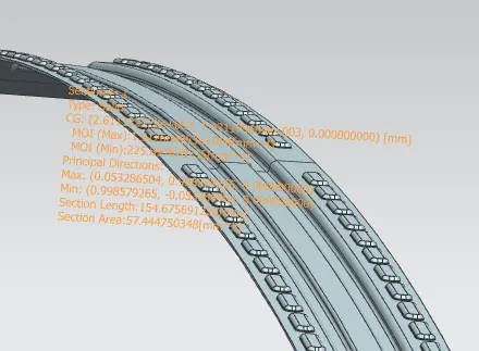
Heat distortion Critera
This is an important consideration while designing sheet metal component. It is a temperature limit above which the material can not use for structural application.
It is used to predict the heat distortion temperature where the material start to soften when exposed to a fixed load at elevated temperature .
In order to avoid damages on roof, based on heat distortion study will predict the bow roof position.
FORMULA
W = [1.73 x 10^(-3) x L] + [1.85 x 10^(-8) x (R^2)/t] + [ 1.10x10^(-3) x l] - 2.68
Judgement Condition : OK< 2.7> 3.1
Where
L = Roof Length in X-Direction[mm](Roof dimension in 0-Y)
R = Roof curvature
R = 2(Rx*Ry)/(Rx+Ry)
Rx = X curvature
Ry = Y curvature
t = Roof plate thickness [mm]
l = Bow Roof Span [mm]
|
SL. NO. |
Position (MM) |
Rx (mm) |
RY (MM) |
R (MM) |
L (MM) |
T (MM) |
l (MM) |
W (MM) |
OK/NG |
|
1 |
FRR&BR1 |
5802.9 |
2434.5 |
3430 |
2029.4 |
0.75 |
341.40 |
1.5 |
OK |
|
2 |
BR1&BR2 |
5263.13 |
5042.05 |
5150.2 |
2029.4 |
0.75 |
236 |
1.08 |
OK |
|
3 |
BR2&CR |
4563.8 |
7888.4 |
5782.28 |
2029.4 |
0.75 |
254.76 |
1.93 |
OK |
|
4 |
CR&BR3 |
3955.368 |
10793.8 |
5789.26 |
2029.4 |
0.75 |
283.83 |
1.96 |
OK |
|
5 |
BR3&RRR |
3325.87 |
14539.23 |
5413.41 |
2029.4 |
0.75 |
443.87 |
2.37 |
OK |
snow load criteria
Qr = [Iy x t2] / [α x s x [(Rx + Ry)/2]2 x 10-8]
Note: The Qr value given over here is correct. There was a typo error in the formula given in the video.
Where
α = My x Lx2 x 10-12 , My = Y(Ly-Y)
Judgement condition = Qr ≥ 3.1
250 ≤ s ≤ 380
t = Roof plate thickness [mm]
Ly = Distance between the front and rear roof Rails on the Vehicle along with 0Y[mm]
Length of Roof panel with the center point between Roof rail Front /Rear as the front and rear reference point.
Lx = Distance between the Left and Right end of the roof on the Roof BOW [mm]
Width of the roof panel exposed on the surface.
Y = Distance front Front Roof Rail to Roof BOW[mm]
s = Distance for which Roof BOW bears divided load [mm]
s = L1/2 + L2/2
Iy = Geometrical moment of inertia of Roof BOW (Y cross-section )[mm4]
Rx = Lateral direction curvature radius of roof panel Y cross-section on Roof BOW [mm]
Roof panel curvature Radius of the Length Lx in Front view
Ry = Longitudinal Direction curvature radius of the Roof panel X cross-section on Roof BOW [mm]
Roof panel X curvature radius of length s in Side view
|
SL. NO |
BOWS |
IY |
α |
LX |
LY |
Y |
S |
RX |
RY |
t |
Qr |
Ok/ NG |
|
1 |
FR&1ST |
181.8 |
.89 |
1140.6 |
2029.4 |
427 |
371 |
2733 |
2494 |
.75 |
4.5 |
OK |
|
2 |
1ST&2ND |
1.07 |
.65 |
1098.5 |
2029.4 |
315.4 |
325 |
2945 |
4934 |
.75 |
0.1 |
NG |
|
3 |
2ND&CR |
229 |
.65 |
1073.6 |
2029.4 |
335.8 |
343 |
3030 |
4954 |
.75 |
3.7 |
OK |
|
4 |
CR&3RD |
225.9 |
.65 |
1057.5 |
2029.4 |
349.8 |
444 |
4293 |
6074 |
.75 |
1.6 |
NG |
Here the 2nd bow roof and tne 3rd bow roof position is not satisfying the condition so we add embosses to add strength to roof.
IMAGES
CONCLUSION
We designed the outer roof , front roof rail, bow roofs, center roof rail and rear roof rail by following the master section all design consideration and parameter .