Photo Realistic Rendering
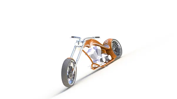
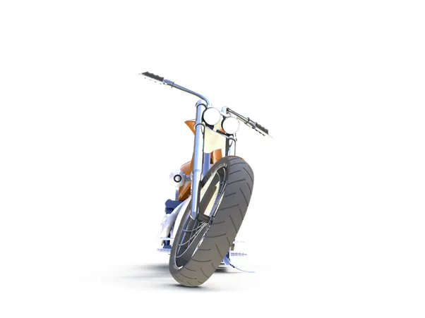
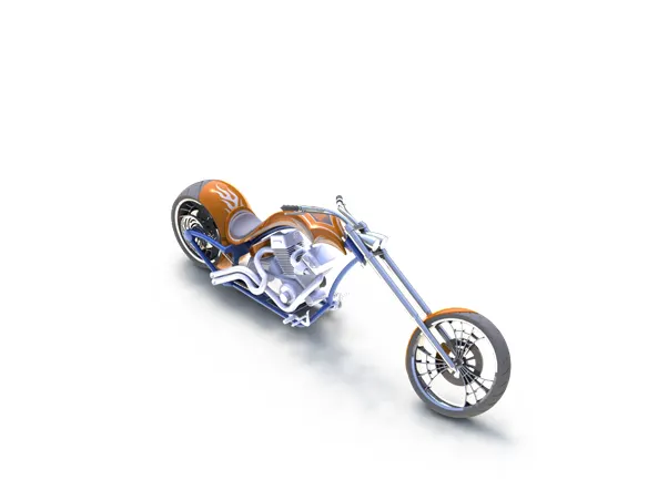
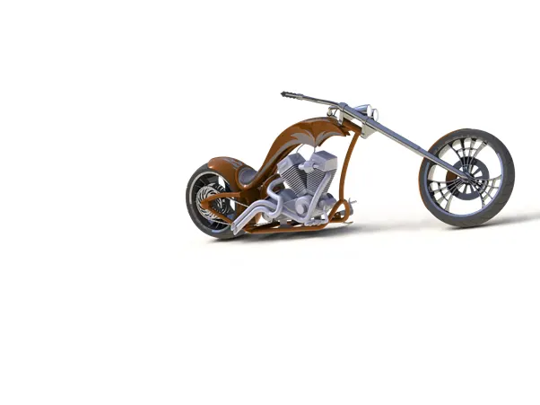
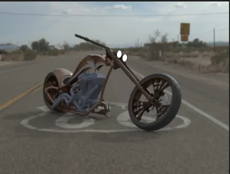
American Chopper Model
INTRODUCTION
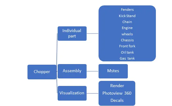
The design process of an American chopper is a high level approach. Here for designing the model we use “ The SOLIDWORK ‘’ CAD software. This software uses a 3D design approach.
This project discusses about concepts and terminology used throughout the SOILDWORKS application. Here are going to study every part of chopper and how we model all and at last we are going to assemble them and the last but not the least we are going to give the model a proper visualization by application of some tools in solidwork.
OBJECTIVE
The primary objective is how we are going to model all the part by specific tools by Solidwork software . How we are going to assemble them to give a proper view, and then we give the model a proper natural effect by using some tools .
DESIGN METHODOLGY
Transmission belt
It used as a source of motion to transmit power efficiently. It transmit power from driving pully to driven pully by friction only.
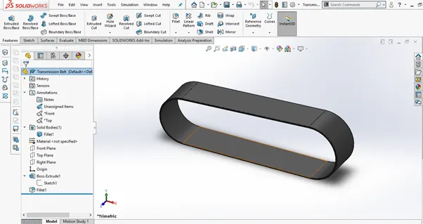
Features used to Create
- Sketch
- Offset
- Extrude
- Fillet
- Appearance
Sketch
It is the basis of a 3D model. You can create on any plane.
Offset
It gives a specified distance to one or more sketch.
Extrude
Here we can extrude the boundary edges of a face of a solid body in a customized direction.
Fillet
It creates a rounded internal or external face on the part.
Appearance
Here we give the object a proper effect to visualize.
Procedure to Model
- First open new part in Solidwork.
- Select the front plane and start sketching and make it a fully defined 2D sketch by giving dimensions and relations.
- Now choose the offset command by selecting the sketch to make a duplicate sketch parallel to the original at a given distance.
- Now exit the sketch and extrude it into 3D model.
- Then apply the fillet and give it a appropriate colour.
Kickstand
It allows the chopper to be kept upright without leaning against another object.
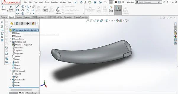
Features used to Create
- Sketch
- Loft
- Dome
- Extrude Boss
- Extrude Cut
- Split
- Fillet
Sketch
Here by choosing new part in solidwork and selecting entities like “line, arc, rectangle, spline, circle etc. we create a 2D sketch.
Loft
It allows you to generate complex geometry in a single feature by adding materials between two or more profiles.
Dome
It creates a cylindrical or conical face by calculating the distance using the radius of the arc.
Extrude Boss/Base
It creates a solid feature by selected sketch counters in one or two directions and give a look of 3D model.
Extrude Cut
It cuts a solid model by extruding a sketched profile in one or two direction.it usually used to create holes, slots etc.
Split
By using this feature you can create separate part files from the new part. To split a surface the trimming surface must extended past the boundaries of the surface to split.
Procedure to Model
- Open a new part in your solidwork and name the Right plane as Mid plane.
- Now select the Mid plane and by using spline and trim entities create a 2D sketch and fully defined it by giving it proper dimensions and relations.
- Then create a new plane normal to the spline and sketch an ellipse on that plane and fully defined it.
- Now by selecting that sketch with spline use the “loft” command to give it a 3D solid model.
- Now by using extrude cut we remove the unnecessary material which is not required for kick stand.
- Then create a boss by sketching a circle and extrude it for attaching it to the fame and apply dome to give the cut a round and smooth surface.
- Then apply fillets to sharp edges and its done.
Front fender
It is also known as mudguards. As the name suggest it protect you and your bike from water, mud and other particles that sprays up into your face.
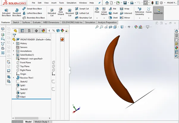
Features used to Create
- Sketch
- Trim
- Offset
- Revolve
- Dynamic Mirror
- Split
- Appearance
Trim
This feature uses to delete a sketch entities.
Revolve
It creates a solid feature around an axis of selected sketch.
Dynamic Mirror
It mirrors faces and bodies about a face or a plane.
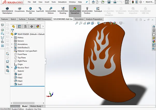
Rear fender
It has the same function as Rear fender also same features to creat.
Chain
It used to transmit power i.e speed and torque through the use of linked chain and sprockets from engine to rear wheel.
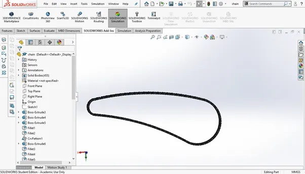
Features used to Create
- Sketch
- Trim
- Extrude
- Block
- Fillets
- Patterns
- Appearance
- Mirror
Block
When making a drawing , you can make blocks to insert into that drawing or you can use it latter. It may be comprised of any single entity or more sketch entities. Relations can then be made between these blocks.
Procedure to make Blocks
- Create a sketch then go to toolbar select Block option then make.
- Select the sketch entities you want to make block
- Now in edit mode add relations and dimensions and make it fully define
- Save the part.
Patterns
This features creates am exact copy of the faces and edges of the original features. Here in chain we use curve driven pattern.
Oil Tank
It is used to store the oil required to run the engine.
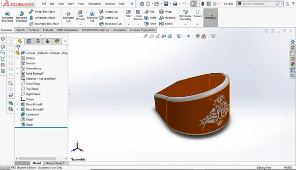
Features used to Create
- Sketch
- Boss extrude
- Combine
- Fillet
- Shell
Combine
It used to combine two or more solid bodies.
Shell
It removes material from a solid body to create a thin walled feature.
Pedal
It attached to the chassis of chopper and the rider used to place his leg on that.
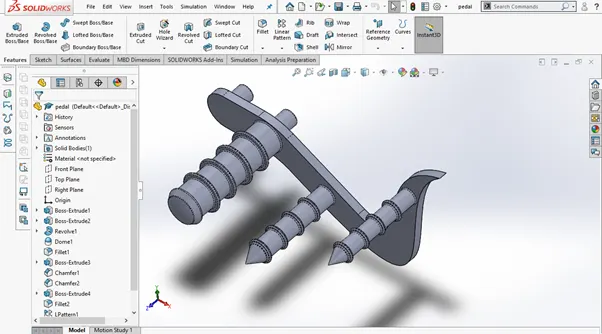
Features used to Create
- Sketch
- Extrude
- Revolve
- Chamfer
- Dome
- Linear Pattern
- Fillet
Chamfer
It creates a beveled feature or gives an angle on selected edges or faces. In property manager we can set the distance an angle.
Linear Pattern
It patterns selected faces or bodies in linear direction.
wheel
It makes the vehicle move by transmitting force i.e transforming torque into tractive force from the tires to road.
Front wheel
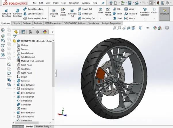
Features used to Create
- Sketch
- Sketch fillet
- Extruded boss
- Extruded cut
- Revolved cut
- Circular pattern
- Combine
- Fillet
- Chamfer
Sketch fillet
It round the corner at the intersection of two sketch entities, creating a tangent arc.
Extruded cut
It cuts a solid model by extruding a sketched profile in one or two direction.
Revolved cut
It cuts a solid model by revolving a sketched profile around an axis.
Rear Wheel
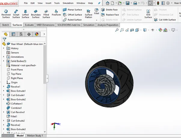
Features used to Create
- Sketch
- Sketch fillet
- Extruded boss
- Extruded cut
- Revolved cut
- Circular pattern
- Combine
- Chamfer
Front Fork
It is a hydraulic shock absorbers with internal coil spring.it absorb the impact and then rebound it back.
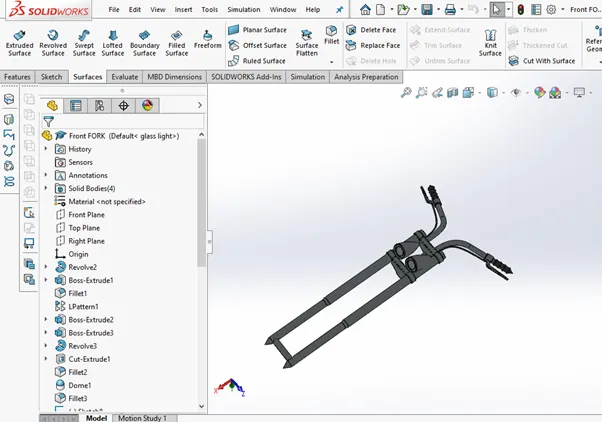
Features used to Create
- Sketch
- Extruded boss
- Extruded cut
- Revolved cut
- Liner pattern
- Fillet
- Dome
- Move/copy body
- Sweep
- Mirror
- Projected curve
- Combine
Move/copy body
It used to move or copy the body from one place to another place.
Sweep
It create a solid feature along an open or closed path and gives a 3D
View.
Mirror
It mirror pre-existing 2D sketch about a face or a plane. Here in the fork one part is created and other part is mirrored. Then we combine both the part as a whole body.
Projected curve
It is curve created by selecting two different 2D sketches to give a 3D kind of curve.
Chassis
It is the supporting frame of a structure. It is the load bearing framework of an artificial object. Here in this we are going to mount all the individual part of chopper.
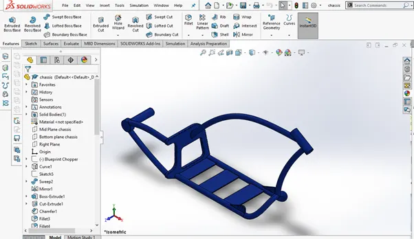
Features used to Create
- Sketch
- Sketch picture
- Projected curve
- Sweep
- Mirror
- Boss extrude
- Cut extrude
- Chamfer
- Fillet
- Dome
- Split
- Combine
- Revolve boss
Sketch picture
It is used for the reference only by placing it in background as a blueprint. To bring it onto your sketch plane go to Tool bar and under sketch tools you select the sketch picture.
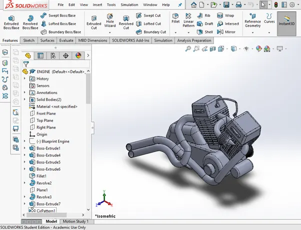
Engine
It is a machine for converting any of various forms of energy into mechanical force and motion. The engine is the heart of your chopper.
Features used to Create
- Sketch
- Sketch picture
- Projected curve
- Sweep
- Mirror
- Boss extrude
- Cut extrude
- Chamfer
- Fillet
- Dome
- Circular pattern
- Composite curve
- Revolve boss
- Split
Composite curve
It is used to make a single curve by joining two curves.
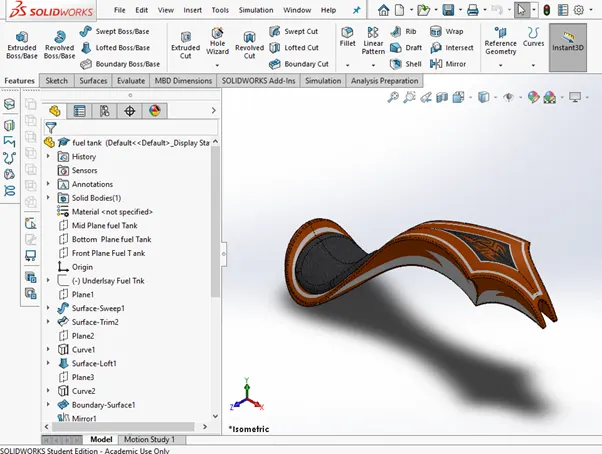
Gas tank
It is used to store the required amount of gas and give it to the engine when it required.
Features used to Create
- Sketch
- Sketch picture
- Projected curve
- Surface sweep
- Surface Trim
- Surface loft
- Boundary surface
- Surface knit
- Split
- Surface extrude
- Cut sweep
- Fillet
- Shell
Surface sweep
It creates a surface feature by sweeping an open or closed profile along the selected path.
Surface Trim
It trim a surface where one surface intersect with another surface or a plane.
Surface loft
It created a lofted surface between two or more profiles.
Boundary surface
It lets you create surfaces that can be tangent or continuous in both direction.
Surface knit
It combines two or more surfaces together.
Surface extrude
Like extrude boss it creates a solid surface and gives a 3D view.
Cut sweep
It cuts a solid model by removing material with a surface.
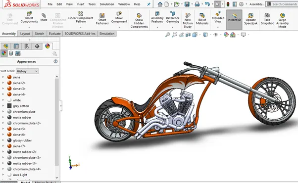
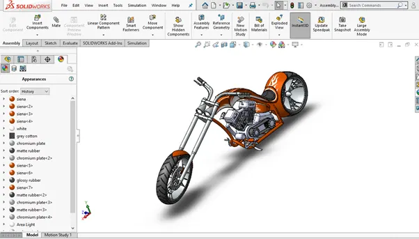
Assembly of chopper
For assembly we have to select the assembly option in solidwork home page. First insert the chassis by selecting insert part option and fix it and then insert all the individual part by giving proper relation and all possible mates.
Features used to Create
- Insert component
- Mate
Insert component
It adds the all existing part into assembly.
Mate
It positions two components relative to one another and creates geometric relationships between assembly components.
Solidwork visualization
It allows you to create photo-quality content in the fastest and easiest way. you can form images to animations, interactive web content, and immersive Virtual Reality. Bring your products to life.
Render
Rendering is the process of generating a photorealistic or non-photorealistic image from a 2D or 3D model by means of a computer program.
Photo View 360
It Provides a highly interactive environment for viewing designs as well as for creating photo-realistic renderings that can be used to showcase your designs.

Conclusion
Here we modeled an American chopper by using solidwork cad software and appropriate tools and we give it a realistic effect by solidwork visualization.