Advanced Sheet Metal Design Using NX Cad Challenge_2_Box Assembly
OBJECTIVE
The main objective to design this is to familiar with different tools in NX CAD
software and what the process we are going to follow to get our output.
Introduction
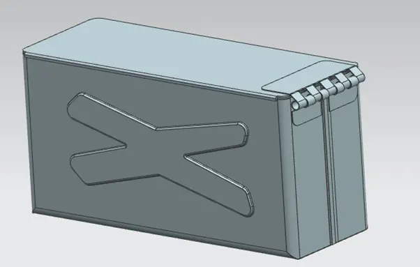
Here we are going to Create different parts of a box using NC CAD software by using different tools and finally we give it a proper view.
DESIGN METHODOLGY
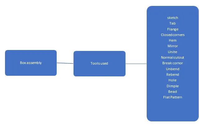
Tools
sketch
It is the basis of a 3D model. You can create on any plane.
Tab
It create a base feature by extruding a sketch along a vector by a thickness value or adds material to a planer face.
Flange
It adds a flat flange at an angle to a planer face and adds a bend between the two.
Closed corners
It closes a corner where two adjacent flanges meet by extending the bends and flanges.
HEM Flange
It modifies the model by folding the edge of sheet metal flange over onto itself for purpose of safe handling or to increase edge stiffness.
Mirror
It copies a feature or a body and mirror it across a plane.
Unite
It combines the volume of two or more solid bodies into one single body.
Normal cut out
It cuts material by projecting a sketch onto the model and then cutting perpendicular to the faces intersected by the projection.
Break corner
It rounds or chamfer the sharp corner of a tab or flange.
Unbend
It flattens a bend and the material adjacent to the bend.
Re bend
It restores the an unbend feature to its original bent state.
Hole
It adds a hole one or more in a solid body.
Dimple
It lifts an area of the model inside a sketch that simulates a stamping tool.
Bead
It lifts the material along the counter of a sketch that simulates a stamping tool.
Flat Pattern
It creates flat pattern from the formed sheet metal part.
Procedure
- Open NXCAD create a new model .
- Crate a sketch in a XY plane , draw a rectangle centered at origin give the dimensions and exit the sketch.
- Create a solid sheet by using “Tab” tool and give thickness.
- Add two flanges to the two opposite side of tab and give length.
- Add two more flanges at 90 degree angle to the two created flanges.
- Now close the two corners of two created flanges by using closed corners icon.
- Now create two more flanges by adding the two create flanges having bend radius 0 and length 0.02 and create another two more flanges adding to that two flanges and give length of 6.5.
- Now add open Hem to the edges of two created flange by using Hem flange icon.
- Now mirror the body across it and unite them as a single body by using unite feature.
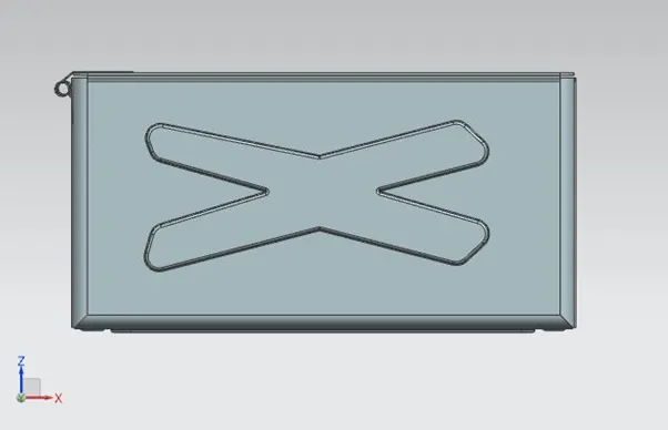
- Now create a cross type dimple to the one side of flange and mirror it to the opposite side.
- Now create a rectangle type dimple on the base Tab and unbend and re bend it.
- Now create a bead to the one corner of tab and mirror it to the other three corners of tab.
- Now add hem flange to the all edges of created flange for safety handling purpose.
- Create a datum plane by giving offset to the reference XY plane and create a sketch a on that plane.
- Draw lid of the feature and create a Tab by using Tab feature add flange to the one end of tab.
- Crate a rectangular tab on one side of flange and cut the sharp edges by using break corner icons.
- Now create a flange to the edge of created tab and create another flange to that flange with angle of 40 degree.
- Now create a hem to that flange with sweep angle 325 degree.
- Now unbend it and create a rectangular cutout and re bend it and mirror it to the side flange.
- Now create a tab on the top of lid tab and cut the sharp edge corners using break corner option and create a flange to the side of tab with angle of 40 degree and adjust the parameter.
- Now unbend it and do normal cutout by matching the feature.
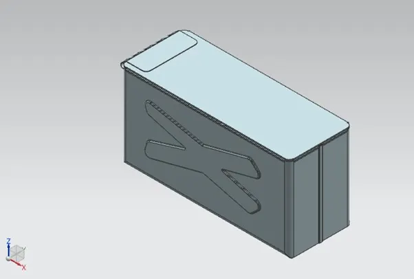
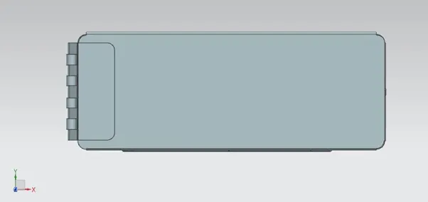
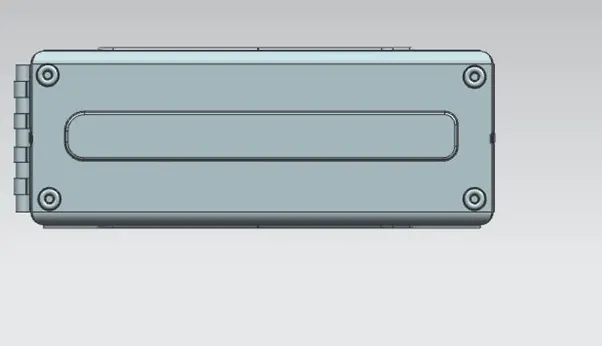
conclusion
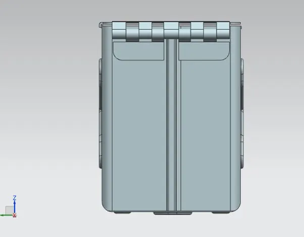
Finally we created our box assembly using NC CAD software by using different tools .