REVIT_Creation of Basic Drawing_Week-2
1)What is BIM? Summarize the features of BIM and benefits of using BIM over 2D CAD tools.
- Building Information Modelling(BIM) is a process for creating and managing information on a construction project across the project lifecycle
- It is concept created by Autodesk
- BIM software products are frequently used in the architecture and construction industries because these industries are entirely focused on building large structures.Since these industries make up the vast majority of BIM software users, these solitions tend to offer tool sets specifically for users in these fields.
- BIM software is not for architects.These tools are applicable or used in different fields like AEC(Architecture,Engneering,Construction),MEP (Mechanical,Electrical,Plumbing)and structural engineering
FEATURES OF BIM:
The following features can typically be found in any BIM software is:
- Easy access to information
- Import/Export 2D designs
- 3D MODELLING
- 3D Rendering
- Sequencing steps
- Document storage
- Mechanical,electrical, and plumbing(MEP) fabrication detailing
BENEFITS OF USING BIM OVER 2D CAD TOOLS:
There are many benefits of using BIM some of them are
- Minimizes the time to complete the project
- Track project history
- Improve colloboration between teams
- Reducing delays and errors
- one can design the project from any location
- Simulate and Visualize at an early stage of the project
- Improvement of occupational,safety and health.
-
2)) Understand the concept of Categories, Families, Elements, Instances in Revit. Go to Insert Tab, choose a category. Pick a family and element. Understand the instances and insert it to Revit model
AIM:CATEGORIES:
- Categories are the one which properties are already present and those properties are predefined and which cannot be further added or deleted for our requirements.
- Categories are one for identifying the inferred type of an element such as anything in the wall category should considered as a wall
- FOR EX:WALL,FLOOR,DOOR ETC
- Few examples of categories are below
-

FAMILIES:
- Families are one where group of elements that share a common property
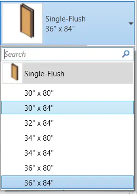
- Revit families has many families like "SINGLE FLUSH"door family,"BASIC WALL"wall family etc
-
ELEMENTS:
- Everthing in Revit is an element.
INSTANCES :
- Parameter enables one to modify the parameter value seperately for every instance.
AIM: TO UNDERSTAND THE INSTANCES AND INSERT IT TO A REVIT MODEL BY PICKING A FAMILY AND ELEMENT
TOOLS AND COMMANDS USED:
-
INSERT
-
LOAD FAMILY INSTANCES
-
ELEMENTS
CATEGORIES
PROCEDURE:
STEP-1: Go to revit
STEP-2:Now select the view bar and choose load family
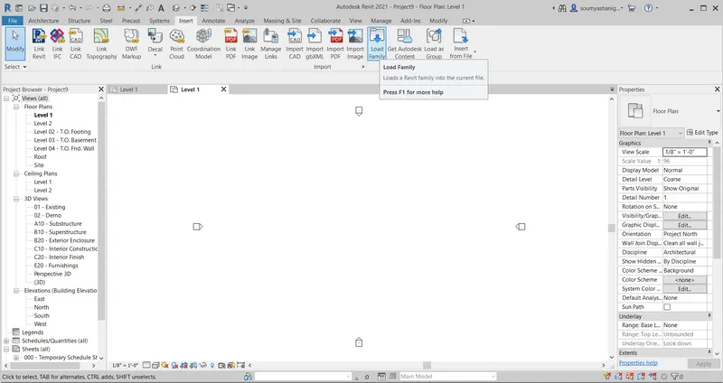
STEP-3:after clicking load family a dialog box appears.
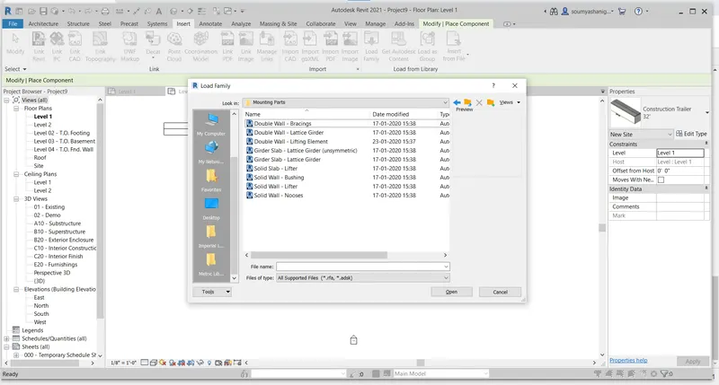
STEP-4: Select the required element or family and click on open.
RESULT:Concept of categories,families,and elements are understood
3) Setting up a Project – Open a project file with architectural template. Save the file with appropriate name. Set up the project units to Imperial / Metric based on your convenience of modelling. Complete the project information under Manage tab. Set up the maximum backups for project file to 3
AIM:TO SET UP A PROJECT AND SAVE THE PROJECT DETAILS AND TO SET MAXIMUM BACKUPS FOR PROJECT FILE TO 3.
TOOLS/COMMANDS USED:
- OPEN
- SAVE
- MANAGE TAB
- PROJECT INFORMATION
- FILE
PROCEDURE:
STEP-1:Open Revit
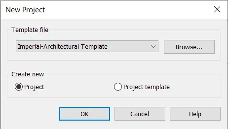
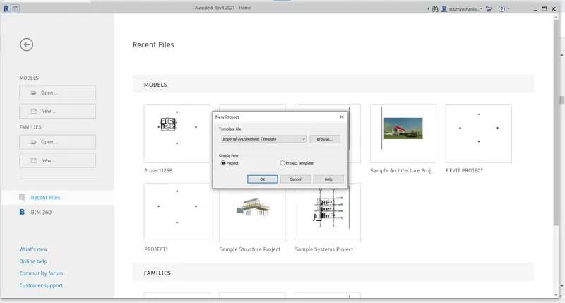
STEP-2:Open the file and choose new and select project
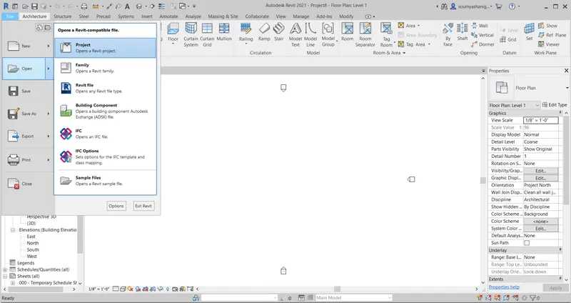
STEP-3:Chose imperial architectural template and click ok
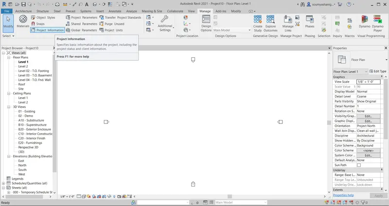
STEP-5:Open manage tab and select project information
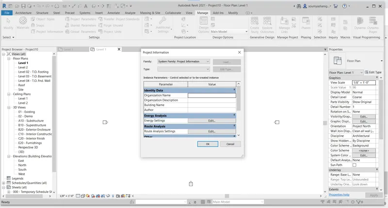
Step-6:After clicking a daialog appears and fill the required details in dialog box
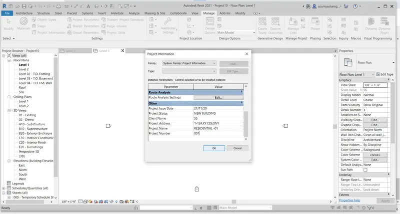
STEP-7:After filling details click ok
STEP-8:Now click on File tab again and click on save as and select project
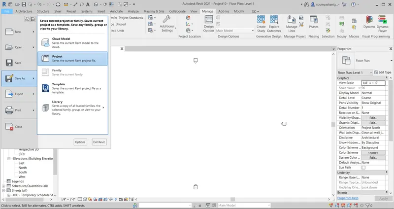
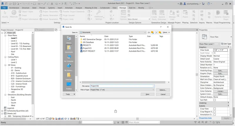
step-8: A dialog box appears ,then fill the details required that is given to project
STEP-9:Select options then a dialog appears and change the maximum number to 3 and click ok
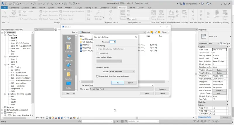
RESULT: A new project is successfully created and saved the project information details and maximum backups are successfully set to 3
4)Understand the concept of Levels and Grids. Follow the naming and conventions. Create the following Levels: ( Convert to metric equivalents if metric is your units)
Ground Floor @ 0’
First Floor @ 10’
Second Floor @ 20’
Roof @ 30’
Grids Transverse Grids A, B,C,D, E @ 10’ spacing
Longitudinal Grids from 1 to 10 @ 20’ spacing
A)AIM:TO CREATE DIFFRENT LEVELS I.E (FIRST FLOOR,SECOND FLOOR,ROOF,GROUND FLOOR) AND NAME THEM
TOOLS/COMMANDS USED:
- View
- Elevation
- Properties broswer
- East
PROCDURE:
STEP-1: Open Revit software and select architectural template and click ok
STEP-2:Select view tab and choose elevation or choose elevation from project browser and select east option
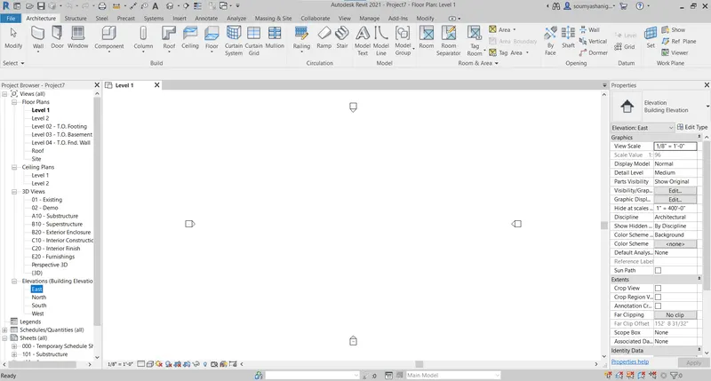
STEP-3:After clicking a different levels appears on the screen
STEP-4:make required changes to the different levels and name them as required.
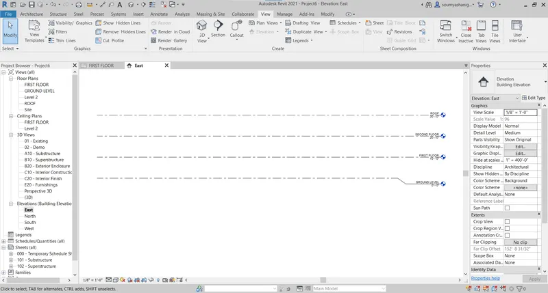
RESULT:The different levels are created and named them as required.
B)AIM:TO DRAW THE GRIDS OF LONGITUDINAL AND TRAVERSE
TOOLS/COMMANDS USED:
- GRID
- ARCHIETECTURAL
- ARCHIETECTURAL TEMPLATE
PROCEDURE:
STEP-1:open the Revit and select Archietectural template then click ok
STEP-2:Select archietectural tool bar
STEP-3: Choose grid option which is at the right most corner

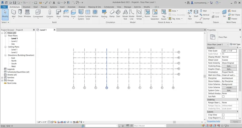
STEP-4:Draw 5 traverse grid lines of offset of 10'and name them as A,B,C,D & E( the naming is should be done from bottom to top or top to bottom in ascending order)
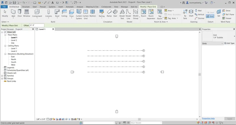
STEP-5:Now draw longitudinal grid lines of offset of 20' and name them as 1-10(the naming is should be done from left to right or right to left but it should be in ascending order)
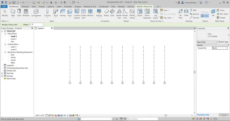
RESULT: The different grids and levels were drawn by using required tabs and named them accordingly
5) 3D modelling of residential unit – From looking at your house / or a place you aspire. Create a conceptual layout of the residential unit. You can measure using a tape or
you can access your residential plan to create a similar layout.
AIM:TO CREATE A LAYOUT OF RESIDENTIAL UNIT AND TO VIEW THE LAYOUT IN 3D VIEW
TOOLS/COMMANDS USED:
- ARCHIETECTURAL
- DOOR
- WALL
- 3D VIEW
- VIEW
PROCEDURE:
STEP-1: Open the revit and select the architecture template and click ok
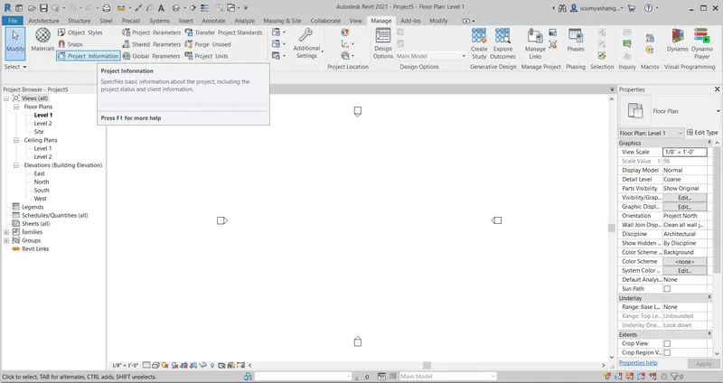
STEP-2:Now go to manage tab and save the project name and details in project information tab and click ok
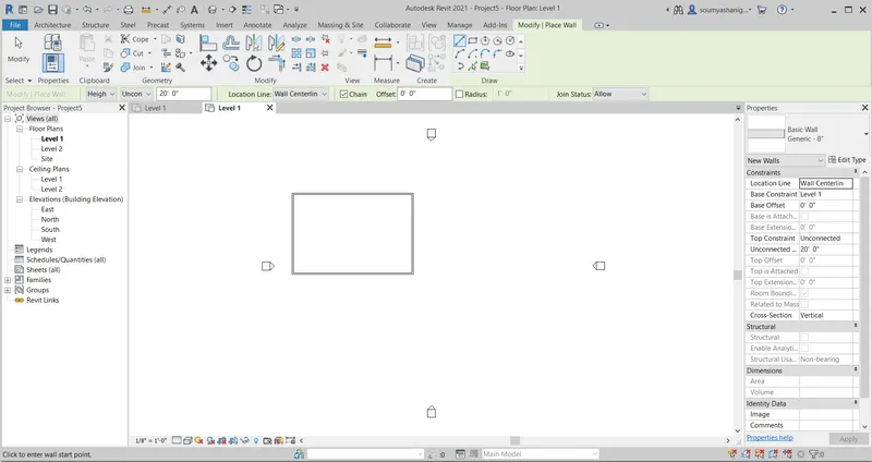
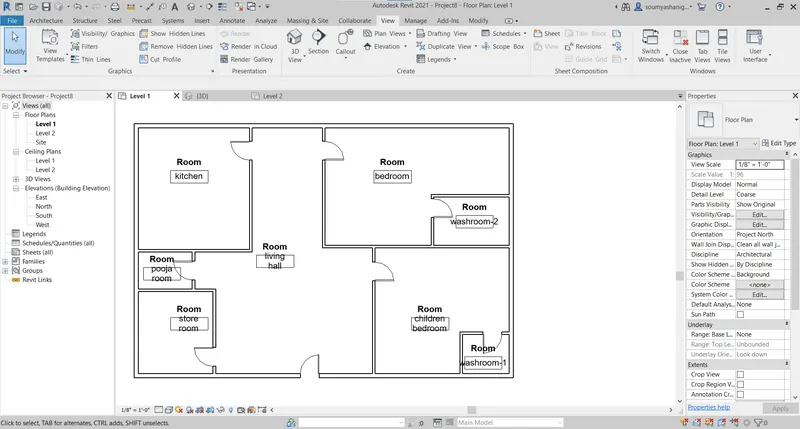
STEP-3:Now click on Architectural bar and select wall and draw a layot of 60'X40'.
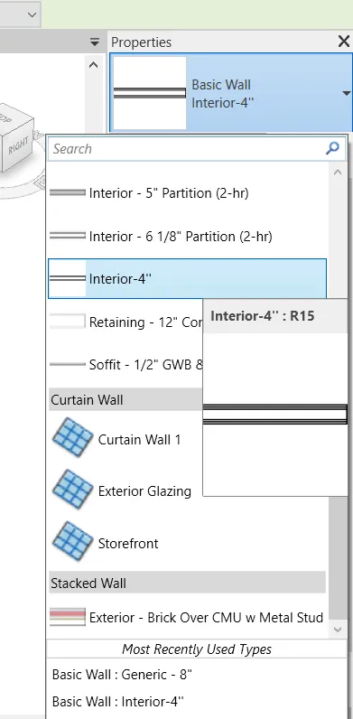
STEP-4:Now draw interior walls by selecting interior wall which is avaialbe in properties and after select interior wall 4'' draw the rooms of reguired length.
STEP-5:Now name the rooms by clicking room tab which is available after clicking architecture tab

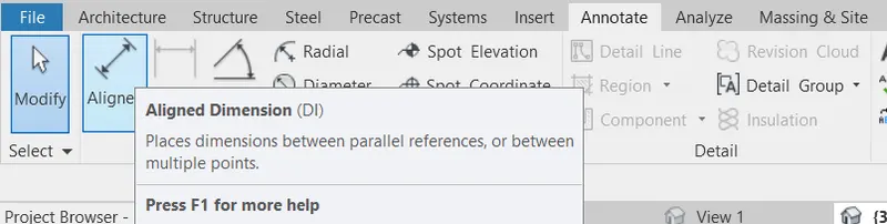
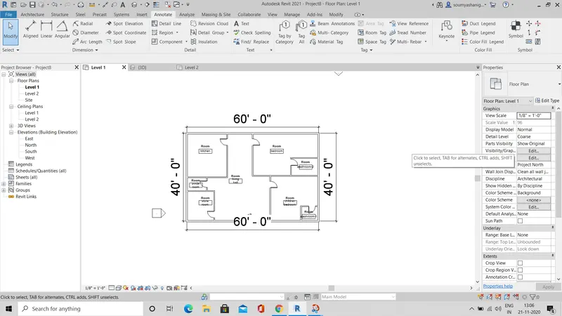
STEP-6:Now mention dimensions to layout by using allign option which is available by clicking annotate tab
now mention dimensions as required.
STEP-7:NOW go to the view tab and select 3D VIEW and click on 3D DEFAULT view

STEP-8: Now the view changed to 3D view
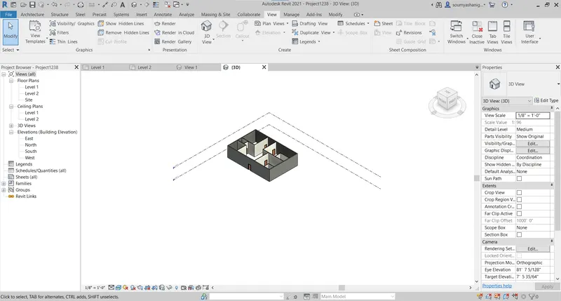
RESULT : A LAYOUT IS CREATED SUCCESSFULLY AND THE LAYOUT IS VIEWED IN 3D VIEW BY VIEW TAB
6) In the layout created draft the level of details you are planning to include – Dimensions of room, components you plan to add in the residential unit.
AIM:TO DRAFT THE LEVELS OF LAYOUT AND TO ADD DIMENSIONS OF ROOM AND COMPONENTS
TOOLS/COMMANDS USED:
- 3D VIEW
- UNCONNECTED
- ANNOTATE
- ALIGN DIMENSIONS
- COMPONENTS
PROCEDURE:
STEP-1:The layout is created in previous example is taken and click on view tab and select 3DVIEW and choose 3Ddefault view

STEP-2: now the view changes to 3D view
STEP-3:To draft the levels of different double click on external wall then one of the wall will be selected then change the dimesions of the wall by using propeties paletee to level all walls
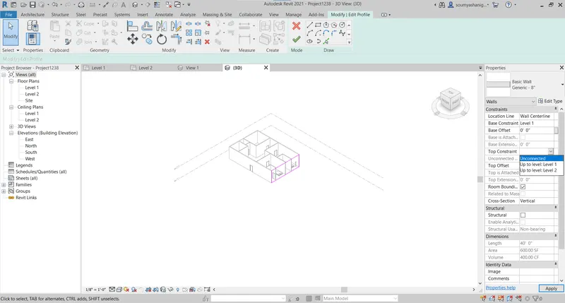
STEP-4: Now click on top constraint arrow then a group of levels appear then slect the require changes like to set all walls or levels in same then select on upto LEVEL-2 then click on apply
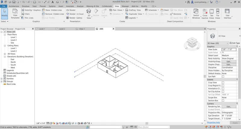
STEP-5: Now view the layout in LEVEL-1 and click on ANNOTATE TAB and select on alligned dimesions to mention the dimensions to the layout
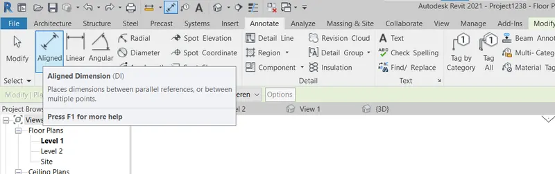
STEP-6:mention the dimensions to the layout
STEP-7:Now measure the different rooms length by using allign tab which is selected from annotate tab
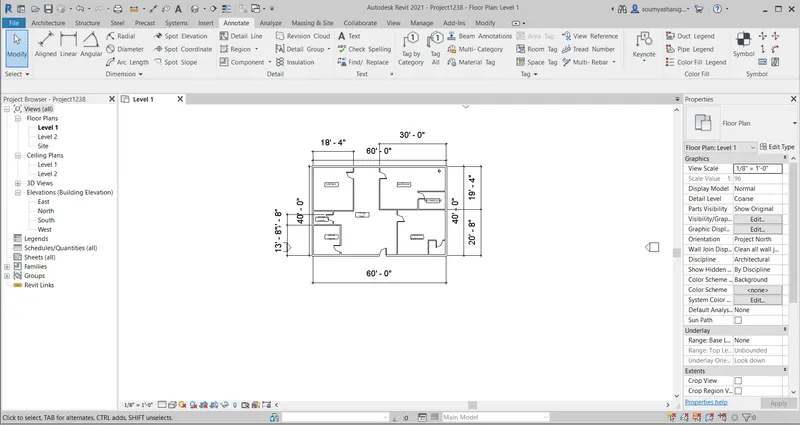
RESULT:THE LAYOUT IS DIMENSIONED AND COMPONENTS OF ROOM ARE ALSO DIMENSIONED BY ALLIGNED TAB AND LAYOUT IS LEVELLED.
7)Identify the residential model elements such as Door, Windows, Tables, Chair, Couch, Bed, Lamps from the library and insert them to the model . Save the project for use
for Assignment 3
AIM: TO IDENTIFY THE MODEL ELEMENTS AND INSERT THEM TO MODEL AND TO SAVE THE PROJECT
TOOLS/COMMANDS USED:
- INSERT
- COMPONENTS
- LOAD FAMILY
- ELMENTS
- SAVE
PROCEDURE:
STEP-1:A layout is created and mentioned the procedure to draw layout in previous example
STEP-2:now go to insert tab and select load families

STEP-3: After clicking load family one can have many options so one can select the required items to place in layout cretaed
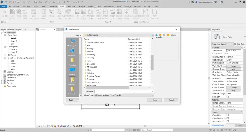
STEP-4:Now select the required element and click on architecture tab and select on elements and chose place element then one can get required components and place them in neccessary place
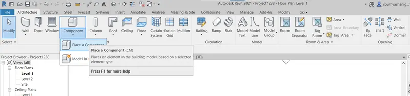
STEP-5: follow the same procedure i.e go to load family and select the require element ans place the element in the layout by place component tab
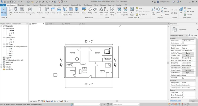
STEP-6:now the view the layout in 3D VIEW
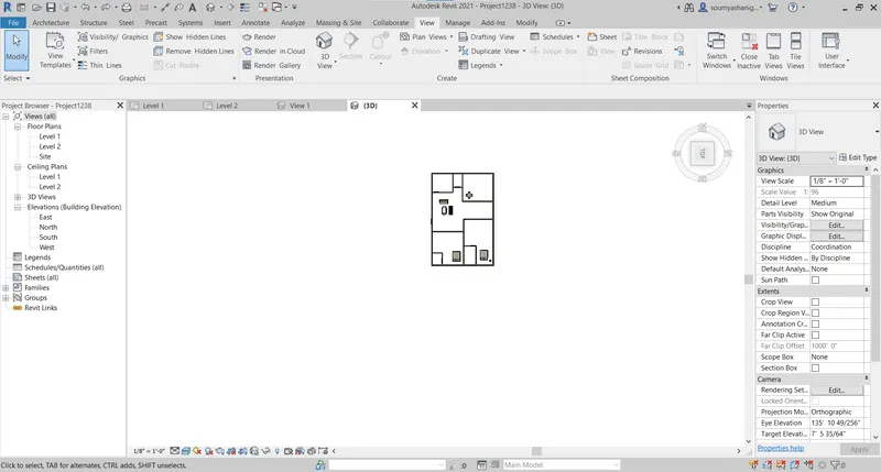
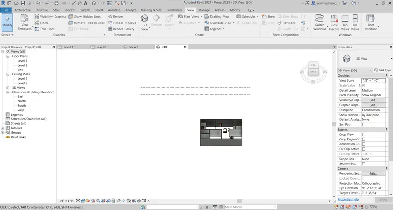
STEP-7 : save the project in save as for futher use.
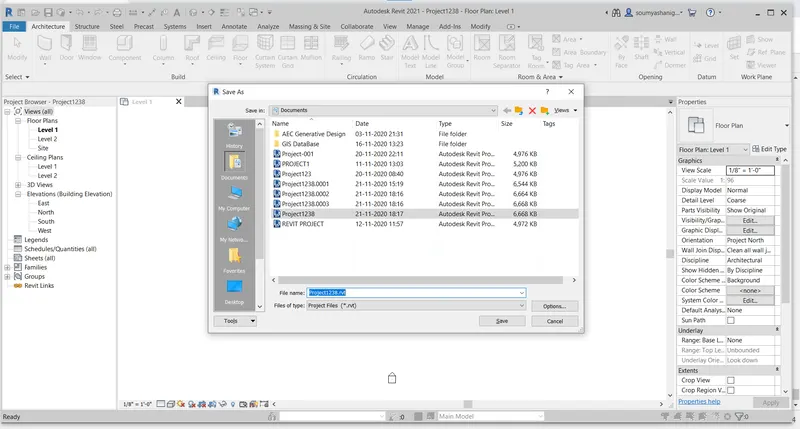
RESULT:the layout is successfully mentioned components like bed,sofa etc were added and saved the project for further use